
huddling chamber safety valve pricelist

EMERSON.BIRKETT WB SERIES SAFETY RELIEF VALVESSpring loaded safety relief valves with a fuff lift and fuff nozzle to relieve excess pressure safefy in a variety of process vesselsFEATURES GENERAL APPLICATION The WB series is designed to refieve excess pressure safefy in pumps, pipe work, tanks, caforifiers, gas and oif separators and other process vessefs. Modefs are avaifabfe for gas, steam, vapor and fiquid appfications. TECHNICAL DATA Materiafs: Carbon steef, stainfess steef DN 2001 Connections Ffanged ANSI 150# to Pressure: Up to 6000 psig (414 barg) • Fuff nozzfe, fuff fift provides high discharge coefficients and high capacities. • Broad sefection of vafve types: conventionaf or beffows for gas or fiquid service enabfes optimum vafve sefection. • Wide range of materiafs provides sofutions for any appfication. • Lightweight construction reduces handfing and shipping costs and benefits offshore service. • Seat feakage integrity minimizes fugitive emissions. • Interchangeabfe parts enabfe simpfe modification from gas to fiquid and conventionaf to beffows. • In-situ testing capabifity reduces maintenance costs. • Reduced number of parts minimizes inventory and reduces maintenance costs. • Vafves conform to API 526 pressure/ temperature ranges, orifice areas and dimensions. • Extensive accessory range enabfes vafves to be adapted to meet specific code and appfication requirements. • Optionaf cfeaning for cryogenic and oxygen services avaifabfe. Emerson.com/FinalControl © 2017 Emerson. Aff Rights Reserved VCTDS-03791-EN 18/01
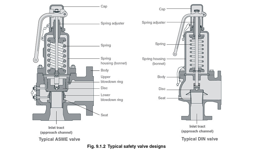
BIRKETT WB SERIES SAFETY RELIEF VALVES OVERVIEW MODEL OPTIONS The WB Series is available in four different valve types to suit differing service requirements: WB400 - conventional gas type. WB300 - bellows gas type. WB200 - conventional liquid type. WB100 - bellows liquid type. CONVENTIONAL SAFETY RELIEF VALVES These valves can be used on systems where the discharge is relatively simple. The pressure in the discharge system can be atmospheric, at a constant level or where it may build up to a maximum of 10% of the set pressure. When a constant back pressure exists, the valve should be set...
BIRKETT WB SERIES SAFETY RELIEF VALVES FEATURES 3. High performance springs 4. Bellows back up piston (not shown) 5. Guiding 6. Bellows (not shown) 7. Trim 8. Seat integrity 9. Adjustable blow down 10. Nozzle design 11. API 526 face to face dimensions Valves can be supplied suitable for application of ‘in-situ’ set pressure verification devices. Wide accessories range to comply with international codes and suit system requirements. High performance springs designed specifically to guarantee set point repeatability. Optional auxiliary back-up piston for balanced bellows valves ensures...
BIRKETT WB SERIES SAFETY RELIEF VALVES OPERATION PRINCIPLE OF OPERATION Spring force Safety relief valves use a spring force to hold a disc against a nozzle. Under normal system operating pressure, the valve will remain closed as the spring force is greater than the inlet system pressure force. The valve opens when the system pressure force becomes greater than the closing force of the spring. The WB Series are designed to have a short simmer, open rapidly to full lift position and then re-seat at a controlled shut off pressure. This is demonstrated in the graph below, which shows the valve...
BIRKETT WB SERIES SAFETY RELIEF VALVES OPERATION LIFT CYCLE Stage 1 - Closed Inlet pressure < set pressure Huddling chamber Inlet pressure is below the set pressure. The valve is closed and there is no flow through the valve. Reaction hood Exit area Blowdown ring Stage 2 - Simmering Inlet pressure is = > set pressure and < popping pressure Inlet pressure increases to set pressure. At this point, the spring force and system pressure force are equal; a further rise in inlet pressure will then begin to lift the disc slightly. A small amount of fluid is released into the huddling chamber (the...
BIRKETT WB SERIES SAFETY RELIEF VALVES OPERATION THE EFFECT OF BACK PRESSURE The configuration of a closed discharge pipework system, typically for toxic or hazardous duty, can generate back pressure. When applied to the valve outlet, this will affect its performance adversely, unless it is addressed. Back pressure can take three forms: 1. Superimposed constant back pressure This exists permanently and a conventional or bellows valve can be used. A conventional valve can be set at the differential pressure so that the spring load is adjusted to take account of the back pressure. 2. Built up...
BIRKETT WB SERIES SAFETY RELIEF VALVES MATERIALS OF CONSTRUCTION WB 400 - CONVENTIONAL GAS TYPE (up to and including class 600) Part Body Casing Cap Nozzle Disc Disc holder Blowdown ring Guide assy Spindle Lower spring plate Adjusting screw Locking nut Setting screw Setting screw rod Stud Nut Spring Body gasket Cap gasket Set screw gasket Ball Upper spring plate Data plate Hammer drive screw Grooved pin Drain plug Circlip Carbon steel SA 216-WCB CARB ST SA 216-WCB CARB ST SA 216-WCB CARB ST 316 ST ST 316 ST ST ASTM A479-316L SA 351-CF8M ST ST CARBON ST/17-4 ST ST ASTM A479-431 ASTM...
BIRKETT WB SERIES SAFETY RELIEF VALVES MATERIALS OF CONSTRUCTION WB 400 - CONVENTIONAL GAS TYPES (class 900 and above) Part Body Casing Cap Nozzle Disc Disc holder Reaction hood Blowdown ring Guide plate Spindle Lower spring cap Adjusting screw Locking nut Setting screw Setting screw rod Tabwasher Pinning screw Body stud Body nut Casing stud Casing nut Spring Spindle head Body gasket Cap gasket Setting screw gasket Ball Upper spring cap Data plate Hammer drive screw Grooved pin Drain plug Carbon steel SA 216-WCB CARB ST SA 216-WCB CARB ST SA 216-WCB CARB ST 316 ST ST 316 ST ST ASTM...

As soon as mankind was able to boil water to create steam, the necessity of the safety device became evident. As long as 2000 years ago, the Chinese were using cauldrons with hinged lids to allow (relatively) safer production of steam. At the beginning of the 14th century, chemists used conical plugs and later, compressed springs to act as safety devices on pressurised vessels.
Early in the 19th century, boiler explosions on ships and locomotives frequently resulted from faulty safety devices, which led to the development of the first safety relief valves.
In 1848, Charles Retchie invented the accumulation chamber, which increases the compression surface within the safety valve allowing it to open rapidly within a narrow overpressure margin.
Today, most steam users are compelled by local health and safety regulations to ensure that their plant and processes incorporate safety devices and precautions, which ensure that dangerous conditions are prevented.
The principle type of device used to prevent overpressure in plant is the safety or safety relief valve. The safety valve operates by releasing a volume of fluid from within the plant when a predetermined maximum pressure is reached, thereby reducing the excess pressure in a safe manner. As the safety valve may be the only remaining device to prevent catastrophic failure under overpressure conditions, it is important that any such device is capable of operating at all times and under all possible conditions.
Safety valves should be installed wherever the maximum allowable working pressure (MAWP) of a system or pressure-containing vessel is likely to be exceeded. In steam systems, safety valves are typically used for boiler overpressure protection and other applications such as downstream of pressure reducing controls. Although their primary role is for safety, safety valves are also used in process operations to prevent product damage due to excess pressure. Pressure excess can be generated in a number of different situations, including:
The terms ‘safety valve’ and ‘safety relief valve’ are generic terms to describe many varieties of pressure relief devices that are designed to prevent excessive internal fluid pressure build-up. A wide range of different valves is available for many different applications and performance criteria.
In most national standards, specific definitions are given for the terms associated with safety and safety relief valves. There are several notable differences between the terminology used in the USA and Europe. One of the most important differences is that a valve referred to as a ‘safety valve’ in Europe is referred to as a ‘safety relief valve’ or ‘pressure relief valve’ in the USA. In addition, the term ‘safety valve’ in the USA generally refers specifically to the full-lift type of safety valve used in Europe.
Pressure relief valve- A spring-loaded pressure relief valve which is designed to open to relieve excess pressure and to reclose and prevent the further flow of fluid after normal conditions have been restored. It is characterised by a rapid-opening ‘pop’ action or by opening in a manner generally proportional to the increase in pressure over the opening pressure. It may be used for either compressible or incompressible fluids, depending on design, adjustment, or application.
Safety valves are primarily used with compressible gases and in particular for steam and air services. However, they can also be used for process type applications where they may be needed to protect the plant or to prevent spoilage of the product being processed.
Relief valve - A pressure relief device actuated by inlet static pressure having a gradual lift generally proportional to the increase in pressure over opening pressure.
Relief valves are commonly used in liquid systems, especially for lower capacities and thermal expansion duty. They can also be used on pumped systems as pressure overspill devices.
Safety relief valve - A pressure relief valve characterised by rapid opening or pop action, or by opening in proportion to the increase in pressure over the opening pressure, depending on the application, and which may be used either for liquid or compressible fluid.
In general, the safety relief valve will perform as a safety valve when used in a compressible gas system, but it will open in proportion to the overpressure when used in liquid systems, as would a relief valve.
Safety valve- A valve which automatically, without the assistance of any energy other than that of the fluid concerned, discharges a quantity of the fluid so as to prevent a predetermined safe pressure being exceeded, and which is designed to re-close and prevent further flow of fluid after normal pressure conditions of service have been restored.

Many electronic, pneumatic and hydraulic systems exist today to control fluid system variables, such as pressure, temperature and flow. Each of these systems requires a power source of some type, such as electricity or compressed air in order to operate. A pressure Relief Valve must be capable of operating at all times, especially during a period of power failure when system controls are nonfunctional. The sole source of power for the pressure Relief Valve, therefore, is the process fluid.
Once a condition occurs that causes the pressure in a system or vessel to increase to a dangerous level, the pressure Relief Valve may be the only device remaining to prevent a catastrophic failure. Since reliability is directly related to the complexity of the device, it is important that the design of the pressure Relief Valve be as simple as possible.
The pressure Relief Valve must open at a predetermined set pressure, flow a rated capacity at a specified overpressure, and close when the system pressure has returned to a safe level. Pressure Relief Valves must be designed with materials compatible with many process fluids from simple air and water to the most corrosive media. They must also be designed to operate in a consistently smooth and stable manner on a variety of fluids and fluid phases.
The basic spring loaded pressure Relief Valve has been developed to meet the need for a simple, reliable, system actuated device to provide overpressure protection.
The Valve consists of a Valve inlet or nozzle mounted on the pressurized system, a disc held against the nozzle to prevent flow under normal system operating conditions, a spring to hold the disc closed, and a body/Bonnet to contain the operating elements. The spring load is adjustable to vary the pressure at which the Valve will open.
When a pressure Relief Valve begins to lift, the spring force increases. Thus system pressure must increase if lift is to continue. For this reason pressure Relief Valves are allowed an overpressure allowance to reach full lift. This allowable overpressure is generally 10% for Valves on unfired systems. This margin is relatively small and some means must be provided to assist in the lift effort.
Most pressure Relief Valves, therefore, have a secondary control chamber or huddling chamber to enhance lift. As the disc begins to lift, fluid enters the control chamber exposing a larger area of the disc to system pressure.
This causes an incremental change in force which overcompensates for the increase in spring force and causes the Valve to open at a rapid rate. At the same time, the direction of the fluid flow is reversed and the momentum effect resulting from the change in flow direction further enhances lift. These effects combine to allow the Valve to achieve maximum lift and maximum flow within the allowable overpressure limits. Because of the larger disc area exposed to system pressure after the Valve achieves lift, the Valve will not close until system pressure has been reduced to some level below the set pressure. The design of the control chamber determines where the closing point will occur.
A safety Valve is a pressure Relief Valve actuated by inlet static pressure and characterized by rapid opening or pop action. (It is normally used for steam and air services.)
A low-lift safety Valve is a safety Valve in which the disc lifts automatically such that the actual discharge area is determined by the position of the disc.
A full-lift safety Valve is a safety Valve in which the disc lifts automatically such that the actual discharge area is not determined by the position of the disc.
A Relief Valve is a pressure relief device actuated by inlet static pressure having a gradual lift generally proportional to the increase in pressure over opening pressure. It may be provided with an enclosed spring housing suitable for closed discharge system application and is primarily used for liquid service.
A safety Relief Valve is a pressure Relief Valve characterized by rapid opening or pop action, or by opening in proportion to the increase in pressure over the opening pressure, depending on the application and may be used either for liquid or compressible fluid.
A conventional safety Relief Valve is a pressure Relief Valve which has its spring housing vented to the discharge side of the Valve. The operational characteristics (opening pressure, closing pressure, and relieving capacity) are directly affected by changes of the back pressure on the Valve.
A balanced safety Relief Valve is a pressure Relief Valve which incorporates means of minimizing the effect of back pressure on the operational characteristics (opening pressure, closing pressure, and relieving capacity).
A pilotoperated pressure Relief Valve is a pressure Relief Valve in which the major relieving device is combined with and is controlled by a self-actuated auxiliary pressure Relief Valve.
A poweractuated pressure Relief Valve is a pressure Relief Valve in which the major relieving device is combined with and controlled by a device requiring an external source of energy.
A temperature-actuated pressure Relief Valve is a pressure Relief Valve which may be actuated by external or internal temperature or by pressure on the inlet side.
A vacuum Relief Valve is a pressure relief device designed to admit fluid to prevent an excessive internal vacuum; it is designed to reclose and prevent further flow of fluid after normal conditions have been restored.
Many Codes and Standards are published throughout the world which address the design and application of pressure Relief Valves. The most widely used and recognized of these is the ASME Boiler and Pressure Vessel Code, commonly called the ASME Code.
is the calculated mass flow from an orifice having a cross sectional area equal to the flow area of the safety Valve without regard to flow losses of the Valve.
the pressure at which a Valve is set on a test rig using a test fluid at ambient temperature. This test pressure includes corrections for service conditions e.g. backpressure or high temperatures.
is the value of increasing static inlet pressure of a pressure Relief Valve at which there is a measurable lift, or at which the discharge becomes continuous as determined by seeing, feeling or hearing.
Because cleanliness is essential to the satisfactory operation and tightness of a safety Valve, precautions should be taken during storage to keep out all foreign materials. Inlet and outlet protectors should remain in place until the Valve is ready to be installed in the system. Take care to keep the Valve inlet absolutely clean. It is recommended that the Valve be stored indoors in the original shipping container away from dirt and other forms of contamination.
Safety Valves must be handled carefully and never subjected to shocks. Rough handling may alter the pressure setting, deform Valve parts and adversely affect seat tightness and Valve performance.
When it is necessary to use a hoist, the chain or sling should be placed around the Valve body and Bonnet in a manner that will insure that the Valve is in a vertical position to facilitate installation.
Many Valves are damaged when first placed in service because of failure to clean the connection properly when installed. Before installation, flange faces or threaded connections on both the Valve inlet and the vessel and/or line on which the Valve is mounted must be thoroughly cleaned of all dirt and foreign material.
Because foreign materials that pass into and through safety Valves can damage the Valve, the systems on which the Valves are tested and finally installed must also be inspected and cleaned. New systems in particular are prone to contain foreign objects that inadvertently get trapped during construction and will destroy the seating surface when the Valve opens. The system should be thoroughly cleaned before the safety Valve is installed.
The gaskets used must be dimensionally correct for the specific flanges. The inside diameters must fully clear the safety Valve inlet and outlet openings so that the gasket does not restrict flow.
For flanged Valves, draw down all connection studs or bolts evenly to avoid possible distortion of the Valve body. For threaded Valves, do not apply a wrench to the Valve body. Use the hex flats provided on the inlet bushing.
Safety Valves are intended to open and close within a narrow pressure range. Valve installations require accurate design both as to inlet and discharge piping. Refer to International, National and Industry Standards for guidelines.
The Valve should be mounted vertically in an upright position either directly on a nozzle from the pressure vessel or on a short connection fitting that provides a direct, unobstructed flow between the vessel and the Valve. Installing a safety Valve in other than this recommended position will adversely affect its operation.
Discharge piping should be simple and direct. A "broken" connection near the Valve outlet is preferred wherever possible. All discharge piping should be run as direct as is practicable to the point of final release for disposal. The Valve must discharge to a safe disposal area. Discharge piping must be drained properly to prevent the accumulation of liquids on the downstream side of the safety Valve.
The weight of the discharge piping should be carried by a separate support and be properly braced to withstand reactive thrust forces when the Valve relieves. The Valve should also be supported to withstand any swaying or system vibrations.
If the Valve is discharging into a pressurized system be sure the Valve is a "balanced" design. Pressure on the discharge of an "unbalanced" design will adversely affect the Valve performance and set pressure.
The Bonnets of balanced bellows safety Valves must always be vented to ensure proper functioning of the Valve and to provide a telltale in the event of a bellows failure. Do not plug these open vents. When the fluid is flammable, toxic or corrosive, the Bonnet vent should be piped to a safe location.
It is important to remember that a pressure Relief Valve is a safety device employed to protect pressure vessels or systems from catastrophic failure. With this in mind, the application of pressure Relief Valves should be assigned only to fully trained personnel and be in strict compliance with rules provided by the governing codes and standards.

Relief and safety Valves are used in high pressure systems to control the pressure and keep balance of the system. The different between safety valves and relief valves is that the safety valves fully open or close under a certain pressure while the relief valves can open in proportion to the pressure in front of them. The safety and pressure relief valves are used automatically. They both operate under similar conditions. When the pressure builds up in a system, it has to be managed by releasing the material to flow through. These valves have a threshold pressure at which they open. The consolidated safety and safety relief valves comprise of a bonnet vent and bellow with springs.
The springs are set up for the threshold pressure and when the pressure exceeds the threshold, the spring is pushed into the bonnet vent and the bellow opens the valve. The Safety Relief Valves can be open and shut valves. They either open or shut off at any given pressure. This is mostly for the safety of an application not to explode under high pressure. The Pressure Relief Valve on the other hand releases the material after the threshold pressure, but not fully. If the pressure is slightly higher the threshold, then the valve opens slightly. If the pressure is very high above the threshold, it opens wider. It also functions in the same manner when the pressure drops down. The valve closes in proportion to the pressure. The safety valve shuts down at once only when the pressure is below the threshold.
Ready Stock of ASTM A351 CF8M Spring Loaded Safety Valve in wide range of Sizes, Stainless Steel Air Compressor Pressure Relief Valve Manufacturers In India
Relief Valves are designed to control pressure in a system While Safety Valves are used for controlling the pressure in a system they release pressure immediately in the event of an emergency or system failure
The Setpoint of relief valve is usually set at 10 Percent above working pressure limit while safety valve is usually set at 3% above working pressure limit.
If you are operating systems that can only be off for short periods of time, it is sensible to keep a spare valve to swap over and then the removed valve can be inspected and recertified.

Boiler contractors see these valves all the time when working on equipment. Generally the steam relief valve is often little understood, often incorrectly installed, and usually neglected. A little refresher on these valves might be in order.
As the pressure of the steam within a boiler approaches the set pressure of the valve, the steam pressure on the underside of the actuating disc approaches the pressure of a spring applied to the outer side of the disc. When equilibrium is passed, the disc starts to lift off its seat. The moment this happens, steam is suddenly released all around the disc to what is called the “huddling chamber.” This chamber increases the area of the disc that sees steam pressure, thus increasing force. This increased area under steam pressure makes the pressure much more unbalanced in the direction of the valve discharge opening and therefore pops the valve into a wide open position. When the valve opens with a “pop” the valve seat is preserved from wiredraw caused by slow opening.
Closure of the valve occurs only after the boiler pressure is dropped several pounds below the set point. The reduction of the area of the disc seeing steam causes the disc to firmly close against the valve seat.
The first area of concern is valve distortion. Valve distortion occurs when the valve is improperly wrenched in, using the valve body instead of supplied wrench flats. Distortion also occurs when the discharge side of the safety relief valve is made to bear the weight of the discharge piping. To prevent this distortion use a short nipple from the valve to an independently supported bell reducer or drip pan elbow. These valves are precision devices and any distortion will affect accuracy and calibration.
The second area of concern is discharge piping. For a safety valve to do its job it must be sized properly to adequately relieve all the steam the boiler is capable of producing while operating at its maximum. All piping to or from a safety relief valve must be at least as large as the valve’s connections. Also, the restrictive effect of elbows and the friction losses in pipe must be taken into account. For this reason, piping runs should be as short as possible and pipe sizes should be generous.
If you need help in replacing or sizing a steam relief valve please contact Stromquist and Company at 1-800-241-9471. All others can order this product from one of our affiliates at CGNA.

Gentzel reissue patent 22,164 for a "Valve Mechanism" was issued August 25,1942, upon reissue application filed July 24, 1940; the original patent,2,145,870, was issued February 7, 1939, upon application filed January 30,
1935. Judge Clancy held all six claims of the reissue patent valid and infringedby defendant"s competing safety valves. The reissue patent concerns frame rodsarranged to support the cross bar of a safety valve for steam boilers. The crossbar, in turn, anchors the upper end of a spring which, due to its state ofcompression between the valve and the cross bar, holds the valve shut until thedesired "pop-off" pressure is achieved. Thus obviously any change due totemperature variations in the configuration of the cross bar and its supportingframe rods will result in a change in the compressive stress exerted on thespring, which, in turn, will cause a change in "pop-off" pressure. Such variationsin "pop-off" pressure are highly undesirable, particularly in high-pressure, hightemperature boilers, since they result either in the maintenance of pressure atdangerously high levels or in waste of useful energy due to "pop-off" atneedlessly low pressures. One of the major reasons for these unwantedvariations stems from the fact that each time the valve pops various partsthereof are bathed in steam and, in the case of some boilers, in superheatedsteam. This overheating of various parts of the valve naturally causes changesin the pressure at which the valve will pop when next subjected to excessivepressure. The object of Gentzel"s patent is to prevent, by frame roads properlyarranged, the increase in heat when the valve first opens from weakening thespring compression, and thereby causing valve to open at lower pressures on itssecond and subsequent openings.3
This, plaintiff Gentzel purports to do (1) by placing the two frame rods whichsupport the cross bar a sufficient distance from the valve so as to minimize theheating effect of the discharged steam on the rods, (2) by securing the bottomof the frame rods to the valve casing at its end nearest the boiler at a sufficientdistance from the initial opening of the valve so as not to be affected by the heatemanating from that point, and (3) by making the frame rods of sufficientlength so that heat will not be conducted through them to the cross bar. Thusplaintiff Gentzel"s claimed invention consists of the positioning, place ofattachment, and length of the frame rods. In essence, his claim to inventivegenius appears to lie in the idea that if one makes frame rods long enough andmoves them far enough away from the source of the hot steam they and partsattached to them will not become undesirably hot.
An examination of the prior art, however, discloses that both the use of framerods in safety valves and their length and positioning as prescribed by plaintiff"spatent had been fully anticipated and disclosed by prior patents. So the Painepatent 102,147, issued in 1870, covers a safety valve employing frame rodssimilar to plaintiff"s. It does not, however, have a valve casing; and the framerods are affixed directly to the steam dome of the boiler, rather than to a casing.The fact that plaintiff, who employs rods of similar length and placement, does
so in connection with a valve having a casing, rather than one without, does notrender plaintiff"s work patentable. It is mere routine mechanical development touse rods having a previously patented configuration in connection with a valvecasing, which plaintiff does not claim to have invented, even though the use ofthe casing will reduce the quantity of steam which may potentially impingeupon the frame rods.5
The Jackson British patent 3172 (1899) discloses a valve casing and frame rodssecured at the lower end of the casing. Plaintiff seeks to distinguish this patenton the ground that the frame rods contain "shoulders" which "bear tightly againstthe top of the casing," thereby causing the rods to be affected by the elongationof the casing. Whatever the merits of this distinction, if the length andpositioning of the frame rods in the Paine patent were combined with the valvecasing and rods secured at its lower end as in the Jackson British patent,plaintiff"s patent would be the result.
Gentzel patent 2,278,437, issued April 7, 1942, on an application filed July 31,1939, and of which eleven of its seventeen claims are here in issue, involvescertain mechanisms which control the release of steam after the valve pops off.The steam in emerging from the nozzle of the valve causes a piston to rise. Thepiston is enclosed in a piston guide, along which it slides. Cut into the innerwall of the guide is a ring-shaped groove, described as an "annular recess" or"exhaust belt." Leading from the groove to the atmosphere are a series of fourholes, also known as "ports" or "apertures," two of which are equipped withmetering valves to control the flow of steam. As a further feature, the piston isserrated to prevent binding or "seizing." Judge Clancy has held all the claimshere put in issue to be valid and infringed.
Plaintiffs assert that the two objectives sought to be achieved by their valvemechanism are (1) maximum lift or opening of the valve in the shortestpossible space of time and (2) minimum "blowdown," i.e., differential betweenvalve opening and closing pressures. In other words, the purpose is to have thevalve open as abruptly and fully as possible and then close immediately afterthe boiler has returned to normal pressure. Plaintiffs intimate that both thesedesired ends are to be achieved through the action of the "annular chamber" andapertures. It appears, however, that in reality the quick lift is provided by a"huddling chamber"-- a conventional device to build up pressure, made byextending the valve disk beyond its seat to afford additional area to be actedupon by the steam, and thus designed to take advantage of the jet action of theescaping steam in such a way as to force the valve to maximum opening.1 Theannular recess and apertures perform merely the function of breaking the jetaction and dispersing the steam so as to provide prompt reseating of the valvewithout excessive blowdown. Since Gentzel makes no claim to have inventedthe "huddling chamber," the patentability of his device turns upon the questionwhether or not the prior art has anticipated his annular recess in its function ofbreaking down jet action and dispersing the steam so as to minimize blowdown.
The Coale patent 459,268 employs a groove and openings to permit the escapeof steam. According to the specification, "the area of these openings can beadjusted with great accuracy to permit the steam to escape from the popchamber at the necessary speed to insure the closing of the valve at the desiredpoint." The groove in the Coale patent is cut in "an annular valve or ring," ratherthan in the valve guide as in the Gentzel patent. It is also true that in the Coalescheme the areas of exhaust holes are controlled by a ring, while Gentzel usesmetering valves to perform the same function. Considering, however, the closesimilarity between the two patents both physically and functionally, these
The Houser patent 1,152,733 does not employ an annular recess or groove; butit does utilize exhaust ports through which steam may escape when the valvepops, thereby minimizing blowdown. Also the area presented for the escape ofsteam is adjustable. The Houser device therefore exemplifies the sameprinciple as Gentzel"s patent. Both patents seek to reduce blowdown byproviding an additional outlet for the escape of steam into the atmospherethrough adjustable areas of outlet. The fact that Gentzel also provides a grooveor "annular recess" is not shown to affect the result achieved.
As for plaintiffs" claim based on the use of a serrated valve piston, this wasanticipated by the Iwanowitsch patent 427,264 and also by the Coale patent459,268. So we find this patent, like the other, to add at most only a slightrefinement by rearrangement or repositioning of old elements to obtain aquicker or more uniform operation of the device. We do not see invention here.Since both patents are invalid so far as in issue before us, we do not reach thedefendant"s further contentions that the claims in the reissue patent 22,164 areunduly vague or that it did not infringe either patent.
We perhaps should note the usual argument for validity because of allegedcommercial success. Beginning in 1939 or perhaps earlier, Foster EngineeringCompany, the sole licensee, has sold about 3,000 Gentzel valves at pricesranging from $300 to $1,000, or a total of $1,500,000, for which Gentzel hasreceived royalty payments of about $90,000. This somewhat modest success fora large operation over a long period does not carry conviction of unique worth.As we have again pointed out, Kleinman v. Kobler, 2 Cir., 230 F.2d 913, wemust not be overnaive in evaluating such claims; and even a greater measure ofsuccess would not establish validity in the face of the clear showing here ofanticipation by the prior art. Jungersen v. Ostby & Barton Co., 335 U.S. 560,567, 69 S.Ct. 269, 93 L.Ed. 235, affirming Jungersen v. Baden, 2 Cir., 166 F.2d807, 811. Of at least equal persuasiveness are the tortuous progress of thesepatents through the Patent Office from 1935 to 1942 and the many emendationsof statement, especially in the second patent, made to meet the objections ofexaminers-- a classic example of what Judge Learned Hand has called "the antlike persistency of solicitors" which overcomes "the patience of examiners, andthere is apparently always but one outcome." See Lyon v. Boh, D.C.S.D.N.Y., 1F.2d 48, 50, reversed on grounds not here apposite, 2 Cir., 10 F.2d 30.
Plaintiffs" witness Stephen G. Farrington testified as follows on redirectexamination:"Q. Is there a huddling chamber in the Gentzel patent 2,278,437? A. Yes, sir."Q. Is there a huddling chamber in the Foster valves that are made inaccordance with the Gentzel patent? A. Yes, sir."Q. Is there a huddling chamber in the defendant"s valve, the Maxiflow valve?A. Yes, sir."Q. In the Gentzel patent and in the Foster valves, in addition to the huddlingchamber there is an exhaust belt associated with the guide, apertures which arein communication with that exhaust belt and the apertures are controlled ormetered."Is the function of a huddling chamber the same or different than the function ofan exhaust belt and metering valves in communication therewith? A. They arenot the same."Q. Why are they different? A. The huddling chamber effect of the nozzle ringcauses a sudden lift, the restriction of the initial flow of steam causing the lift ofthe valve. Once the valve has lifted, there is a considerable increase in thequantity of steam that passes therefrom, reaction and jet action take place on thepiston, and in order to break down this high reaction and jet action caused byvelocity flow under high flow of steam and great quantities, it is necessary totake part of that steam off through this exhaust belt arrangement which isadjustable for various conditions of flow in these valves and for different sizesof valves. They are not synonymous in any way, the two parts, the huddlingchamber and the exhaust belt."Q. Is there a method of breaking down what you call the jet reactive force inthe defendant"s valve? A. Yes, sir."Q. And that"s different from the huddling chamber? A. Different from thehuddling chamber, yes."Q. And what parts of the defendant"s structure perform that function ofbreaking down the jet action in the defendant"s structure looking-- A. Thehorizontal holes O that pass through this part No. 9. * * *"
Think about the physics of what the huddling chamber does, and how it does it. Then it will all make perfect sense. The whole purpose of the huddling chamber is accelerate the opening of the valve....to get the valve into a high left position more quickly. The huddling chamber puts the "pop" into "pop valves". A consequence or trade-off is that it also makes the valve harder to re-close (blowdown).
The huddling chamber accelerates the PSV opening by creating a "secondary orifice". It"s easier to visualize this phenomenon if we talk about a gas (compressible fluid) application. As the gas flows through the primary orifice it then flows through the huddling chamber. At the exit of the huddling chamber the gas is pinched as it passes through the gap created by the blowdown adjustment ring (also referred to as the "nozzle ring"). The pressure on the upstream side of this gap (inside the huddling chamber) is acting on all surfaces, but notice that there"s a lot more surface area on the upper side than the lower side. Thus, this pressure creates additional lifting force, helping the valve get to a higher lift position.
When the gap at the outlet of the huddling chamber is reduced, the blowdown increases. The reduced gap causes a slightly higher pressure in the huddling chamber, thus increasing the lifting force (which necessarily impedes the re-closing of the valve). One can reduce the gap by either lowering the upper piece or raising the lower piece (blowdown adjustment ring).


 8613371530291