
huddling chamber safety valve quotation

The pressure safety valves are used to protect the equipment such as motors, pumps and compressors. The safety valve releases the excess pressure out that can affect the equipment harmfully.
The Pressure Safety Valve that will be produced in the design must refer to the applicable provisions or standards such as ASME, API or other code recommended in the plant or project process. Another thing to note is the construction of the body and material. he “part” design must consider the allowable tension of the material that will be used and must also conform to the standard specifications.
Valve bodies are usually the type of angle (angle type), usually has an outlet that is larger than the inlet. This is very important to “expand” the fluid such as gas, vapour. Safety or relief valves must always do a “relief” to a lower pressure (usually with atmospheric pressure). To achieve this can be done by increasing the size of the pipe outlet in such a way that it can obtain a back pressure of 10% below the inlet pressure price that is permitted to ensure that the valve will open at a predetermined set pressure price. The valve body must have a connection that is able to use its pressure and temperature of use and not only in its operating conditions but also in its relieving conditions.
Body material, for general use (general purpose), is carbon steel. The alloy steel will be used if the pipe specifications require it or for use in certain atmospheric conditions. For the fluid in the form of air, Bronze Alloy is used to pressuring relief devices that are installed in a storage tank (breather valve) usually will be used material made of aluminium material.
The arrangement of the nozzle on the pressure safety valve is divided into two types, namely full-nozzle and semi-nozzle. The full nozzle between the valve body and the nozzle becomes one so that before discharging all parts of the nozzle and disc are wetted by the fluid. Thus if a special material is needed for the nozzle and disc, it must be followed by the part of the valve body
Material spring specification influenced by fluid temperature of standard spring material for pressure safety valve is usually carbon steel or alloy steel (tungsten). For temperature between -240°C to 232°C. carbon steel material is used, for temperatures above 2320C tungsten alloy is used whereas for temperatures below -240C (cryogenic) stainless steel is used on closed bonnet.
When the pressure safety valve has reached the set pressure, it will tend to leak, this is due to the mechanical force balance coming from the bottom of the “disc-area” has reached or the same as the “operated spring” style that is on the top of the disc, leakage on this set pressure can be overcome by:
Blowdown rings are made with the aim to solve two problems, namely: (1) together with the disc-holder to form a “huddling-chamber” which will prepare “pop-action” in the safety valve (2) by adjusting the blowdown ring will change the pressure difference between set pressure and reseating pressure from the valve.

Many electronic, pneumatic and hydraulic systems exist today to control fluid system variables, such as pressure, temperature and flow. Each of these systems requires a power source of some type, such as electricity or compressed air in order to operate. A pressure Relief Valve must be capable of operating at all times, especially during a period of power failure when system controls are nonfunctional. The sole source of power for the pressure Relief Valve, therefore, is the process fluid.
Once a condition occurs that causes the pressure in a system or vessel to increase to a dangerous level, the pressure Relief Valve may be the only device remaining to prevent a catastrophic failure. Since reliability is directly related to the complexity of the device, it is important that the design of the pressure Relief Valve be as simple as possible.
The pressure Relief Valve must open at a predetermined set pressure, flow a rated capacity at a specified overpressure, and close when the system pressure has returned to a safe level. Pressure Relief Valves must be designed with materials compatible with many process fluids from simple air and water to the most corrosive media. They must also be designed to operate in a consistently smooth and stable manner on a variety of fluids and fluid phases.
The basic spring loaded pressure Relief Valve has been developed to meet the need for a simple, reliable, system actuated device to provide overpressure protection.
The Valve consists of a Valve inlet or nozzle mounted on the pressurized system, a disc held against the nozzle to prevent flow under normal system operating conditions, a spring to hold the disc closed, and a body/Bonnet to contain the operating elements. The spring load is adjustable to vary the pressure at which the Valve will open.
When a pressure Relief Valve begins to lift, the spring force increases. Thus system pressure must increase if lift is to continue. For this reason pressure Relief Valves are allowed an overpressure allowance to reach full lift. This allowable overpressure is generally 10% for Valves on unfired systems. This margin is relatively small and some means must be provided to assist in the lift effort.
Most pressure Relief Valves, therefore, have a secondary control chamber or huddling chamber to enhance lift. As the disc begins to lift, fluid enters the control chamber exposing a larger area of the disc to system pressure.
This causes an incremental change in force which overcompensates for the increase in spring force and causes the Valve to open at a rapid rate. At the same time, the direction of the fluid flow is reversed and the momentum effect resulting from the change in flow direction further enhances lift. These effects combine to allow the Valve to achieve maximum lift and maximum flow within the allowable overpressure limits. Because of the larger disc area exposed to system pressure after the Valve achieves lift, the Valve will not close until system pressure has been reduced to some level below the set pressure. The design of the control chamber determines where the closing point will occur.
A safety Valve is a pressure Relief Valve actuated by inlet static pressure and characterized by rapid opening or pop action. (It is normally used for steam and air services.)
A low-lift safety Valve is a safety Valve in which the disc lifts automatically such that the actual discharge area is determined by the position of the disc.
A full-lift safety Valve is a safety Valve in which the disc lifts automatically such that the actual discharge area is not determined by the position of the disc.
A Relief Valve is a pressure relief device actuated by inlet static pressure having a gradual lift generally proportional to the increase in pressure over opening pressure. It may be provided with an enclosed spring housing suitable for closed discharge system application and is primarily used for liquid service.
A safety Relief Valve is a pressure Relief Valve characterized by rapid opening or pop action, or by opening in proportion to the increase in pressure over the opening pressure, depending on the application and may be used either for liquid or compressible fluid.
A conventional safety Relief Valve is a pressure Relief Valve which has its spring housing vented to the discharge side of the Valve. The operational characteristics (opening pressure, closing pressure, and relieving capacity) are directly affected by changes of the back pressure on the Valve.
A balanced safety Relief Valve is a pressure Relief Valve which incorporates means of minimizing the effect of back pressure on the operational characteristics (opening pressure, closing pressure, and relieving capacity).
A pilotoperated pressure Relief Valve is a pressure Relief Valve in which the major relieving device is combined with and is controlled by a self-actuated auxiliary pressure Relief Valve.
A poweractuated pressure Relief Valve is a pressure Relief Valve in which the major relieving device is combined with and controlled by a device requiring an external source of energy.
A temperature-actuated pressure Relief Valve is a pressure Relief Valve which may be actuated by external or internal temperature or by pressure on the inlet side.
A vacuum Relief Valve is a pressure relief device designed to admit fluid to prevent an excessive internal vacuum; it is designed to reclose and prevent further flow of fluid after normal conditions have been restored.
Many Codes and Standards are published throughout the world which address the design and application of pressure Relief Valves. The most widely used and recognized of these is the ASME Boiler and Pressure Vessel Code, commonly called the ASME Code.
is the calculated mass flow from an orifice having a cross sectional area equal to the flow area of the safety Valve without regard to flow losses of the Valve.
the pressure at which a Valve is set on a test rig using a test fluid at ambient temperature. This test pressure includes corrections for service conditions e.g. backpressure or high temperatures.
is the value of increasing static inlet pressure of a pressure Relief Valve at which there is a measurable lift, or at which the discharge becomes continuous as determined by seeing, feeling or hearing.
Because cleanliness is essential to the satisfactory operation and tightness of a safety Valve, precautions should be taken during storage to keep out all foreign materials. Inlet and outlet protectors should remain in place until the Valve is ready to be installed in the system. Take care to keep the Valve inlet absolutely clean. It is recommended that the Valve be stored indoors in the original shipping container away from dirt and other forms of contamination.
Safety Valves must be handled carefully and never subjected to shocks. Rough handling may alter the pressure setting, deform Valve parts and adversely affect seat tightness and Valve performance.
When it is necessary to use a hoist, the chain or sling should be placed around the Valve body and Bonnet in a manner that will insure that the Valve is in a vertical position to facilitate installation.
Many Valves are damaged when first placed in service because of failure to clean the connection properly when installed. Before installation, flange faces or threaded connections on both the Valve inlet and the vessel and/or line on which the Valve is mounted must be thoroughly cleaned of all dirt and foreign material.
Because foreign materials that pass into and through safety Valves can damage the Valve, the systems on which the Valves are tested and finally installed must also be inspected and cleaned. New systems in particular are prone to contain foreign objects that inadvertently get trapped during construction and will destroy the seating surface when the Valve opens. The system should be thoroughly cleaned before the safety Valve is installed.
The gaskets used must be dimensionally correct for the specific flanges. The inside diameters must fully clear the safety Valve inlet and outlet openings so that the gasket does not restrict flow.
For flanged Valves, draw down all connection studs or bolts evenly to avoid possible distortion of the Valve body. For threaded Valves, do not apply a wrench to the Valve body. Use the hex flats provided on the inlet bushing.
Safety Valves are intended to open and close within a narrow pressure range. Valve installations require accurate design both as to inlet and discharge piping. Refer to International, National and Industry Standards for guidelines.
The Valve should be mounted vertically in an upright position either directly on a nozzle from the pressure vessel or on a short connection fitting that provides a direct, unobstructed flow between the vessel and the Valve. Installing a safety Valve in other than this recommended position will adversely affect its operation.
Discharge piping should be simple and direct. A "broken" connection near the Valve outlet is preferred wherever possible. All discharge piping should be run as direct as is practicable to the point of final release for disposal. The Valve must discharge to a safe disposal area. Discharge piping must be drained properly to prevent the accumulation of liquids on the downstream side of the safety Valve.
The weight of the discharge piping should be carried by a separate support and be properly braced to withstand reactive thrust forces when the Valve relieves. The Valve should also be supported to withstand any swaying or system vibrations.
If the Valve is discharging into a pressurized system be sure the Valve is a "balanced" design. Pressure on the discharge of an "unbalanced" design will adversely affect the Valve performance and set pressure.
The Bonnets of balanced bellows safety Valves must always be vented to ensure proper functioning of the Valve and to provide a telltale in the event of a bellows failure. Do not plug these open vents. When the fluid is flammable, toxic or corrosive, the Bonnet vent should be piped to a safe location.
It is important to remember that a pressure Relief Valve is a safety device employed to protect pressure vessels or systems from catastrophic failure. With this in mind, the application of pressure Relief Valves should be assigned only to fully trained personnel and be in strict compliance with rules provided by the governing codes and standards.

A pressure relief valve is a safety device that protects a pressurized vessel or system when the pressure isn’t at the right level. This type of valve opens when a pressure level is reached in order to release the pressure, thus preventing damage to the system or other areas. Types of pressure relief valves are typically used in boilers, pressure vessels and other related systems.
It’s crucial that pressure relief valves are designed with materials that are compatible with many different types of process fluids, ranging from air and water, all the way to corrosive media.
A balanced bellows valves or balanced piston design is used when superimposed back pressure is variable. Wermac.org describes the bellows or piston as being “designed with an effective pressure area equal to the seat area of the disc. The Bonnet is vented to ensure that the pressure area of the bellows or piston will always be exposed to atmospheric pressure and to provide a telltale sign should the bellows or piston begin to leak. Variations in back pressure, therefore, will have no effect on set pressure. Back pressure may, however, affect flow.”
Today, CPV is known around the world for the O-SEAL System of high pressure valves and fittings, the Mark VIII system or tube size valves and fittings, FloMaster air operated shutoff valves, and the new G-Series stainless steel shutoff, needle & check valves.
If you’re in need of any types of high pressure valves or fittings, CPV Manufacturing will provide you with high quality, reliable products that you can count on for years to come. Contact us directly for more information or browse CPV valves online.

We VeeKay Process Instrumentsare manufacturer and exporter and our company is backed by an industry experience of 28 years and we offer process Control Instruments, Instrumentation Equipment, Boiler Accessories, Pipe Line Strainer, Pipe line View Glass/ Flow Indicators and Industrial Products. Apart from this, We also offer Level Gauges, Level Switches, Stainless Steel Strainers, Pipe Strainers, Basket Strainers, Duplex Type Strainer, Self Cleaning Strainer, Temporary Strainer, Flame Arrestor, Inline Endline, Custom Design Strainer Safety Valves. These are widely used across the oil, sugar, paper, steel power, pharma and chemical, industries.

eEoEeE HALL CLARK, or CAMBRIDGE, MASSACHUSETTS, AssIsNoE To-enosnr- STEAM GAGE & VALVE COMPANY, OF BOSTON, MASSACHUSETTS, A OORPORA- ,TION" OF MASSACHUSETTS.
Be it known that I, GEORGE HALL CL RK, a citizen of the United States of America, and resident of Cambridge, in the county of Middlesex and State of Massachusetts, have invented new and useful Improvements in Safety-Valves, of which the following is a specification.
My invention relates to safetyvalves forsteam boilers, and has for its objects to provide av valve which will sustain practibe provided for by the valve-design, and be nevertheless consistent with small blow down, the efficiency of the valve as a relief device will be increased. By the employment of my invention the regulative parts of the valve are of such propor"tions"and are so located that small variations in machine work are of little or. no consequence,
and therefore it is easier to maintain practical uniformity in manufacture. In my improved safety valve herein described, the lift-regulating parts are centrally located, and are therefore of relatively small diameter, so that an error or variation in machining produces relatively little volumetric variation.
In the prevailing type of safety valve, it has also been observed that these valves have a considerably lower sustained lift at popping pressure than the lift to which they rise momentarily at the pop, and the difference between these two lifts is more than the increase in lift gained by the standard permissible 3% accumulation. Any lifting means employed to helpsuch valve during its accumulation period will necessarily become active at the pop so that the valve immediately pops into its high lift; or, in the alternative, if the lifting means does not become active at the moment of pop,
The class of safety valve to which this invention peculiarly relates is typified by the two-seated valve, in which the valve disk coacts with two concentric seats, and the apertures of egress from one of said seats (usually the inner and smaller one) afford means of control of thelift of the valve disk. Heretofore such safety valves have afforded. a fixed though adjustable- 0011- trolling cross section in said apertures, and the effectiveness of control diminished rel atively as the valve disk rose and increased the effective cross-sectional area of the main avenue of egress which included the opening between the disk and the outer and larger valve-seat.
Broadly speaking, my invention herein described is characterized by means for progressively constricting the effective crosssectional area of the control apertures of egress as the valve disk rises to predetermined lifts, so that the effectiveness of con trol by said control apertures keeps pace with the changing condition of lift, and is a powerful factor when control-poweris .needed the most.
The safety valve herein described will give of its pop lift; its action, instead of being abrupt, is more deliberate than the explosive action of modern high pressure valves of the prevailing type. y
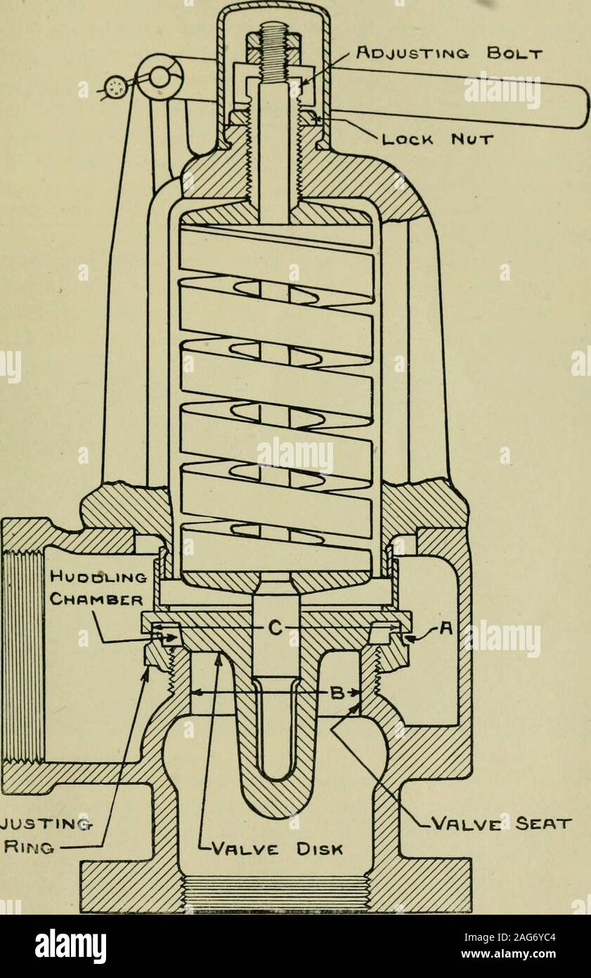
Figure 1 is a vertical cross section of a safety valve which embodies my, improvements; and I V Figs. 2 and 3 are fragmentary views showing different forms of adjustable regulating device. I is the base of the valve adapted to be secured to a boiler and provided with two concentric valve seats at E and F. The disk valve B makes a sliding fit in the lower lip of the valve hood, and has, preferably formed integrally with it, a tubular skirt J which makes a sliding fit in the base and is located just inside the inner valve seat F.
The disk valve itself is centrally perforated at L,this perforation constituting a vent from the tubular interior of the skirt J through the valve head, which contains the usual loading spring G, to the atmosphere by way of suitable apertures H. The skirt J is laterally apertured at points close to the junction between the skirt and the disk of the valve, these apertures being shown at K. Preferably, also, an annular huddling chamber is formed at N inside the inner valve The action of a safety valve comprising elements such as are exemplified in the structure shown in the drawings is as follows: Aside from the action of the huddling chamber N which may, and preferably will be provided, when the pressure in the boiler rises to the point at which the valve is set,
the disk valve B will lift slightly, and as the apertures K present themselves for egress of steam, producing pressure in the tubular interior of the skirt J and thus giving the disk B an added lifting impulse which is responded to until compression of the spring G producesequilibrium.
Preferably, for purposes of control and, regulation, the constricting device exemplified by the tapered spindle O operates pro gressively as the disk B lifts to constrict the available free vent at. L, thus enhancing the aggregate disk-lifting pressure. At the same time, as more and more of the area of apertures K is exposed, more steam will be admitted into the interior of the tubular skirt J, emphasizing the tendency to further lift of the disk, which of course always retains itself in practical equilibrium with the spring Gr. When conditions which "cause excess pressure in the boiler have passed, the disk moves downward with decreased pressure, thus increasing the vent at L and decreasing the steam egress apertures K; continued decrease in lift will finally cut down the pressure in the skirt J to such value that the valve will close quickly after blowing down. For the sake of securing a quick and sensitive pop, it is advisable to employ the huddling chamber N in conjunction with the above described controlling and regulating factors; for when the boiler pressure starts the disk B off of its seats the presence of the huddling chamber instantly brings into play additional lifting area, and insures a quick pop; and also when, upon subsidence of boiler pressure and descent of the valve disk, the auxiliary sustaining and lifting pressure inside the tubular skirt J is cut down to such a value that the valve disk closes, its final closure, which might otherwise be too abrupt, is cushioned by the momentary accumulation of pressure in the huddling chamber N which is caused by the final constriction of p the apertures K.
Furthermore, any of the above suggested methods of affecting the action of the valve may be further modified by varying the shape of the apertures K which admit steam into the central. well formed by the interior of the skirt J.
If the adjusting spindle 0 were to be eliminated and the orifice L increased in size so that there could be no appreciable pressure sustained in the tubular interior of the skirt and disk, all the parts necessary to provide a safety valve operating in the ordinary manner will remain if the huddling chamber N and vent K are present. The annular chamber N will then be the huddling chamber, and the area on the disk between the tubular skirt and the circumference of the inner seat F is the exposed area which causes pop and lift; the apertures K perform the function which the external blow-down ring in the usual type of valve performs. Such a valve will function completely as a safety valve and give lift diagrams which do not vary substan tially from those secured from valves of the prevalent commercial type. The lift may be increased by increasing the diameter of the inner seat F, this, however, not without increasing blow-down. Lifts obtainable under such conditions as are now being described are necessarily low because"of the small area which will be exposed when the valve is designed to give blow-downs of reasonably small value.
Moreover, in valves wherein a controlling spindle such as O is used, the spindle may be adjusted to such a positionthat it will take effect in conjunction with the vent L only under accumulation conditions. This implies a design such that pressure in the well will only exist in substantial value after accumulation has taken place, and imnominal seat area which lies outside the line of the seat contact at the outer seat; the steam employed to produce lift and regulation is only a small percentage of the total steam discharged, and is not quantitatively proportional to the lift and may be varied in quantity between wide limits according to requirements; the spring load area of the disk is smaller per inch of nominal valve diameter than is the case in existing valves; and the volume of the inner tubular portion or well is very large in comparison with the huddling chamber of the conventional type of valve, so large that the valve does vnot rise on the pop to a greater lift than it will sustain after the pop at the same pressure. This last mentioned feature makes a very hi h accumulation factor possible.
1. In a safety valve, a centrally perforated valve disk, concentric seats for said valve disk, of which the inner is adjacent to the central perforation in the disk, and means to constrict the effective area of egress from said inner seat as the valve disk rises.
2. In a safety valve, a base provided with concentric seats, a valve disk seating thereon, and means controlled by movement of the valve disk to constrict the effective area of egress from the inner seat as the valve disk rises.
3. In a safety-valve, a base provided with two concentric valve-seats, a disk-valve seating thereon, said disk-valve centrally perforated and provided with a tubular skirt in sliding engagement with the base inside the inner valve seat, said skirt being laterally apertured to admit pressure to its tubular interior when the disk valve is raised from its seats, and means to construct the vent provided by the central perforation in the disk-valve, as the valve rises.
l. In a safety-valve, a base provided with two concentric valve-seats, a disk-valve seating thereon, said disk valve centrally perforated and provided with a tubular skirt in sliding engagement with the base inside the inner valve seat, a huddling chamber between the inner valve seat and the tubular skirt, said skirt being laterally apertured to admit pressure to its tubular interior when the disk valve is raised from its seats.
5. In a safetywalve, a base provided with two concentric valve-seats, a disk-valve seating thereon, said disk valve centrally perforated and provided with a tubular skirt in sliding engagement with the base inside the inner valve seat, a huddling chamber between the imier valve seat and the tubular skirt, said skirt being laterally apertured to admit pressure to its tubular interior when the disk valve is raised from its seats, and means to constrict the vent provided by the central perforation in the disk valve, as the valve rises.
6. In a safety-valve, a base provided with two concentric valve-seats, a disk-valve seating thereon, said disk-valve centrally perforated and provided with a tubular skirt in sliding engagement with the base inside the inner valve seat, said skirt being laterally apertured to admit pressure to its tubular interior when the disk valve is raised from its seats, and a tapered spindle at the central perforation in the disk-valve, to constrict the vent provided thereby, as the valve rises.
7. In a safety-valve, a base provided with two concentric valve-seats, a disk-valve"seating thereon, said disk-valve centrally perforated and provided with a tubular skirt in sliding engagement with the base inside the inner valve seat, a huddling chamber between the inner valve seat and the tubular skirt, said skirt being laterally apertured to admit pressure to its tubular interior when the disk valve is raised from its seats, and a tapered spindle at the central perforation in the disk valve, to constrict the vent provided thereby, as the valve rises.
8. In a safety-valve, a base provided with two concentric valve-seats, a disk-valve seating thereon, said disk-valve centrally perforated and provided with a tubular skirt in sliding engagement with the base inside the

Safety Relief Valve are normally used for liquid service, although safety valves may also be used. Ordinary relief valves do not have an accentuated huddling chamber nor a regular ring for varying or adjusting blowdown they therefore operate with a relatively lazy motion, slowly opening or closing as pressure increases or decreases. Such reliving action affords suitable protection for vessels or systems where there is no need for instaeous release of large volumes, and where sufficient leeway is provided between the design pressure and operating pressure in the system.

As soon as mankind was able to boil water to create steam, the necessity of the safety device became evident. As long as 2000 years ago, the Chinese were using cauldrons with hinged lids to allow (relatively) safer production of steam. At the beginning of the 14th century, chemists used conical plugs and later, compressed springs to act as safety devices on pressurised vessels.
Early in the 19th century, boiler explosions on ships and locomotives frequently resulted from faulty safety devices, which led to the development of the first safety relief valves.
In 1848, Charles Retchie invented the accumulation chamber, which increases the compression surface within the safety valve allowing it to open rapidly within a narrow overpressure margin.
Today, most steam users are compelled by local health and safety regulations to ensure that their plant and processes incorporate safety devices and precautions, which ensure that dangerous conditions are prevented.
The principle type of device used to prevent overpressure in plant is the safety or safety relief valve. The safety valve operates by releasing a volume of fluid from within the plant when a predetermined maximum pressure is reached, thereby reducing the excess pressure in a safe manner. As the safety valve may be the only remaining device to prevent catastrophic failure under overpressure conditions, it is important that any such device is capable of operating at all times and under all possible conditions.
Safety valves should be installed wherever the maximum allowable working pressure (MAWP) of a system or pressure-containing vessel is likely to be exceeded. In steam systems, safety valves are typically used for boiler overpressure protection and other applications such as downstream of pressure reducing controls. Although their primary role is for safety, safety valves are also used in process operations to prevent product damage due to excess pressure. Pressure excess can be generated in a number of different situations, including:
The terms ‘safety valve’ and ‘safety relief valve’ are generic terms to describe many varieties of pressure relief devices that are designed to prevent excessive internal fluid pressure build-up. A wide range of different valves is available for many different applications and performance criteria.
In most national standards, specific definitions are given for the terms associated with safety and safety relief valves. There are several notable differences between the terminology used in the USA and Europe. One of the most important differences is that a valve referred to as a ‘safety valve’ in Europe is referred to as a ‘safety relief valve’ or ‘pressure relief valve’ in the USA. In addition, the term ‘safety valve’ in the USA generally refers specifically to the full-lift type of safety valve used in Europe.
Pressure relief valve- A spring-loaded pressure relief valve which is designed to open to relieve excess pressure and to reclose and prevent the further flow of fluid after normal conditions have been restored. It is characterised by a rapid-opening ‘pop’ action or by opening in a manner generally proportional to the increase in pressure over the opening pressure. It may be used for either compressible or incompressible fluids, depending on design, adjustment, or application.
Safety valves are primarily used with compressible gases and in particular for steam and air services. However, they can also be used for process type applications where they may be needed to protect the plant or to prevent spoilage of the product being processed.
Relief valve - A pressure relief device actuated by inlet static pressure having a gradual lift generally proportional to the increase in pressure over opening pressure.
Relief valves are commonly used in liquid systems, especially for lower capacities and thermal expansion duty. They can also be used on pumped systems as pressure overspill devices.
Safety relief valve - A pressure relief valve characterised by rapid opening or pop action, or by opening in proportion to the increase in pressure over the opening pressure, depending on the application, and which may be used either for liquid or compressible fluid.
In general, the safety relief valve will perform as a safety valve when used in a compressible gas system, but it will open in proportion to the overpressure when used in liquid systems, as would a relief valve.
Safety valve- A valve which automatically, without the assistance of any energy other than that of the fluid concerned, discharges a quantity of the fluid so as to prevent a predetermined safe pressure being exceeded, and which is designed to re-close and prevent further flow of fluid after normal pressure conditions of service have been restored.

Safety valve is a valve that act as a protection of equipment from exploding or damaging and it is mainly installed in pressure vessels such as chemical plants, electric power boilers and gas storage tanks.
Safety Valve is a type of valve that automatically actuates when the pressure of inlet side of the valve increases to a predetermined pressure, to open the valve disc and discharge the fluid (steam or gas ) ; and when the pressure decreases to the prescribed value, to close the valve disc again. Safety valve is so-called a final safety device which controls the pressure and discharges certain amount of fluid by itself without any electric power support.

One of the main reasons I have found for chattering of a safety valve is improper line sizing. Specifically, the inlet line to the safety valve. What"s happening is if the system sees an overpressure the safety valve opens (fully, assumes a true safety valve with huddling chamber). The valve will remain open as long as it is at app. 90% full capacity. If the line sizing restricts this flow the valve closes. Pressure builds, it opens fully. The process is cyclic and the rapid opening/closing prematurely wears down the valve nozzle and seat.
The valve pops on static pressure increase, the flow losses cause it to reseat before the system pressure (at the source has cleared) and the cycle repeats...
look for reducers, excessive bends and elbows, and valving in the inlet line. also look for long piping runs beteen the relief valve and the vessel or the pipe being protected.
I also encounter a lot of general industry plants that try to operate at or very near to the safety valve settings. It"s very common for the unknowing to select a safety valve that"s set for their operating pressure, and have it "feather". RE: Pressure Valve Chattering
you can take into account line and minor losses in system where PRV"s are installed, it would not be practicle to minimize line and minor losses only to cut the pressure loss you saved with the PRV valve.....
To take these into account you have to properly size the valve(S). I hinted to a big blunder I see often. A PRV may consist of more than one valve depending on what you are trying to accomplish....
Why not use a pilot operated PSV with the sensor located on the vessel (or whatever it is you"re trying to protect)? That should help with pressure drop on the inlet side. This may stop the chattering, but you may still have a problem if the line is too small, ie, the pipe and valve won"t pass enough fluid to bring the pressure down fast enough. RE: Pressure Valve Chattering
Or......if this is a steam pressure reducing valve, check out the catalog information for the Watts Model 152A which has an anti-chatter adjusting screw on the side. RE: Pressure Valve Chattering
Both Farris Engineering and Dresser Consolidated Troubleshooting Charts refer to Undersized Inlet Piping as a major cause of Chatter. A quote from Crosby, "A valve should never be installed on a fitting having a smaller inside diameter than the inlet connection of the valve."
According to API RP576, 5.2.c., "Improper or lengthy piping to the PRV inlet…can cause a PRV to chatter. The pressure under the seat may become great enough to open the PRV. However, as soon as the flow is established, the built-up pressure drop in the connecting piping may be so great that the pressure under the seat falls and allows the valve to close. A cycle of opening and closing may develop, become rapid, and subject the PRV Seating Surfaces to severe hammering, which damages the seating surfaces, sometimes beyond repair."
If you think about it logically, reducing the inlet piping or making it excessively long both have the same effect on the operation of a PRV as placing a large, high capacity PRV in a low volume application (oversizing). Basically there is insufficient volume to maintain the reaction force in the PRV Huddling Chamber necessary to overcome spring force.
The PRV is designed for a flow range, if the system cannot deliver that flow then the valve is oversized, no matter what the diameter and if you design only on daimeter without understanding the system, it is bound to fail...Volume of flow through the valve has nothing to do with its operation, its only the pressure that performs the work to modulate the valve.
I understand that Site Specific Engineering Solutions are preferable to a CODE which seeks consensus. However,I have been Setting & Testing Pressure Relief Valves for ASME Sec. I, Steam and for ASME Sec. VIII Steam, Air/Gas and Liquid Service for 30 years. I have tested on a range of Test Benches from small Test Rigs with no volume to Test Benches with 100 cu ft Test Vessels as well as on Power Boilers upto 2970 psi with Live Steam. My experience with the Performance of PRVs tested on Low Volume and then placed in High Flow Service Applications proves to me that Flow is as important to PRV Performance as Pressure.
I have known many of the members of ASME Sub-Committee Safety Valve Requirements for years, many are employees of PRV Manufacturers and all are very knowledgable. They take their Committee Work seriously and have written the requirements to reflect their collective experience.
All my comments are directed toward Pressure Relief Valves. I have no practical experience in Pressure Reducing applications and I began to wonder if that is why we seem to be in disagreement over some very basic issues.
For years the ASME Code referred to Safety-Relief Valves (SRV), but recently the National Board Inspection Code has attempted to change the term to Pressure Relief Valve (PRV).
sorry for the confusion, I reread your posts too....I was DEFINATELY not talking steam!!!! Nor relief valves.... LOL it is confusing and I wish we engineers would settle on terminology....I was talking pressure reducing service for fluids.....I was wrong not to quantify my response.....my comments only go for fluids for whoever is reading.....
We are the leading manufacturers and suppliers of Air Release Valves,which are produced from a very high quality raw materials sourced from the most renowned vendors of the industry. The product is available to the clients at reasonable prices. It is composed of cast iron and cast steel. They can automatically release accumulated air and gases from the fluid system while the system is working.
We have gain expertise in Manufacturing and Supplying Air Vent Valve of best quality. Procuring raw material from trustworthy agents, our expert engineers use latest technology and high-grade tools to fabricate them. Our products are highly demanded for the reliability that our customers gains from us. Before dispatching these products we make these products go through various quality-check process ensuring high quality. We also provide customization facility to our esteemed customers in accordance with their needs and requirements.
Direct mechanical lever operated ball float valves, single or double ported in C.I., C.S. and SS, non metallic constructions operating mechanism is specially designed to be mounted on all types of tank equipment and serves the purpose of a liquid level controlling. Automatic filling and maintaining is done at the said levels.
Direct mechanical lever operated ball float valves, single ordouble ported in Brass, C.I.,C.S., and SS, non metallic constructions operating mechanism is specially designed to be mounted onall types of tank equipment and serves the purpose olevel controlling. Automatic filling and maintaining is doneat the said levels.
Our company is engaged in the manufacturing of Safety Valves, which guarantee to reduce the over pressure in steam,gas or liquid. Available in different sizes, these products can be availed from us at a very reasonable price. We also have a expert team, which deals with the customization of products according to the needs of our clients.
Available with us is a wide range of qualitative Safety Valvethat are used to control high pressures. These valves having a larger applications area are used in pressure vessels, reactors and pipelines. Offered product works automatically if the pressure exceeds the standard applied limits. These valves works as a guard to capital instrument ensuring no damage at all. We manufacture these valves using latest technology and high-grade tools ensuring best outcome to our valued patrons.
We are a market-leading firm engaged in Manufacturing, Supplying and Exporting premium quality PressureRelief Valve. We manufacture these valves using excellent quality raw material procured from certified and authentic vendor-base. Our vast infrastructure and professional experts enabled us to produce these qualitative valves on a very large scale to meet the high demands country-wide. We also provide customization facilities to our customers as per their requirements and demands
Being the leading manufacturers and exporters of Air Vent Valves,we ensure that the product delivered to the customer is of very high quality and the raw material is purchased from reliable vendors. The product is cost effective and is delivered to the customer on time. This product is applied on systems transporting liquids with little solid content. If the liquid used is other than water, then the specific gravity of the liquid must be taken into consideration.
We are a market-leading firm engaged in Manufacturing, Supplying and Exporting premium quality PressureRelief Valve. We manufacture these valves using excellent quality raw material procured from certified and authentic vendor-base. Our vast infrastructure and professional experts enabled us to produce these qualitative valves on a very large scale to meet the high demands country-wide. We also provide customization facilities to our customers as per their requirements and demands
VEEKAY Pressure and Vacuum Relief Valves have been designed for atmospheric and low Pressure Storage Tanks Containing volatile products to maintain the tank Pressure and Vacuum with in pre-determined, thus prevent the tanks from any disaster like explosion due to increase of Tank Pressure and implosion due to decrease in Vacuum during thermal cycling or while filling or emptying the storage tanks. PV Valves assists to conserve the fluid by reducing the evaporation loss and provide clean environment.
Being the leading manufacturers and exporters of Air Vent Valves,we ensure that the product delivered to the customer is of very high quality and the raw material is purchased from reliable vendors. The product is cost effective and is delivered to the customer on time. This product is applied on systems transporting liquids with little solid content. If the liquid used is other than water, then the specific gravity of the liquid must be taken into consideration.
A globe valve, different from ball valve, is a type of valve used for regulating flow in a pipeline, consisting of a movable plug or disc element and a stationary ring seat in a generally spherical body
We are a market-leading firm engaged in Manufacturing, Supplying and Exporting premium quality Safety Relief Valve. We manufacture these valves using excellent quality raw material procured from certified and authentic vendor-base. Our vast infrastructure and professional experts enabled us to produce these qualitative valves on a very large scale to meet the high demands country-wide. We also provide customization facilities to our customers as per their requirements and demands
SAFETY RELIEF VALVESVeeKay manufactures 2 types of Pressure releasing (discharging) valves as perthe ASME Code VIII and API RP – 526. Both safety valve and safety Reliefvalves of the spring loaded type are similar in external appearance and bothserve the broad general purpose or limiting fluids (liquid or gases) pressures bydischarging some of the pressurized liquid or gas. For very high temperaturesafety and safety relief valves can be used with finned bonnet. VeeKay can alsodesign and manufacture custom made safety relief and safety valves to meetspecial requirements. VeeKay safety and safety relief valves are available insizes from ¼” to 14”.Op. Pre and Temp : 0-100 Kg/Cm 2 and 0-500 º CVeeKay Safety Relief Valves are normally used for liquid service, althoughsafety valves may also be used. Ordinary relief valves do not have anaccentuated huddling chamber or a regular ring for varying or adjusting blowdown they therefore operate with a relatively lazy motion, slowly opening orclosing as pressure increases or decreases. Such relieving action affords suitableprotection for vessels or systems where there is no need for instaneous releaseof large volumes, and where sufficient leeway is provided between the designpressure and the operating pressure in the system.
VEEKAY Self Actuating, Internally Sensed Pilot & Piston operated, Direct Spring & Diaphragm Actuated, Top & Bottom Guided Pressure Reducing Valve with screwed / Flanged End connection.
VEEKAY Roboter operated pressure reducing valve can be used for many Industrial application where reducing pressure of steam, gases and other fluids to be kept constant with high flow.
Being the leading manufacturers and exporters of Air Vent Valves,we ensure that the product delivered to the customer is of very high quality and the raw material is purchased from reliable vendors. The product is cost effective and is delivered to the customer on time. This product is applied on systems transporting liquids with little solid content. If the liquid used is other than water, then the specific gravity of the liquid must be taken into consideration.
We are manufacturing and exporting Pressure Cum Vacuum Relief Valves, Breather Valves, Vacuum Relief Valves, Safety Valves, Pressure Relief Valves to all over the world. Our brand Name : Veekay - Made in INDIA is well familiar in the industry.

A safety valve is a valve that acts as a fail-safe. An example of safety valve is a pressure relief valve (PRV), which automatically releases a substance from a boiler, pressure vessel, or other system, when the pressure or temperature exceeds preset limits. Pilot-operated relief valves are a specialized type of pressure safety valve. A leak tight, lower cost, single emergency use option would be a rupture disk.
Safety valves were first developed for use on steam boilers during the Industrial Revolution. Early boilers operating without them were prone to explosion unless carefully operated.
Vacuum safety valves (or combined pressure/vacuum safety valves) are used to prevent a tank from collapsing while it is being emptied, or when cold rinse water is used after hot CIP (clean-in-place) or SIP (sterilization-in-place) procedures. When sizing a vacuum safety valve, the calculation method is not defined in any norm, particularly in the hot CIP / cold water scenario, but some manufacturers
The earliest and simplest safety valve was used on a 1679 steam digester and utilized a weight to retain the steam pressure (this design is still commonly used on pressure cookers); however, these were easily tampered with or accidentally released. On the Stockton and Darlington Railway, the safety valve tended to go off when the engine hit a bump in the track. A valve less sensitive to sudden accelerations used a spring to contain the steam pressure, but these (based on a Salter spring balance) could still be screwed down to increase the pressure beyond design limits. This dangerous practice was sometimes used to marginally increase the performance of a steam engine. In 1856, John Ramsbottom invented a tamper-proof spring safety valve that became universal on railways. The Ramsbottom valve consisted of two plug-type valves connected to each other by a spring-laden pivoting arm, with one valve element on either side of the pivot. Any adjustment made to one of valves in an attempt to increase its operating pressure would cause the other valve to be lifted off its seat, regardless of how the adjustment was attempted. The pivot point on the arm was not symmetrically between the valves, so any tightening of the spring would cause one of the valves to lift. Only by removing and disassembling the entire valve assembly could its operating pressure be adjusted, making impromptu "tying down" of the valve by locomotive crews in search of more power impossible. The pivoting arm was commonly extended into a handle shape and fed back into the locomotive cab, allowing crews to "rock" both valves off their seats to confirm they were set and operating correctly.
Safety valves also evolved to protect equipment such as pressure vessels (fired or not) and heat exchangers. The term safety valve should be limited to compressible fluid applications (gas, vapour, or steam).
For liquid-packed vessels, thermal relief valves are generally characterized by the relatively small size of the valve necessary to provide protection from excess pressure caused by thermal expansion. In this case a small valve is adequate because most liquids are nearly incompressible, and so a relatively small amount of fluid discharged through the relief valve will produce a substantial reduction in pressure.
Flow protection is characterized by safety valves that are considerably larger than those mounted for thermal protection. They are generally sized for use in situations where significant quantities of gas or high volumes of liquid must be quickly discharged in order to protect the integrity of the vessel or pipeline. This protection can alternatively be achieved by installing a high integrity pressure protection system (HIPPS).
In the petroleum refining, petrochemical, chemical manufacturing, natural gas processing, power generation, food, drinks, cosmetics and pharmaceuticals industries, the term safety valve is associated with the terms pressure relief valve (PRV), pressure safety valve (PSV) and relief valve.
The generic term is Pressure relief valve (PRV) or pressure safety valve (PSV). PRVs and PSVs are not the same thing, despite what many people think; the difference is that PSVs have a manual lever to open the valve in case of emergency.
Relief valve (RV): an automatic system that is actuated by the static pressure in a liquid-filled vessel. It specifically opens proportionally with increasing pressure
Pilot-operated safety relief valve (POSRV): an automatic system that relieves on remote command from a pilot, to which the static pressure (from equipment to protect) is connected
Low pressure safety valve (LPSV): an automatic system that relieves static pressure on a gas. Used when the difference between the vessel pressure and the ambient atmospheric pressure is small.
Vacuum pressure safety valve (VPSV): an automatic system that relieves static pressure on a gas. Used when the pressure difference between the vessel pressure and the ambient pressure is small, negative and near to atmospheric pressure.
Low and vacuum pressure safety valve (LVPSV): an automatic system that relieves static pressure on a gas. Used when the pressure difference is small, negative or positive and near to atmospheric pressure.
In most countries, industries are legally required to protect pressure vessels and other equipment by using relief valves. Also, in most countries, equipment design codes such as those provided by the ASME, API and other organizations like ISO (ISO 4126) must be complied with. These codes include design standards for relief valves and schedules for periodic inspection and testing after valves have been removed by the company engineer.
Today, the food, drinks, cosmetics, pharmaceuticals and fine chemicals industries call for hygienic safety valves, fully drainable and Cleanable-In-Place. Most are made of stainless steel; the hygienic norms are mainly 3A in the USA and EHEDG in Europe.
The first safety valve was invented by Denis Papin for his steam digester, an early pressure cooker rather than an engine.steelyard" lever a smaller weight was required, also the pressure could easily be regulated by sliding the same weight back and forth along the lever arm. Papin retained the same design for his 1707 steam pump.Greenwich in 1803, one of Trevithick"s high-pressure stationary engines exploded when the boy trained to operate the engine left it to catch eels in the river, without first releasing the safety valve from its working load.
Although the lever safety valve was convenient, it was too sensitive to the motion of a steam locomotive. Early steam locomotives therefore used a simpler arrangement of weights stacked directly upon the valve. This required a smaller valve area, so as to keep the weight manageable, which sometimes proved inadequate to vent the pressure of an unattended boiler, leading to explosions. An even greater hazard was the ease with which such a valve could be tied down, so as to increase the pressure and thus power of the engine, at further risk of explosion.
Although deadweight safety valves had a short lifetime on steam locomotives, they remained in use on stationary boilers for as long as steam power remained.
Weighted valves were sensitive to bouncing from the rough riding of early locomotives. One solution was to use a lightweight spring rather than a weight. This was the invention of Timothy Hackworth on his leaf springs.
These direct-acting spring valves could be adjusted by tightening the nuts retaining the spring. To avoid tampering, they were often shrouded in tall brass casings which also vented the steam away from the locomotive crew.
The Salter coil spring spring balance for weighing, was first made in Britain by around 1770.spring steels to make a powerful but compact spring in one piece. Once again by using the lever mechanism, such a spring balance could be applied to the considerable force of a boiler safety valve.
The spring balance valve also acted as a pressure gauge. This was useful as previous pressure gauges were unwieldy mercury manometers and the Bourdon gauge had yet to be invented.
Paired valves were often adjusted to slightly different pressures too, a small valve as a control measure and the lockable valve made larger and permanently set to a higher pressure, as a safeguard.Sinclair for the Eastern Counties Railway in 1859, had the valve spring with pressure scale behind the dome, facing the cab, and the locked valve ahead of the dome, out of reach of interference.
In 1855, John Ramsbottom, later locomotive superintendent of the LNWR, described a new form of safety valve intended to improve reliability and especially to be tamper-resistant. A pair of plug valves were used, held down by a common spring-loaded lever between them with a single central spring. This lever was characteristically extended rearwards, often reaching into the cab on early locomotives. Rather than discouraging the use of the spring lever by the fireman, Ramsbottom"s valve encouraged this. Rocking the lever freed up the valves alternately and checked that neither was sticking in its seat.
A drawback to the Ramsbottom type was its complexity. Poor maintenance or mis-assembly of the linkage between the spring and the valves could lead to a valve that no longer opened correctly under pressure. The valves could be held against their seats and fail to open or, even worse, to allow the valve to open but insufficiently to vent steam at an adequate rate and so not being an obvious and noticeable fault.Rhymney Railway, even though the boiler was almost new, at only eight months old.
Naylor valves were introduced around 1866. A bellcrank arrangement reduced the strain (percentage extension) of the spring, thus maintaining a more constant force.L&Y & NER.
All of the preceding safety valve designs opened gradually and had a tendency to leak a "feather" of steam as they approached "blowing-off", even though this was below the pressure. When they opened they also did so partially at first and didn"t vent steam quickly until the boiler was well over pressure.
The quick-opening "pop" valve was a solution to this. Their construction was simple: the existing circular plug valve was changed to an inverted "top hat" shape, with an enlarged upper diameter. They fitted into a stepped seat of two matching diameters. When closed, the steam pressure acted only on the crown of the top hat, and was balanced by the spring force. Once the valve opened a little, steam could pass the lower seat and began to act on the larger brim. This greater area overwhelmed the spring force and the valve flew completely open with a "pop". Escaping steam on this larger diameter also held the valve open until pressure had dropped below that at which it originally opened, providing hysteresis.
These valves coincided with a change in firing behaviour. Rather than demonstrating their virility by always showing a feather at the valve, firemen now tried to avoid noisy blowing off, especially around stations or under the large roof of a major station. This was mostly at the behest of stationmasters, but firemen also realised that any blowing off through a pop valve wasted several pounds of boiler pressure; estimated at 20 psi lost and 16 lbs or more of shovelled coal.
Pop valves derived from Adams"s patent design of 1873, with an extended lip. R. L. Ross"s valves were patented in 1902 and 1904. They were more popular in America at first, but widespread from the 1920s on.
Although showy polished brass covers over safety valves had been a feature of steam locomotives since Stephenson"s day, the only railway to maintain this tradition into the era of pop valves was the GWR, with their distinctive tapered brass safety valve bonnets and copper-capped chimneys.
Developments in high-pressure water-tube boilers for marine use placed more demands on safety valves. Valves of greater capacity were required, to vent safely the high steam-generating capacity of these large boilers.Naylor valve) became more critical.distilled feedwater and also a scouring of the valve seats, leading to wear.
High-lift safety valves are direct-loaded spring types, although the spring does not bear directly on the valve, but on a guide-rod valve stem. The valve is beneath the base of the stem, the spring rests on a flange some height above this. The increased space between the valve itself and the spring seat allows the valve to lift higher, further clear of the seat. This gives a steam flow through the valve equivalent to a valve one and a half or twice as large (depending on detail design).
The Cockburn Improved High Lift design has similar features to the Ross pop type. The exhaust steam is partially trapped on its way out and acts on the base of the spring seat, increasing the lift force on the valve and holding the valve further open.
To optimise the flow through a given diameter of valve, the full-bore design is used. This has a servo action, where steam through a narrow control passage is allowed through if it passes a small control valve. This steam is then not exhausted, but is passed to a piston that is used to open the main valve.
There are safety valves known as PSV"s and can be connected to pressure gauges (usually with a 1/2" BSP fitting). These allow a resistance of pressure to be applied to limit the pressure forced on the gauge tube, resulting in prevention of over pressurisation. the matter that has been injected into the gauge, if over pressurised, will be diverted through a pipe in the safety valve, and shall be driven away from the gauge.
There is a wide range of safety valves having many different applications and performance criteria in different areas. In addition, national standards are set for many kinds of safety valves.
Safety valves are required on water heaters, where they prevent disaster in certain configurations in the event that a thermostat should fail. Such a valve is sometimes referred to as a "T&P valve" (Temperature and Pressure valve). There are still occasional, spectacular failures of older water heaters that lack this equipment. Houses can be leveled by the force of the blast.
Pressure cookers usually have two safety valves to prevent explosions. On older designs, one is a nozzle upon which a weight sits. The other is a sealed rubber grommet which is ejected in a controlled explosion if the first valve gets blocked. On newer generation pressure cookers, if the steam vent gets blocked, a safety spring will eject excess pressure and if that fails, the gasket will expand and release excess pressure downwards between the lid and the pan. Also, newer generation pressure cookers have a safety interlock which locks the lid when internal pressure exceeds atmospheric pressure, to prevent accidents from a sudden release of very hot steam, food and liquid, which would happen if the lid were to be removed when the pan is s


 8613371530291