
hydraulic safety valve symbol factory
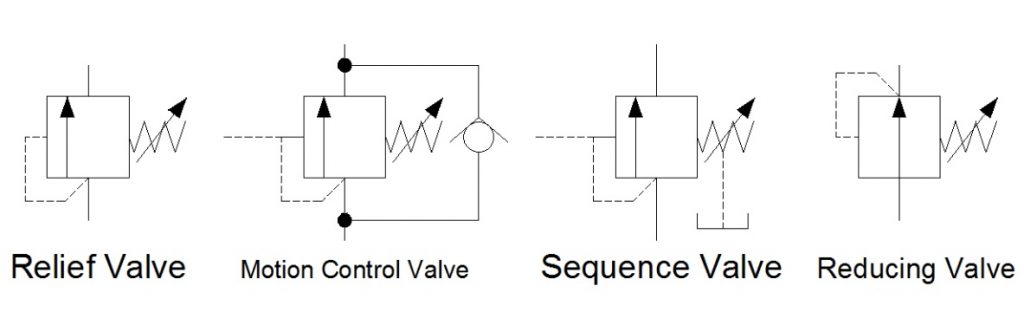
In Hydraulic Symbology 101 (read it here first), I covered the basic square used for pressure valves and also showed the most stripped-down versions of the two most commonly used pressure valve symbols, the relief valve and the pressure reducing valve. In this edition of Hydraulic Symbology, I’m going to cover the four primary pressure valves; the relief valve, motion control valve, sequence valve and reducing valve. Each is based on the same square symbol but are used quite differently in both circuits and real-life function.
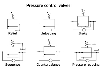
Shown below are the quartet referenced from the same angle as each other. Each shows the basic square with a vertical arrow, abreast of a pilot line to the left and a spring to the right. The dashed line stands for a pilot signal, which is a fluid column of pressure energy used to push or act upon other components internal to the valve. The relief valve is normally closed (non-flowing). As pressure rises in the bottom port, energy pushes around to the pilot line to the left, but the valve is still closed. As the pressure continues to increase, the force pushing against the left side of the arrow starts to overcome the spring force applied from the right. When pilot pressure creates enough force, it can overcome spring pressure to slowly open the valve.
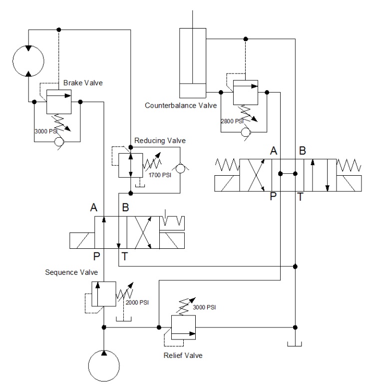
The below example shows a circuit with all four types of pressure valves used. It looks like a lot going on, but I’m going to break them all down one by one so they make sense. The relief valve teed into the right after the pump is drawn just as the relief valve above, and it operates under the same principle. The spring is pushing the valve closed with 3,000 psi of force, and in this circuit, it acts as the maximum limit pump pressure can achieve before being exhausted to tank.
Sequence valves are not much different from relief valves, and this is at once obvious by their similar appearance. This sequence valve downstream of the pump is exactly the same as the relief save for the drain line and reduced pressure setting. A sequence valve is purposed to provide a secondary flow path which occurs in sequence to a parallel function. In other words, when the cylinder in this application extends to the end of stroke, pressure will rise immediately. When pressure hits 2,000 psi, our sequence valve opens, diverting all pump flow to rotate the motor while the cylinder remains stalled and as long as its directional valve remains energized.
The sequence valve drain line is required to keep the valve’s performance consistent. Because the sequence valve experiences pressure on both ports, internal leakage allows pressure buildup inside the spring chamber which is additive to spring pressure. Without a drain, the pressure setting could rise or the valve could even lock up altogether. The key difference between a sequence valve and relief valve is the existence of this drain. A sequence valve makes an outstanding relief valve, in fact.
The pressure reducing valve is plumbed in just past the directional valve in the B-port. You’ll notice immediately how different this valve is than the others, and the extra astute will have noticed two differences, actually. The pilot line is drawn differently, this time showing its pressure signal originating downstream of the valve. This important contrast allows the valve to reduce downstream pressure to protect the actuator or sub-circuit beyond.
The reducing valve also differs in that it is normally flowing in its neutral state. Fluid is free to pass and allow the motor to spin, and not until downstream pressure from the motor rises to above the 1,700 psi setting of the valve does is start to close. The pilot line senses downstream pressure and starts to move the arrow to the right, choking flow to the motor. This reduced flow also reduces pressure, but it does so smoothly and with little drop in velocity. The effect is that downstream pressure is simply reduced.
You’ll notice in this example, there is also a check valve allowing flow to bypass the reducing valve altogether. This ensures the motor will experience little or no backpressure when it rotates in the opposite direction. Sometimes the reverse-flow check valve is not required, but it makes for good practice.
The last pressure valve to be discussed today is the motion control valve, which in my example is broken down into the brake valve and the counterbalance valve. The brake valve is used in motor applications as seen above. The valve is also very similar to the relief valve in design, and in fact, could still be used as one (as is the case for all pressure valve aside from the reducing valve). The reverse flow check valve allows free flow into the motor, allowing it to freely spin clockwise when the directional valve is left in its current detented position.
When the directional valve is reversed, however, the check valve blocks free flow and oil must now flow through the brake valve. This valve, you’ll notice, has two separate pilot lines merging at the same point on the valve. It has the same direct acting pilot line that rounds the corner, but there is an additional pilot source drawn from the opposite port of the motor. These dual pilot sources add interesting functionality to the brake valve in that it is both internally and externally piloted.
The internal, direct-acting signal will ensure the motor won’t move until a combination of load and pump pressure pushes through the motor to the tune of 3,000 psi. This allows the motor to stay “braked” while pump flow is non-existent. However, a direct-acting brake control valve is an inefficient method to control motion.
This valve has a trick up its sleeve — the surface area the external pilot works against is larger than the area of the direct acting side. The ratio of areas is often 4:1 but can be upwards of 8:1. The result is the pilot pressure needs to a quarter of work pressure, reducing energy lost to the brake valve. The brake valve is essentially braking to the tune of 3,000 psi, but opening to provide flow when the opposite port sees 375-750 psi. The valve uses pilot pressure as permission to open and allow flow, preventing unintended movement of the motor.
Lastly, we arrive at the motion control valve labelled counterbalance valve. It’s typically one and the same as a brake valve but used in cylinder applications. This example shows a relief valve set to 2,800 psi and is plumbed to the cap port of the cylinder. The reverse flow check valve ensures the cylinder will extend with little pressure drop, but when the directional valve is placed back in neutral, the counterbalance valve remains closed so the cylinder will not accidentally retract.
The counterbalance valve also has a pilot ratio enabling the valve to open once it senses pilot energy from the rod port, preventing accidental retraction. Counterbalance valves also work well on the rod port of a cylinder, which prevents overrunning loads as a cylinder moves “over center,” which is a condition of pulling forces on the rod.
Both examples of these motion control valves could have been employed with spring chamber drain ports, just as with the sequence valve. The drain keeps the spring chamber free from additional pressure, but in the case of this circuit, the open line to the reservoir through directional valves is enough to prevent excessive pressure. It’s when both ports of the pressure valve are continuously pressurized that a drain or vent is absolutely required.
There are many variations of pressure valves not covered here, but those will be discussed in a later episode. In Hydraulic Symbology 204, I’ll cover the essentials of flow control valves, including how they’re drawn and where they’re used.
The words flow control valves broadly describe any hydraulic component capable of diminishing fluid volume downstream of itself relative to upstream. It goes without saying a flow control valve only reduces flow since the laws of nature remain unbroken. The method of varying flow varies considerably and depending on the choice of valve and its location, the effect can be substantial.
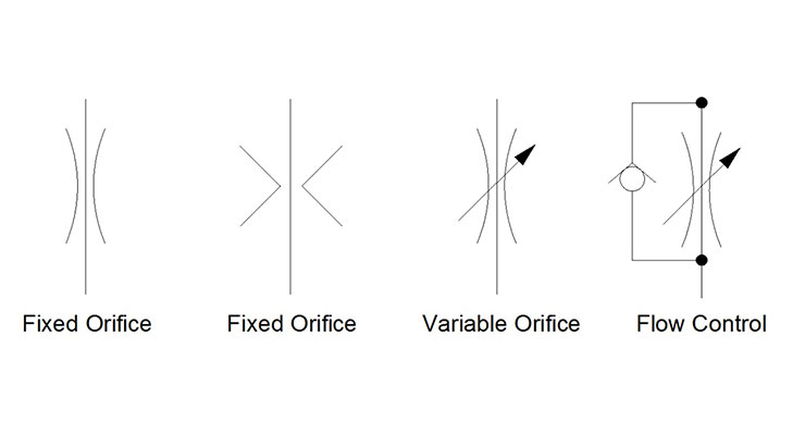
Draw the fixed orifice in one of two ways as shown in Figure 1. The first, and most common method, shows the flow path surrounded by outward facing, gentle arcs. They signify a smooth compression of the fluid, but in reality, hydraulic components are rarely honed so smoothly. The second symbol with inward facing vertices depicts the less common method of drawing a fixed orifice, although it’s the one I personally prefer.
Fixed orifices are used typically used for factory settings in pumps, manifolds and valves, but offer no user adjustability. A variable orifice provides a method to control the size of the gap between the needle and its seat, thus changing the flow rate through itself. The symbol simply adds the diagonal arrow depicting adjustability in fluid power symbols. As with most symbology, the method varying flow in the physical valve is otherwise irrelevant in regard to the symbol. Additionally, neither does the adjustable symbol guarantee that flow rate will even be adjusted if there is no upstream provision to reduce or bypass flow otherwise allocated to the valve. This is, after all, positive displacement we’re talking about, and in a system with a fixed pump, fluid must go somewhere.
Classic hydraulic theory teaches us they’re not flow control valves unless and until there is a reverse flow check valve, such as in the last example of Figure 1. The check valve blocks upward flow through this valve symbol, pressing the ball into the seat when flow exists at the bottom port. Reverse flow allows the ball to lift and bypass the check valve, although a good portion of flow will still pass through the orifice, as pressure drop through both the orifice and check valve will be exactly equal to each other. The diagonal arrow shows us this flow control valve is a variable flow rate.
Although this series is focused on symbols more than any principles of fluid power, it’s important to understand the relationship with pressure and flow. In any circuit where a restriction, orifice or flow control reduces flow, pressure increases. Also, in any circumstance where downstream pressure is high, the potential to flow through a metering device is reduced. The important term to remember is pressure drop, which is a comparison of upstream and downstream pressure through an object. Any change in flow or pressure drop can have consequence, either positive or negative, on system performance.
The four symbols covered thus far represent valves that will flow at a rate dictated by pressure drop through them, and should downstream pressure rise or fall, flow will change inversely proportional. To get around this problem, a concept called pressure compensation was created, and it uses a clever technique to encourage flow when downstream pressure increases, thereby allowing a stable flow rate regardless of load or supply pressure fluctuations.
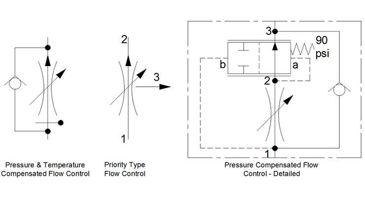
The first symbol in Figure 2 depicts the simplified version of a pressure and temperature compensated flow control. This symbol comprises the orifice arcs, the variable arrow and reverse-flow check valve, just as with a standard flow control. However, the addition of the upward facing arrowhead tells us it is pressure compensated. I cannot tell you the etymology related to this choice of graphic, but it’s standard practice, nevertheless. More easily understood is the symbol for temperature compensation, which expresses itself as a sideways thermometer. Temperature compensation could also be called viscosity compensation because it’s just a feature that allows the valve to manage flow rate despite varying oil viscosity.
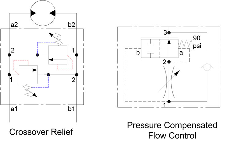
The final symbol showing a detailed representation of a pressure compensated flow control is where things get complicated, but if you stick with me, you’ll understand. The variable orifice and check valve are self-explanatory, but the compensator symbol added downstream has a lot going on. Port 1 upstream of the orifice is connected to the b-side envelope of the compensator, which shows the “T” symbols to block flow at both ports. Port 2 is connected downstream of the variable orifice and feeds its pilot line to the b-side envelope of the compensator, but this shows it as normally flowing in neutral. Port 3 of the valve simply connects the whole assembly and bypasses the fun bits and provide free flow in reverse; a true flow control.
The compensator is shown as a 2-position valve, but it’s more of an infinitely variable spool valve that meters between flowing more or flowing less. The compensator is offset by a spring that provides 90 psi of effort, additive to whatever is transmitted from port 2. When flow occurs through the valve, the compensator compares pressure at the ports 1 and 2 of the variable orifice. Pressure will always be higher at port 1, so pilot pressure forces the compensator closed until port 1 pressure matches the 90-psi spring valve. Flow through the variable orifice will always represent whatever 90-psi worth of pressure drop will achieve through itself, regardless of its setting.
If we use an example of a pump capable of 12 gpm and a 3,000-psi compensator or relief valve, the pressure at port 1 will see 3,000 psi. Let’s assume we want 10 gpm at 90-psi pressure drop, so we adjust our orifice to suit. Because the compensator is installed and wants to see a 90-psi difference between ports 1 and 2, the pressure at port 2 will close the compensator to block flow until port 2 pressure is 2,910 psi. At this point, 10 gpm will be flowing through the valve while the pump is either dumping 2 gpm over the relief valve or reducing its swashplate angle slightly.
If downstream pressure rises to 1,500 psi, pilot pressure at port 2 will increase, forcing the valve open and compensating for the downstream pressure increase. What would normally result in less flow potential over a given “Delta P,” now results in the compensator opening to reduce downstream backpressure. The compensator works like a pressure reducing valve in reverse; as pressure increases, it opens wider to allow more flow that would be normally lost to reduced pressure drop.
Pressure compensators can be added to any valve of a hydraulic circuit that controls flow rate, including proportional valves. Later in this series, I’ll talk about some advanced concepts based on pressure compensators, which are sometimes called “hydrostats.” Check back soon for the next article in this series, this time covering the symbols of hydraulic pumps.
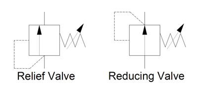
Pressure reducing valve symbols look very similar to those for pressure relief valves. This is because the valves work in similar ways except that the pressure sense line feeds from downstream of the reducing valve instead of upstream as in the relief valve. This means that the reducing valve controls the downstream pressure rather than the upstream pressure. As such the reducing valve cannot generate a downstream pressure that is not there but it can limit its value. Not how the arrow is shown in the middle positions indicating that it is normally open but closes the flow off when the pressure feed forces the arrow against the adjustable spring.
The middle symbol has a third tank line port and arrowheads pointing in both directions. In this valve, if the pressure downstream rises above the reducing valve"s setting then the valve will vent this pressure down the third line to provide a constant pressure in the sensed port.

A hydraulic circuit represents all the hydraulic components in a system. This includes the arrangement of the components and the behavior of the system as a whole in a universally accepted symbolic manner. In this article we will discuss the most common hydraulic symbols as represented in ISO 1219-1:2012. Armed with knowledge of how basic hydraulic components are represented in the hydraulic circuit; one can understand a wide range of different hydraulic symbols, representing components performing similar tasks with minor modifications.
A hydraulic reservoir stores hydraulic fluid. This is a must-have component in any hydraulic system. All hydraulic reservoirs are open to the atmosphere except in the case of those used in aircraft and submarines.
A hydraulic pump converts electrical and/or mechanical energy into hydraulic energy. The lower end (suction side) of a pump is connected to the hydraulic reservoir, the upper end is connected to the remaining circuit. The dark upper triangle in these hydraulic symbols indicates fluid going out of the system and hence represents a pump.
In the case of the hydraulic motor, the dark triangle is inverted indicating that the fluid is entering into the system. A hydraulic motor converts hydraulic energy into mechanical energy.
System output is represented by an arrow at 450 – this can be adjusted, In other words, that the pump/motor can deal with variable flow rate per shaft rotation. Most industrial applications use electric motors as prime movers to rotate hydraulic pumps. The electric motor is represented by the letter M inside of a circle. The curved arrow represents the direction of shaft rotation.
A pressure relief valve is a NC (normally closed) type safety valve which operates when system pressure increases above a maximum working pressure. The normally closed position is indicated by the arrow away from the center line. The dashed line indicates that the system pressure acts against spring force for valve actuation.
A direction control valve is a vital component in a hydraulic system. It controls the actuator’s position and direction by controlling the fluid flow into the actuator. Therefore direction control valves can be designated by number of ports and number of positions and are selected based on the application.
The central position is a neutral position and various neutral positions are available depending upon the application. All ports closed will increase the system pressure to the maximum – actuating the pressure relief valve. Whereas all ports connected in the neutral position will relieve the system by diverting fluid from the pump to the tank directly.
DCV can be distinguished depending upon the type of actuation. Hand levers, mechanical systems or solenoids are used to change the valve’s position. A spring is used to return to a neutral position.
The flow control valve is used to control the flow rate as well as the speed of the actuator. The position of flow control valve will lead to varied system behavior – an arrow representing the adjustable flow control.
A pressure indictaor is used to measure hydraulic pressure at any one point. Hence it is generally connected between the hydraulic pump and direction control valve
First of all you can see the electric motor driving the fixed delivery hydraulic pump in the above circuit. A safe pressure level is maintained using the pressure relief valve which is connected after the pump.
4/3 Direction control valve is being actuated by a solenoid control with all the ports are closed during the neutral position. In the figure, the DCV is in its 1st position and hence pressurized liquid will flow towards the right side of actuator. The left side of the actuator is connected to a reservoir meaning the actuator will move towards the left side.
Hydraulic circuits can be comprised of an infinite combination of cylinders, motors, valves, pumps and other equipment connected via hydraulic pipes and tubes. The complexity of these components are difficult to represent fully, so a family of graphic symbols have been developed to represent fluid power components and systems on schematic drawings.
The symbols do not identify component size or their actual position on the machine, however the symbols do provide vital information relating to the configurations and flow path connections.
Below we have summarised some of the most common symbols you may come across. Our technical sales engineers will be happy to help should you need any further help and assistance. Please get in touch on +44 (0)845-644-3640.
Pressure reducing valve is normally open valve and it allows the pressurised fluid to flow but when the pressure at the output of the valve is more than the valve pressure setti…

Below are some common illustrations of equipment located on fluids circuit diagrams, followed by descriptions of the most common elements. Later in this article series we will describe some simple hydraulic and pneumatic circuits composed of these circuit elements.
Needle valves are used to throttle or shut-off flow of fluids. They usually will vary flow with pressure or viscosity change. Some valves can be pressure and/or temperature compensating.
Flow control valves are used to control oil flow in one direction and unrestricted in the opposite direction. "Metered in" control means that the flow controls are controlling the fluid into the actuator, "metered out" is controlling the fluid out of the actuator. Some valves can be pressure and/or temperature compensating.
When the pilot line to a pilot-operated check valve is not pressurized, flow is allowed in one direction but blocked in the opposite direction. When the pilot line in a pilot-to-open valve is pressurized, the check valve is open, allowing flow in either direction.
When the pilot line to a pilot-operated check valve is not pressurized, flow is allowed in one direction but blocked in the opposite direction. When the pilot line in a pilot-to-close valve is pressurized, the check valve is closed, blocking flow in both directions.
Counterbalance valves are used to control overrunning loads and to support loads should a function be stopped at any point throughout its travel. NOTE: this valve is typically preset and should not be tampered with.
Flow fuses are normally open valves which close if the pressure difference between the inlet and outlet valves is too high compared to the design setting. The valve can be reset by reversing the direction of flow. When placed inline with an actuator (for example, a cylinder), flow fuses limit the maximum speed of that actuator.
Directional control valves are used to direct fluid flow into the appropriate lines for the designated operation. These valves are usually electrically controlled.
Hydraulic pumps are used to pump oil from the power unit to other parts of the hydraulic system. Some pumps have control options such as pressure or flow compensators.
Water modulating valves are used for controlling the oil temperature in the reservoir automatically by controlling the volume of water going through the heat exchanger.
Heat exchangers are used to remove heat from the circulating oil in the hydraulic system. The most common heat exchanger is water-to-oil but some times air-to-oil units are used. Coolers will cool the fluid.
Proportional valves are electrically controlled hydraulic valves. These valves proportionally control the hydraulic pressure and/or flow based on an electrical input signal.
For more information about reading hydraulic and pneumatic circuit diagrams, read the next article in this series which describes sample hydraulic circuits, or contact your Valmet representative.
Hydraulics engineers regularly encounter these diagrams, but these symbols can be daunting to interpret if you have limited experience with schematics and the fluid power industry.
On this page, Carr Lane ROEMHELD provides a comprehensive table outlining the definitions of each symbol used in a hydraulic diagram. Engineers can use this page as a reference to determine common schematic symbols used in fluid power, hydraulics, pneumatics, diagrams and circuits.

In this article, you are going to learn about different types of valve symbols used in P&ID. Many types of valves are used in process piping, and each has a different symbol. This makes the valve one of the tricky parts of reading P&ID. But with practice, you can easily remember these symbols and can read P&ID effectively.
There are two types of valve symbols — first, generic symbols, and second, a symbol with a modifier. Generic symbols will tell you that there is a valve in the line, but they will not tell you about the types of the valve. Whereas the valve symbol with modifier will tell you the type of valve used in the pipeline.
Here in the image above, you can see commonly used symbols for valves. These symbols are generic in nature — for example, the first symbol of a valve.
Now when you look at the symbol on the drawing, it just gives you an indication that some kind of valve is used, but it will not provide you with information about the type of valve, whether it is a gate, globe, or plug type valve. There are dedicated symbols for a gate, globe, plug, and ball valves which I will explain to you in minutes.
Similarly, the next two symbols are for three-way and four-way valves. It can be a plug or ball valve. The subsequent two symbols are a check valve and a stop check valve. These check valves can be swing check or lift check valves.
The next symbol is the excess flow valve. You can see that it is the same as a check valve the only difference is the written text below the valve symbol. You must be very careful while reading this type of symbol as it can easily be overlooked.
The last symbol is of automatic recirculation valve. This type of valve is used in the pump discharge line to ensure the pump will not suffer from low inlet pressure, which leads to cavitation.
Here in the image above, the first symbol is of angle valve. In most cases, a globe valve is used as an angle valve. The next symbol is the relief valve used to protect the piping system or equipment from overpressure.
Now the breather valve is used on the cone roof tank. This valve serves the function of the relief valve and vacuum valve. In the event of over-pressure, this valve release the pressure, and in case a vacuum is created in the tank, this valve allows air to enter the tank. Just like breathing air in and out.
The vacuum valve prevents damage to the equipment from negative pressure. Pilot-operated relief valves are just working as relief valves but are used for large-size piping. This type uses a small relief valve to operate the main relief valve. This arrangement is cost-effective in large-size relief operations.
In the image above, you can see the gate valve. Now see the P&ID symbol for the gate valve. It is a modification of a generic valve symbol by inserting a vertical line between two triangles. Three symbols shown below are the gate valve symbols used in isometric drawings. The first is for butt-welding ends, the second is for flanged end valve, and the third is for socket end connection.
For a globe valve, a symbol is modified by adding a small dark circle between triangles. You can see that P&ID and isometric symbols are almost the same, with the only change in end types.
You can see that there are two P&ID symbols for a ball valve. The reason is that P&ID and isometric drawing symbols are changed from company to company. So if you switch the company, you should be aware of this. Similarly, you can see the ISO symbols for butt, flanged, and socket ends ball valve.
Same as a ball valve, a needle valve also has multiple P&ID symbols. If you can see that even though these symbols are different, you can still easily interpret them. If you are using second P&ID symbols, your isometric symbol will be changed accordingly.
For the plug valve, the first symbol is a bit confusing with a globe valve. If you remember the symbol of a globe valve, it has a dark circle in between the triangle, whereas here, only the circle outline is there. So when you see this type of symbol, better to double-check the drawing.
The butterfly valve symbol is the only symbol where a full triangle is not used. If you refer to the first symbol, it is similar to a globe valve, but a triangle is not full. The alternative symbol is clearer in this case. For isometric symbols, you can see that there is no socket end butterfly valve.
Here is the diaphragm valve. There is no butt-welded diaphragm valve available. Most diaphragm valves are flange type, and they are used to handle process media with solid particles.
You can see the symbols in the image above with a special note. The first symbol is a special valve. The word NC return below the second symbol is more important. It indicates that this valve remains closed during normal operation. Now the next two symbols are also used alternatively to show the valve position during normal operation.

Out of any topic under the patio-sized umbrella of fluid power, hydraulic symbology garners the most requests from those wishing to learn more about fluid power. Reading any schematic with more than three symbols can be daunting if your experience is limited. But it’s not impossible to learn. In fact, it only takes a basic level understanding of how symbols work and how they’re arranged in a diagram. One challenge – even if you’ve memorized every symbol in the library – is understanding why a particular symbol is used in a circuit; that part is hard to teach and just comes with experience.
The third most common line you will see is the simple dashed line. This is a dual function line, representing both pilot and drain lines. A pilot line in both representation and function uses hydraulic energy to signal or operate other valves. Learning to comprehend pilot lines is key to understanding advance hydraulic schematics. As a drain line, the dashed line simply represents any component with leakage fluid needing a path represented in the drawing.
If we get slightly more advanced than your basic line, we have three other common shapes used in hydraulic schematics. These are the circle, square and diamond. Ninety nine percent of hydraulic symbols use one of these three as a foundation. Pumps and motors of every kind are drawn using a circle, as are measuring instruments. Valves of every kind use the basic square as a start. Some are simply one square, such as pressure valves, but others use three joined squares, such as with a three-position valve. Diamonds are used to represent fluid conditioning devices, like filters and heat exchangers.
Let’s assume the relief valve is set to 2,000 psi. You’ll have noticed the dashed line coming from the bottom of the symbol, rounding the corner and is attached to the left side. This dashed line indicates the valve is directly operated by the pressure at its inlet port, and that pilot fluid can affect the valve by pushing the arrow to the right. The actual valve has no arrow, of course, but as is the nature of hydraulic symbols, just represents a visual model of what occurs. As pressure in the pilot line approaches 2,000 psi, the arrow is pushed until the valve reaches the centre, allowing fluid to pass, which in turn reduces pressure until upstream is 2,000 psi.
The pressure reducing valve is the only normally open pressure valve in hydraulics. As you can see, it’s very similar to the relief valve, save two changes in the symbol. Firstly, the arrow shows it flows in its neutral position, whereas the relief valve is blocked. Secondly, it gets its pilot signal from downstream of the valve. When downstream pressure rises above the spring setting value, the valve closes, preventing incoming pressure from reaching the downstream path, which allows pressure to decay back to below the pressure setting.
The basics of hydraulic symbology are quite easy, but I’ve only scratched the surface. There are many specialized symbols representing things like electronics, accumulators, various cylinders and ball valves, which I don’t have the room to show. Furthermore, each symbol I’ve shown represents a small portion of the modifications possible to each; there is probably a hundred or more ways to represent a hydraulic pump with a schematic symbol.
Finally, the way in which hydraulic symbols are combined to create a complete schematic representing an actual machine is endless. I recommend you spend time reading hydraulic schematics to interpret the symbols, whenever you have time. Not only will you discover unique symbols, but you’ll come across unique ways to use old symbols and components in a hydraulic circuit.
NG6 / Cetop-3 / D03 Modular Stack Pressure Relief Valve. | SEVEN OCEAN HYDRAULICS - A world-class manufacturer of high performance hydraulic valves, power units and accessories.
Located in Taiwan since 1989, SEVEN OCEAN HYDRAULIC INDUSTRIAL CO., LTD. has been a hydraulic valves, power units and accessories manufacturer. Their main products, include Modular Check Valve, Solenoid Operated Directional Control Valves, Pilot Operated Directional Control Valves, 4/2 Directional Control Valves, 4/3 Directional Control Valves, Variable Volume Vane Motor Pumps, Modular Stack Valves, Sandwich Valves, Hydraulic Power Units, Hydraulic Pressure Control Valves and Flow Control Valves, which are suitable for forklift, machine tool, plastic injection and recycling electrical machinery industries .
SEVEN OCEAN HYDRAULICS"s Modular Check Valve are reliable, sustainable, and cost effective, bringing you long-term value at an affordable price-point. With over 31 years of experience in manufacturing hydraulic systems, valves and components, Seven Ocean Hydraulics is able to streamline production time and has a greater control over product quality with in-house manufacturing of core components. We have gained trust from world- renowned brands for OEM projects, providing essential components for hydraulic products that are seen and used all over the world.
SEVEN OCEAN HYDRAULICS has been offering customers high-quality hydraulic valves, both with advanced technology and 31 years of experience, SEVEN OCEAN HYDRAULICS ensures each customer"s demands are met.


 8613371530291