
hydraulic safety valve symbol made in china

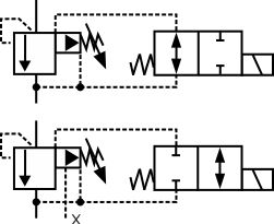
A tiny detail of the hydraulic check valve symbol direction is wrong, which put the hydraulic check valve manufacturer in a very difficult position, the factory is almost closed. There is a devil in the details. Whether you can grasp the devil of the hydraulic check valve symbol requires you to think every day, in addition to hydraulic check valve, hydraulic check valve, and still hydraulic check valve.
When I opened the mailbox, I saw the e-mail of Adair who we had known for 3 years. There was a habit with Adair. He purchases only one type of hydraulic valves from each one hydraulic valve manufacturer. We AAK HYDRAULIC VALVE has been his supplier for the hydraulic pressure valves. After reading the email, it was actually a proofing request for a hydraulic check valve, not a hydraulic pressure valve. It was a little abnormal. I thought he sent the wrong email.
I reminded him whether the e-mail was sent by mistake. He said bluntly that he would need 3 samples of the hydraulic check valve as soon as possible, according to the drawings in his email. Somehow, I always felt there was a problem somewhere, and I went to see the drawing of the hydraulic check valve. It is found that in the layout at the bottom of the drawing, the arrow direction on the hydraulic check valve symbol is reversed. For the hydraulic check valve symbol, the arrow direction is reversed, which is fatal. It seems that a designer is unlikely to make such a low-level mistake.
When the technical team got the drawing and started proofing, they called me. The hydraulic check valve symbol on the drawing seemed wrong. I"m glad they can also find that there is an objection to the hydraulic check valve symbol. I asked what they think of the hydraulic check valve symbol. They s ested making two sets of samples, one according to the hydraulic check valve symbol on the customer"s drawing, and the other is for the hydraulic check valve symbol we understand.
When Adair received two sets of samples, he deliberately asked why they were two sets of samples. When we pointed out the details of the hydraulic check valve symbol, Adair began to tell me the devil"s story of the hydraulic check valve symbol.
6 months ago, he sent his hydraulic valve manufacturer the drawing with this hydraulic check valve symbol, which was made by their chief designer overnight. The hydraulic valve manufacturer proofed according to this drawing. As a result, the hydraulic check valve sample was also approved at one time. The devil began to make trouble from this time. The 2,000 hydraulic check valves were produced and shipped to his customer. The customer is testing a new production line and needs to use these hydraulic check valves. After installation, there is a big problem in startup and commissioning. Because of the wrong direction, the medium returned, polluting the whole new production line, and directly causing a loss of more than 260,000 US dollars. The customer sent the loss list to his boss, who asked the hydraulic valve manufacturer to bear it.
The hydraulic valve manufacturer quickly found out the reason, but did not dare to directly tell the boss that this is the problem that the hydraulic check valve symbol on your drawings is wrongly marked. If offended the designer, there will be even no opportunity to quote in the future. Now the hydraulic valve manufacturer is in a dilemma. Bear the loss, the number is large. Not to bear the loss, they only have this only customer, Adair’s company.
Who would have thought that this hydraulic check valve symbol butterfly wings directly incited the loss of more than 260,000 US dollars across the Atlantic. When the devil comes out, it seems difficult to find a way to the best of both worlds. The only way is to keep the devil in a bottle.
AAK knows that there is a devil when looking at the hydraulic check valve symbol. If there is any problem with the hydraulic check valve symbol, please contact AAK HYDRAULIC VALVE: www.aakindustry.com
We promise to treat every new product with the attitude of "doing things seriously" and "sincerely treating people". We will continue to open up the market with high-quality, cost-effective Alu bronze Gate Valve, Check Valve Home Depot, GOST Globe Valve, paving the way for your success. We will win your trust and support in us with reliable product quality, preferential product prices, perfect after-sales service, and good business reputation. In terms of attitude, we insist on doing only one thing, which is to achieve the ultimate quality of our products. With the concept of "Customer First", we wholeheartedly provide our customers with high-quality products and efficient services. Relying on the management policy of "ruling the enterprise by virtue and putting people first", we have widely absorbed elites from all walks of life. Our company implements market-oriented, information development, talent development, scientific and technological development, and pursues higher enterprise value and higher social effect. What needs to be understood is the customer, and what needs to be improved is yourself.
swing flap check valve Packaging & Shipping Shipping:20 days after order confirmed. Packaging:Plywood case. Our Services 1.Good quality and low price. 2.We can provide free sample,but you will bear the courier charge. 3.Good after-sale service. About us 1.We have...
DIN3202 brass seal double flange no return valve Description: Nominal diameter: DN50–DN400 Working pressure: PN10/16; Valve Design: BS5153,API594 Face-to-face: DIN 3202 F6,ASME B16.10; No Noise Ductile Iron Swing Check Valve Rubber Seal Blue Color For Water Standard: EN1092-2...
hydraulic non return valve symbol Detailed introduction of HC41T silencing check valve (copper) The HC41T silencing check valve (copper) overview: The HC41T silencing check valve (copper) produced by our factory is suitable for the water supply and drainage pipes. The valve...
Check Valve For Sea Water Product Description Flange Swing Check Valve Technical Specifications: 1. Flange end, according to ANSI BS DIN JIS etc. 2. Face to Face: MSS SP-71 DIN3202 F1 , BS4090 /BS5153 3. End Flange: DIN 2543-2545/DIN 2501 4. Inspection and Test: DIN 3230...
Cast Steel Swing Check Valve Swing Check Valves : API 6D, BS 1868, BS 1873, ASME B16.34, Bolted Bonnet, Pressure Seal, Bolted Cover, BW, Flanged Ends, Class 150 - 2500, 2 -36 Inch. Valve Type: Cast Steel Swing Check Valve. Valve Size: 2 ”- 36”. Pressure Rating: Class 150 –...
Micro resistance counter weight soft close check valve Brief introduction: This counter weight nozzle buffer swing check valve is a valve which is automatically opened and closed by the flow of the medium itself and used to prevent the reverse flow of the medium,and eliminate...
SS316 Check Valve Function: Ddcv Double Lobe, Nrvr Silence, Sfcv Rubber Lobe, Nrvz Silence, Nrvg Silence Sealing Form: Metal Flow Direction: Unidirection Standard: DIN Application: Industrial Usage, Water Industrial Usage Body Material: Carbon Steel/Stainless Steel Bonnet...
Wafer Double Disc Swing Check Valve Model No.: H76X China Double Disc Wafer Swing Check Valve manufacturer KEMUS offers Wafer Swing Double Disc Check Valves in Cast Iron & Cast Steel, DN50-DN1000. With short shutoff stroke and spring loaded, wafer double disc swing check...
non return valve symbol flow direction Product Description DIN PN10 GG25 Non Return Check Valve Our services About Sample We can provide the free sample, but you have to bear the delivery costs. About Package We can make the form of the package and transportation according to...
swing flap check valve Swing Check Valve (BS5153) Confirm to BS5153 PN16 Flange Drilled Conforms to BS4504 Face to face Dimensions Conform to Series 2 of BS5153 We company have other valves: gate valve, check valve, ball valve, butterfly valve, safety valve, globe valve, plug...
We adhere to the concept of high quality, high requirements and high performance, and provide reliable Non-rising Stem Globe Valve, KSB High Pressure Globe Valve, Pneumatic Butterfly Valve Wafer Type and services to users. We"re well-known as one of the leading Hydraulic Non Return Valve Symbol manufacturers and suppliers in China for our quality products and good service. Please feel free to buy Hydraulic Non Return Valve Symbol made in China here from our factory.
Alibaba.com offers 173,284 hydraulic valve china products. such as new, used. You can also choose from flow control valve, directional control valve, and pressure control valve. As well as from 1 year, 6 months, and 1.5 years. And whether hydraulic valve china is valves, hydraulic power units, or fittings.
Certification: TS licensing A1, A2, B1, B2, API-6D, CE, ISO9001, ISO14001, OHSAS18001, TUV issued by the API 6FA gate valve, API607 ball valve fireproof test
Neway Valve is one of the leading manufacturers of butterfly valves in China. It has a world-class valve plant that covers an extensive valve program to meet the needs of clients.
Neway butterfly valves are available in a number of series including T Series for concentric butterfly valves, TB Series for double offset butterfly valves, and TC Series for triple offset butterfly valves. These valves are used largely in chemical, nuclear, offshore, power, oil and gas, mining, and air separation industry.
Chaoda Group Wenzhou E-business Co., Ltd is an entirely owned branch of the Chaoda Valves Group Co., Ltd to market and sell valves, forging, casting, flanging, gas meter, etc. The company has earned special titles such as “Zhejiang Famous Product,” “Zhejiang Famous Brand,” and “Zhejiang Exporting Famous Brand.”
Chaoda houses a variety of cryogenic valves that are suitable for many different industries. They feature cryogenic globe, butterfly, check, trunnion ball, floating ball, check, gate, and other valves.
Chaoda forged steel cryogenic lift check valve is immersed in liquid nitrogen (-196 degree C) for 2 to 6 hours, then returned to normal temperature during production. This cycle is repeated twice to ensure the valve’s cryogenic abilities are top-notch. The valve can be made of carbon steel, stainless steel, alloy steel, and duplex stainless steel. It can be operated manually, by gear, electrically, or pneumatically. The valve can be used with oil, chemicals, natural gas, petrochemicals, coal chemicals, and more.
Beijing Valve General Factory Co., Ltd, or BVMC,was founded in 1953. With more than six decades of experience in the industry, the company has earned the position of vice chairman of National Valve Industry Association.
Beijing Valve General Factory has more than 60 years of experience in valve design and manufacturing. The company is actively involved in many national projects and also exports valves to more than 70 countries and regions around the world.
Their cryogenic ball valve can be used in temperatures ranging from -196 to 121 degrees C. The valve can be used with LNG and liquid nitrogen and is fire-safe and anti-static. The valve stem is extended and has extra packing ensuring any anti-flow. You can operate the valve with a handwheel, worm wheel, electric actuator or pneumatic actuator.

A hydraulic circuit represents all the hydraulic components in a system. This includes the arrangement of the components and the behavior of the system as a whole in a universally accepted symbolic manner. In this article we will discuss the most common hydraulic symbols as represented in ISO 1219-1:2012. Armed with knowledge of how basic hydraulic components are represented in the hydraulic circuit; one can understand a wide range of different hydraulic symbols, representing components performing similar tasks with minor modifications.
A hydraulic reservoir stores hydraulic fluid. This is a must-have component in any hydraulic system. All hydraulic reservoirs are open to the atmosphere except in the case of those used in aircraft and submarines.
A hydraulic pump converts electrical and/or mechanical energy into hydraulic energy. The lower end (suction side) of a pump is connected to the hydraulic reservoir, the upper end is connected to the remaining circuit. The dark upper triangle in these hydraulic symbols indicates fluid going out of the system and hence represents a pump.
In the case of the hydraulic motor, the dark triangle is inverted indicating that the fluid is entering into the system. A hydraulic motor converts hydraulic energy into mechanical energy.
System output is represented by an arrow at 450 – this can be adjusted, In other words, that the pump/motor can deal with variable flow rate per shaft rotation. Most industrial applications use electric motors as prime movers to rotate hydraulic pumps. The electric motor is represented by the letter M inside of a circle. The curved arrow represents the direction of shaft rotation.
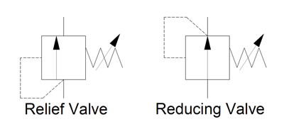
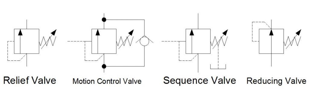
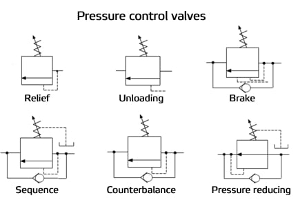
A pressure relief valve is a NC (normally closed) type safety valve which operates when system pressure increases above a maximum working pressure. The normally closed position is indicated by the arrow away from the center line. The dashed line indicates that the system pressure acts against spring force for valve actuation.
A direction control valve is a vital component in a hydraulic system. It controls the actuator’s position and direction by controlling the fluid flow into the actuator. Therefore direction control valves can be designated by number of ports and number of positions and are selected based on the application.
The central position is a neutral position and various neutral positions are available depending upon the application. All ports closed will increase the system pressure to the maximum – actuating the pressure relief valve. Whereas all ports connected in the neutral position will relieve the system by diverting fluid from the pump to the tank directly.
DCV can be distinguished depending upon the type of actuation. Hand levers, mechanical systems or solenoids are used to change the valve’s position. A spring is used to return to a neutral position.
The flow control valve is used to control the flow rate as well as the speed of the actuator. The position of flow control valve will lead to varied system behavior – an arrow representing the adjustable flow control.
A pressure indictaor is used to measure hydraulic pressure at any one point. Hence it is generally connected between the hydraulic pump and direction control valve
First of all you can see the electric motor driving the fixed delivery hydraulic pump in the above circuit. A safe pressure level is maintained using the pressure relief valve which is connected after the pump.
4/3 Direction control valve is being actuated by a solenoid control with all the ports are closed during the neutral position. In the figure, the DCV is in its 1st position and hence pressurized liquid will flow towards the right side of actuator. The left side of the actuator is connected to a reservoir meaning the actuator will move towards the left side.

Out of any topic under the patio-sized umbrella of fluid power, hydraulic symbology garners the most requests from those wishing to learn more about fluid power. Reading any schematic with more than three symbols can be daunting if your experience is limited. But it’s not impossible to learn. In fact, it only takes a basic level understanding of how symbols work and how they’re arranged in a diagram. One challenge – even if you’ve memorized every symbol in the library – is understanding why a particular symbol is used in a circuit; that part is hard to teach and just comes with experience.
The third most common line you will see is the simple dashed line. This is a dual function line, representing both pilot and drain lines. A pilot line in both representation and function uses hydraulic energy to signal or operate other valves. Learning to comprehend pilot lines is key to understanding advance hydraulic schematics. As a drain line, the dashed line simply represents any component with leakage fluid needing a path represented in the drawing.
If we get slightly more advanced than your basic line, we have three other common shapes used in hydraulic schematics. These are the circle, square and diamond. Ninety nine percent of hydraulic symbols use one of these three as a foundation. Pumps and motors of every kind are drawn using a circle, as are measuring instruments. Valves of every kind use the basic square as a start. Some are simply one square, such as pressure valves, but others use three joined squares, such as with a three-position valve. Diamonds are used to represent fluid conditioning devices, like filters and heat exchangers.
Let’s assume the relief valve is set to 2,000 psi. You’ll have noticed the dashed line coming from the bottom of the symbol, rounding the corner and is attached to the left side. This dashed line indicates the valve is directly operated by the pressure at its inlet port, and that pilot fluid can affect the valve by pushing the arrow to the right. The actual valve has no arrow, of course, but as is the nature of hydraulic symbols, just represents a visual model of what occurs. As pressure in the pilot line approaches 2,000 psi, the arrow is pushed until the valve reaches the centre, allowing fluid to pass, which in turn reduces pressure until upstream is 2,000 psi.
The pressure reducing valve is the only normally open pressure valve in hydraulics. As you can see, it’s very similar to the relief valve, save two changes in the symbol. Firstly, the arrow shows it flows in its neutral position, whereas the relief valve is blocked. Secondly, it gets its pilot signal from downstream of the valve. When downstream pressure rises above the spring setting value, the valve closes, preventing incoming pressure from reaching the downstream path, which allows pressure to decay back to below the pressure setting.
The basics of hydraulic symbology are quite easy, but I’ve only scratched the surface. There are many specialized symbols representing things like electronics, accumulators, various cylinders and ball valves, which I don’t have the room to show. Furthermore, each symbol I’ve shown represents a small portion of the modifications possible to each; there is probably a hundred or more ways to represent a hydraulic pump with a schematic symbol.
Finally, the way in which hydraulic symbols are combined to create a complete schematic representing an actual machine is endless. I recommend you spend time reading hydraulic schematics to interpret the symbols, whenever you have time. Not only will you discover unique symbols, but you’ll come across unique ways to use old symbols and components in a hydraulic circuit.

Below are some common illustrations of equipment located on fluids circuit diagrams, followed by descriptions of the most common elements. Later in this article series we will describe some simple hydraulic and pneumatic circuits composed of these circuit elements.
Needle valves are used to throttle or shut-off flow of fluids. They usually will vary flow with pressure or viscosity change. Some valves can be pressure and/or temperature compensating.
Flow control valves are used to control oil flow in one direction and unrestricted in the opposite direction. "Metered in" control means that the flow controls are controlling the fluid into the actuator, "metered out" is controlling the fluid out of the actuator. Some valves can be pressure and/or temperature compensating.
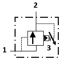
When the pilot line to a pilot-operated check valve is not pressurized, flow is allowed in one direction but blocked in the opposite direction. When the pilot line in a pilot-to-open valve is pressurized, the check valve is open, allowing flow in either direction.
When the pilot line to a pilot-operated check valve is not pressurized, flow is allowed in one direction but blocked in the opposite direction. When the pilot line in a pilot-to-close valve is pressurized, the check valve is closed, blocking flow in both directions.
Counterbalance valves are used to control overrunning loads and to support loads should a function be stopped at any point throughout its travel. NOTE: this valve is typically preset and should not be tampered with.
Flow fuses are normally open valves which close if the pressure difference between the inlet and outlet valves is too high compared to the design setting. The valve can be reset by reversing the direction of flow. When placed inline with an actuator (for example, a cylinder), flow fuses limit the maximum speed of that actuator.
Directional control valves are used to direct fluid flow into the appropriate lines for the designated operation. These valves are usually electrically controlled.
Hydraulic pumps are used to pump oil from the power unit to other parts of the hydraulic system. Some pumps have control options such as pressure or flow compensators.
Water modulating valves are used for controlling the oil temperature in the reservoir automatically by controlling the volume of water going through the heat exchanger.
Heat exchangers are used to remove heat from the circulating oil in the hydraulic system. The most common heat exchanger is water-to-oil but some times air-to-oil units are used. Coolers will cool the fluid.
Proportional valves are electrically controlled hydraulic valves. These valves proportionally control the hydraulic pressure and/or flow based on an electrical input signal.
For more information about reading hydraulic and pneumatic circuit diagrams, read the next article in this series which describes sample hydraulic circuits, or contact your Valmet representative.
In line check valve is belong to one type of the shut-off valves, it is designed with a one piece body and all steel construction, both inlet and outlet ports are female fitting.
A in-line check valve consists of a housing with an integrated valve seat, a tempered and ground closing element (cone) and a pressure spring. Jiayuan manufactures and supplies inline check valves, can meet the needs of clients across a vast range of industries.
These are in-line unidirectional valves with standard spring crack pressures. When the pressure is below the cracking pressure, the spring will close the valve to prevent back-flow in the process.
Throttle globe valves use a linear motion to move a closure into and out of the valve seat, with the valve body being a spherical chamber. They are designed to control process flow, pressure, or temperature when combined with an actuator assembly. A cage or retainer-style design is used in many single-seat bodies to hold the seat seal, provide plug guiding, and give a method for determining the flow characteristics of a specific valve. Single-seat globe valve bodies with cage or retainer structure may also easily adjust flow characteristics by changing the trim, enabling decreased capacity flow, noise reduction, or decreasing or eliminating cavitation.
Globe valves provide users exceptional performance and reliability and come in a range of sizes from DN15 to DN900. They can assist in meeting a variety of application demands, from general to severe, small size to big size, hot temperature to cold temperature.
Different kinds of bonnets are offered to handle various application temperatures. To protect packing materials when the valve is used in highly hot or cold situations, this principally includes basic bonnets and optional extension bonnets.
Boiler and main steam vents and drains, fuel oil systems, feedwater or chemical feed systems, turbine lubrication oil systems, and cooling water systems are just a few of the many places where globe valves are used.
Globe valves can be equipped with either balanced or unbalanced valve plugs. Balanced plugs permit equal process pressure above and below the valve plug, with the normal flow down through the seat ring. Unbalanced valve plugs are solid with no through the hole, and flow is typically upward via the seat ring.
There are various ways to guide the plug in globe valves, the most popular of which are cage guided and post-guided. Cage-guided assemblies come in both balanced and unbalanced plug configurations. This method of guiding employs the outside diameter of the plug to touch the inside diameter of the cage, which provides excellent plug stability and alignment but necessitates extremely tight tolerances between the plug and cage. The seat retainer is used in place of the retainer in the post-guided assembly. The seat retainer has a guide cage that guides the post on the plug. Because this method provides for an unobstructed flow route around the plug, the back-guided trim is better appropriate for viscous and unclean fluids.
Globe valves can be linear, equal percentage, or quick opening and can satisfy capacity demands from 0.001 Cv up to 12,000 Cv through a variety of trims with various flow characteristics.
Globe valves are often used in control and isolation systems. This motion is straightforwardly linear. Since this is the case, it can quickly allow or restrict fluid flow. It makes for a secure seal. This is why globe valves are commonly utilized in the petroleum industry.
Globe and gate valves are the most common types of valves in the industry, each having its own unique functions and design features. Below, we highlight the key distinctions between globe valves and gate valves:
For newbies, the gate valve may be very similar to the globe valve. But if you take close look at these two different valves, you will find the gate valve is much simple, a gate/disc you can see at the top of the valve body. When the gate valve is opened, the gate/disc will upward action, and complete on the top part of the bonnet, and the body becomes hollow.
But for the globe valve, the plug and seat are complete inners of the valve body. The design permits impediments that help the globe valve in its primary function of throttling and providing positive shut-off. Additionally, the design allows for variations in flow rate and direction, which can lead to a high-pressure drop.
When compared to a gate valve, a globe valve cannot close tightly. Pipeline gate valves provide a tight shut-off feature. Gate valves are utilized upstream of globe valves due to their tight shut-off abilities. This gate and globe valve combination may have been visible at the discharge pipe of a pump.
A globe valve needs more torque to operate. This higher power consumption for globe valves is also taken into account when constructing automated and motorized valve actuators.
When gate valves are used to regulate flow, we witness noise, vibration, and seat/disk damage, so gate valves were not designed to regulate flow. In the event that a gate valve is unavailable, a globe valve might be utilized to stop and start the flow. Generally speaking, a gate valve is only utilized for isolating fluid. As designs exist for both directions of flow, a gate valve can be utilized in either direction.
Globe valves can be maintained in place, while almost all gate valves need to be removed from the piping system in order to make repairs for leakage problems.
A gate valve will bind and be impossible to open against a large differential pressure, while a globe valve can. The seat will score and leak if you attempt to open against high differential pressure.
The gate valve is perfect for uses where low-pressure losses are essential. It is a multidirectional valve. The globe works best in settings where large pressure variations are not a concern. Globe valve only has one direction, and you will see an arrow mark on the body to show the flow direction.
Gate valves are linear valves that belong to the family of shutoff valves. The gate valve is widely used to isolate media because its wedge-shaped disc can effectively shut off fluid. This type of valve is suitable for applications requiring a tight seal. For thicker and more viscous fluids, the knife gate valve is the best choice.
Since there is no blockage in the media flow path, gate valves only cause minor pressure drops. The valve opens by the upward movement of the gate disc. It closes by lowering the disc to connect with the seats. The disc of a gate valve can be shaped as a wedge, a knife, or a parallel plane.
The gate valve is not utilized to control the flow of media, although having considerable throttling capacity. Due to the thinness of its disc, it might get misaligned from its seat as a result of media vibration. Its service life is shortened and harm is caused by this situation. The gate valve should completely open or fully close when in operation to increase the lifespan of the valve.
Here is what makes a globe valve different from a ball valve:Globe ValveBall ValveBest suited for controlling, opening, and closing flowsExcellent for opening and closing services
Globe valves are control valves that are used to control, start, and stop the flow of media through a pipe. They feature a spherical body shape the appearance; on the inside, a plug fits on the end of a threaded rotating stem that is upward and downward to control media flow. Globe valves are a type of linear motion valve, which indicates that the valve mechanism moves in a straight line.
Gate valves are excellent for applications requiring tight shutoff or isolation. In the half-open state, gate valves cannot withstand a strong flow of media and are thus not utilized to regulate flow. They are utilized in industrial oil and gas pipe systems, water systems, and maritime sectors.
Throttle Trip Valves are a single, highly reliable valve assembly that can control flow and shut off in an emergency. The throttling valve controls the flow of steam and gas in large, high-pressure pipelines, like the main steam line for a high-pressure turbine or the gas supply line for a turboexpander. As trip valves, they add a crucial level of safety to these uses without the cost of a separate trip valve. When manually or automatically tripped, the valves quickly stop the flow of water to protect expensive equipment.
When the throttle trip valve is opened, the pressure on the main disc is released by a pilot valve inside the valve. The seal-welded seat ring fits tightly to the body and has an expansion groove to keep the seating face from distorting. Gaskets of the flexitallic type seal well at all cover joints. The yoke and latching assembly are made to be easy to adjust while it is in use. To save space and enable the use of smaller operators, venturi seats can be offered in high-pressure applications. For direct connections to steam turbines, valves can be made with either welded ends or ANSI flange connections.
A needle valve is used to precisely regulate the flow of clean gases or liquids. Smooth flow control is achieved by gradual changes to the stem and plunger. The needle valves often feature a small flow capacity and a large pressure drop. Standard needle valve port diameters range from DN2 to 12 mm(1/8″ to 2″). A needle valve’s most typical application is to regulate gas flow, such as propane in a tank. Need valve is a kind of globe valve.


 8613371530291