
hydraulic safety valve symbol pricelist
Inline Pressure Relief valves are commonly used to set the correct pressure on hydraulic systems. Pressure spikes will be safely bypassed back to tank allowing for both correct functioning of equipment & also for operator safety.
Good for protecting hydraulic motors on overrun in high momentum applications eg conveyors and spinning Wheels or blades. Oil Pressure relief is adjustable using Allan key or Knob.
IMPROPER SELECTION, INSTALLATION, IMPLEMENTATION AND/OR OPERATION BY ANYONE OTHER THAN PERSONS WITH APPROPRIATE TECHNICAL AND MECHANICAL TRAINING CAN RESULT IN DAMAGE TO EQUIPMENT OR PROPERTY, SERIOUS PERSONAL INJURY OR DEATH. PROPER PRECAUTIONS AND SAFETY PROCEDURES SHOULD BE IMPLEMENTED PRIOR TO INSTALLATION AND OPERATION OF EQUIPMENT.
![]()
Searching for tools to control the flow of your piping system? Explore one of the largest featured collections of products and discover a range of wholesale safety valve price list on Alibaba.com. When you search for safety valve price list and related items, you will be able to find many types of safety valve price list varying in size, shape, use, and quality, all at prices in which are highly reasonable!
There are many uses of valves - mainly controlling the flow of fluids and pressure. Some examples include regulating water for irrigation, industrial uses for controlling processes, and residential piping systems. Magnetic valves like those using the solenoid, are often used in a range of industrial processes. Whereas backflow preventers are often used in residential and commercial buildings to ensure the safety and hygiene of the water supplies. Whether you are designing a regulation system for irrigation or merely looking for a new replacement, you will be able to find whatever type of safety valve price list that you need. Our products vary from check valves to pressure reducing valves, ball valves, butterfly valves, thermostatic mixing valves, and a lot more.
![]()
Searching for tools to control the flow of your piping system? Explore one of the largest featured collections of products and discover a range of wholesale pressure relief valve price list on Alibaba.com. When you search for pressure relief valve price list and related items, you will be able to find many types of pressure relief valve price list varying in size, shape, use, and quality, all at prices in which are highly reasonable!
There are many uses of valves - mainly controlling the flow of fluids and pressure. Some examples include regulating water for irrigation, industrial uses for controlling processes, and residential piping systems. Magnetic valves like those using the solenoid, are often used in a range of industrial processes. Whereas backflow preventers are often used in residential and commercial buildings to ensure the safety and hygiene of the water supplies. Whether you are designing a regulation system for irrigation or merely looking for a new replacement, you will be able to find whatever type of pressure relief valve price list that you need. Our products vary from check valves to pressure reducing valves, ball valves, butterfly valves, thermostatic mixing valves, and a lot more.
![]()
The purpose of the valve is to, when energized, provide a flow path for a flow of hydraulic fluid from its source to the hydraulic system. When de-energized, the valve blocks flow from the hydraulic energy source and vents the hydraulic system to tank.
Q: What is Control Reliablitiy?A: Control Reliability essentially states that the safety system be designed, constructed and installed such that the failure of a single component within the device or system should not prevent normal machine stopping action from taking place, but shall prevent a successive machine cycle from being initiated until the failure is corrected. To achieve “Control Reliability”, a device should feature both redundancy and fault detection.
A: A safety valve, as it pertains to fluid power, is a component that, when properly applied, can allow access to an otherwise hazardous area. This is achieved by isolating the hydraulic source away from the system and venting any residual system pressure, downstream from the valve, to tank.
A: During normal operation, the valve operates like a traditional 3-way. If either of the redundant elements malfunction, the safety PLC or safety relay, monitoring the state of the redundant switches, will command the valve to its safe condition.
A: The three different configurations of Control Reliable Safety Valves are 2-way for blocking applications, 3-way for block and bleed applications, and LOTO or Lockout/Tagout.
A: A relief valve is a device that limits the maximum pressure in a system. It does help to keep a system and its surrounding environment safe from catastrophic failures due to over-pressurization but it is not a true safety product. The safety valves that we refer to are redundantly monitored devices that meet the rigorous requirements of safety standards organizations such as ANSI and ISO.
A: A blocking valve, as it pertains to fluid power, is a component that, when properly applied, can allow access to an otherwise hazardous area. This is achieved by isolating the hydraulic source away from the system.
A: During normal operation, the valve operates like a traditional 2-way. If either of the redundant elements malfunction, the safety PLC or safety relay monitoring the state of the redundant switches will command the valve to its safe condition.
Standard materialsinclude 316 stainless steel bodies and removable seat glands with 17-4PH stainless steel removable stem and stem seats. Standard O-ring material on the stem is Viton Valves may be used up to 400° F.
Inlet connections are for 9/16" O.D. tubing (HF9) with adapters for other sizes available. Outlet connections are 1/2" NPT. These valves are not recommended for use below 1,500 psi, and are not readily adjustable in the field without proper test equipment. Pressure settings are made at the factory and valves are tagged accordingly.
HiP relief valves are now available with CE marking. These products will proudly be marked with the CE symbol, signifying they comply with the stringent requirements of the Pressure Equipment Directive (PED). To order, add -CE to your relief valve part number.
Standard materials include 316 stainless steel bodies and removable seat glands with 17-4PH stem and seal ring. Standard O-ring material on the stem is Viton. The seat material is Peek. Valves may be used up to 400°F with standard Vtion O-ring or 450°F with the Kalrez O-ring option.
Inlet connections are for 9/16" O.D. tubing (HF9) with adapters for other sizes available. Outlet connections are 1/2" NPT. These valves are not recommended for use below 1,500 psi, and are not readily adjustable in the field without proper test equipment. Pressure settings are made at the factory and valves are tagged accordingly.
HiP relief valves are now available with CE marking. These products will proudly be marked with the CE symbol, signifying they comply with the stringent requirements of the Pressure Equipment Directive (PED). To order, add -CE to your relief valve part number.
HiP relief valves are now available with CE marking. These products will proudly be marked with the CE symbol, signifying they comply with the stringent requirements of the Pressure Equipment Directive (PED). To order, add -CE to your relief valve part number.

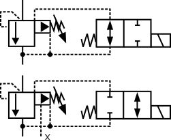
Safety valves direct, pilot operated and cartridge execution with inductive position or proximity switches conforming to Machine Directive 2006/42/CE Safety valves are designed to fulfil the safety criteria imposed to machine manufacturers by the European Machine Directive. They are CE marked and certified by TÜV, in accordance with the technical safety requirements provided in the Machine Directive 2006/42/CE but not included in the safety components of annex IV. In addition to the normal hydraulic function they are equipped with inductive or proximity switches; with the on/off switch indicates the position of the spool/poppet of the valve. These valves are normally used to cut off the hydraulic power line in case of emergency condition, thus avoiding dangerous movements of the machines actuators. By checking the switch status, corresponding to “open” or “intercepted” hydraulic line, the machine controller can perform the safety function. Two versions are available: - FI inductive proximity switch ቢ; - FV inductive position switch (double contacts) ባ; see section 14 for technical characteristics. Safety valves are available in direct, piloted and cartridge executions, with same hydraulic and electric characteristics of standard products from which they are derived. Typical application is on vertical and horizontal presses to shut off the fluid energy to one or more actuators as a consequence of the opening of the machine “gate” or as a consequence of an “emergency stop” command. For details about the applicable EN standards, see www.atos.com, catalog on line, section P, table P004. RANGE OF VALVE’S MODELS DC solenoids Valve code Switch type direct operated solenoid valves, on-off, single solenoid direct operated solenoid valves, on-off, double solenoid direct operated solenoid valves, on-off, single solenoid direct operated solenoid valves, on-off, double solenoid direct operated solenoid valves, on-off, single solenoid direct operated solenoid valves, on-off, double solenoid piloted operated solenoid valves, on-off, with DHE or DHI pilot intermediate elements with cartridge, to be coupled with a specific cover on-off cartridges on-off active cartridges
MODEL CODE OF DIRECT OPERATED SAFETY SOLENOID VALVES /* Seals material: omit for NBR (mineral oil & water glycol) PE = FPM Type of solenoid valve DHI, DHE = direct, size 06 (see tab. E010, E015) DKE = direct, size 10 (see tab E025) Series number Size ISO 4401 0 = size 06 (DH*) 1 = size 10 (DK*) Voltage code, see section 15 Valve configuration, see section ݙ 61 = single solenoid, central plus external position, spring centered 63 = single solenoid, 2 external positions, spring offset 67 = single solenoid, external plus central position, spring offset 71 = double solenoid, 3 positions,...
MODEL CODE of pilot operated safety solenoid valves /* Seals material: omit for NBR (mineral oil & water glycol) PE = FPM Two stage directional control valve Solenoid pilot valve: I = DHI for AC and DC supply with CURUS certified solenoids E = DHE for AC and DC supply, high performances with CURUS certified solenoids Valve size: 1 = 10 Series number Voltage code, see section 15 Valve configuration, see section :ݜ 61 = single solenoid, center plus external position, spring centered 63 = single solenoid, 2 external positions, spring offset 67 = single solenoid, center plus external...
SAFETY VALVES IN CARTRIDGE EXECUTION (MADE BY INTERMEDIATE ELEMENT AND COVER) 8.1 MODEL CODE FOR INTERMEDIATE ELEMENT INCLUSIVE OF THE CARTRIDGE /* Seals material: omit for NBR (mineral oil & water glycol) PE = FPM Intermediate element (with poppet position detector) including the cartridge Series number Type of switch: I = inductive proximity switch Size (ISO 7368), the same of the cover - see section 24 16; 25; 32; 40; 50 Other dimensions available on request /NC = closed contact with poppet in resting position Spring cracking pressure: Type of poppet, see tab. H030 for Q/Δp diagrams 42 =...
MODEL CODE OF SAFETY VALVES IN CARTRIDGE EXECUTION (INTEGRAL DESIGN COVER) Safety cartridge valve according to ISO 7368 Only for LIDAH X = Voltage code see section 15 poppet type: 43 = with damping nose, area ratio 1:2 (size 16 and 25) 1:1,6 (size 32,40 and 50) Only for LIDAH without solenoid connectors to be ordered separately (see tab. K500) spring cracking pressure: 1 = 0,6 bar 3 = 3 bar 6 = 5,5 bar LIDAH-**43/FV Pilot solenoid valve -I = DHI for AC and DC supply, with CURUS certified solenoids -E = DHE for AC and DC supply, high performances, with CURUS certified solenoids Type of...
MAIN CHARACTERISTICS Installation position Subplate surface finishing Roughness index Ra 0,4 - flatness ratio 0,01/100 (ISO 1101) Ambient temperature Recommended viscosity Fluid contamination class ISO 4406 class 21/19/16 NAS 1638 class 10, in line filters of 25 μm (β10 >75 recommended) _ Fluid temperature Flow direction As shown in the symbols of tables ݙ P, A, B = 350 bar T = 100 bar (version /FI); 210 bar (DC solenoid - version /FV); 160 bar (AC solenoid - version /FV) P, A, B = 350 bar T = (with Y port not connected to tank) 100 bar (version /FI); 210 bar (DC solenoid - version /FV);...
STATUS OF OUTPUT SIGNAL FOR DIRECTIONAL VALVES Configuration 67 HYDRAULIC CONFIGURATION high level low level high level low level high level Diagrams show the behaviour of the output signal for inductive switches type FI/NO. For inductive switches type FI/NC the behaviour is opposite (high level signal instead of low level signal and viceversa) (1) According the criteria of safety specifications, the spool position signal must change its status during the intermediate position between two hydraulic configurations. Note: FV versions can be electrically wired by the customer as NO or NC and...
DIMENSIONS of DKE SOLENOID SAFETY VALVES [mm] DKE-16*/FI (DC) DKE-17*/FI (DC) dotted line ISO 4401: 2005 Mounting surface: 4401-05-05-0-05 (without port X) Fastening bolts: 4 socket head screws M6x40 class 12.9 Tightening torque = 15 Nm Seals: 5 OR 2050. 1 OR 108 Ports P,A,B,T: Ø = 11.5 mm (max) Ports Y: Ø = 5 mm Mass: kg 4,4 (one solenoid) kg 5,8 (two solenoids) P = PRESSURE PORT A, B = USE PORT T = TANK PORT Y = DRAIN PORT For the max pressures on ports, see section 16 Mass: kg 3,7 (one solenoid) kg 4,4 (two solenoids) DIMENSIONS of DPH* PILOT OPERATED SAFETY VALVES [mm] DPH*-1/FV switch...
Throttle Body Valve is a type of butterfly valve that is located between the air intake manifold and filter. Air Throttle Valve controls the amount of air that can enter the car depending upon the driver"s input through the gas pedal. Throttle Body Butterfly Valveis a flat valve that is controlled by a pedal. The pressure difference between the exhaust and intake valve timings and engine speed affects the amount of residual gas. Operation of Exhaust Throttle Valve increases the pumping loss and exhaust gas temperature. When the flow of the pump is regulated by Hydraulic Throttle Valve the system curve changes.
The operating point shifts to the left flow is decreased. A pneumatic Throttle Valve is used to control the flow of air from the driver device. The flow of air from side A to side b can be controlled but the inverse is not possible. To precisely control the idle speed in a vehicle Electronic Throttle Valve is used. This is controlled by changing the Throttle Valve In Diesel Engines" electrical polarity. the throttle Valve 6.7 Cummins sits between the truck"s intake horn and the exhaust. 6.7 Cummins Throttle Valve works with the EGR system to recirculate exhaust gas through the intake by lower pipe emission.
Throttle Valve In Hydraulic System to control the flow of hydraulics. Moreover, Throttle Valve Are Used In Mcq as well. We have been producing these 12v Cummins Throttle Linkage and valves for generations and have been following the international standards
Valves are basically used to control or regulate the flow of the fluid in a particular system. One such valve is the Throttle Valve that is used to control the amount of air that flows through the engine. The throttle Control Valveis similar to the pedal of the car. It creates a closed loop control system to ensure that the throttle is open. One of the advantages of an electronic Throttle Check Valve is that it can be linked to systems like traction control, engine control, cruise control, and electronic stability control. Throttle valve manufacturersrecommend these valves since the other systems can take control of the throttle when required thus improving fuel efficiency, vehicle safety, and convenience.
valves operation that can alter the liquid stream rate inside the circuit is analyzed in this paper. A 3D demonstrate for a valves unit was built and presented into numerical examination utilizing ANSYS CFX. Based on the characterized approaching information the show operation was analyzed and the comes about are displayed in arrange to highlight how the parameters changes when utilizing the throttle valves inside the pressure driven circuit.
These valves constrain the stream rate through the valve to a indicated esteem in a client chosen course. A stream rate is utilized to control the operation of a flow control valves.
Thrust Lever Control Valves reenact minor misfortune components whose head misfortune characteristics alter over time. With a Thrust Lever control valve, the minor misfortune "K" is balanced based on a few other framework stream or head.
Thrust Lever Check valves are utilized where volume streams have to be be infinitely controlled in one heading whereas permitting for complimentary stream within the switch heading. A commonplace utilize is the speed control of barrel or other actuators. The free flow check permits for meter-in or meter-out actuator control.
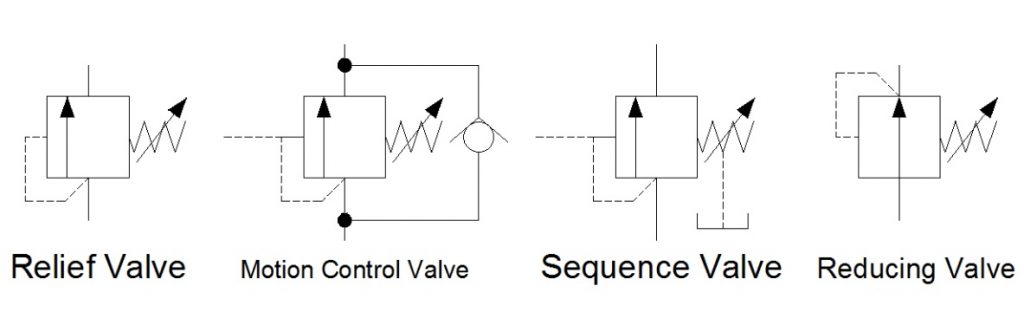
Directional air control valves are the building blocks of pneumatic control. Symbols representing these valves provide a wealth of information about the valve they represent.
Symbols show the methods of actuation, the number of positions, the flow paths and the number of ports. Here is a brief breakdown of how to read a symbol:
position to another. The Position and Flow Boxes indicate how the valve functions. Every valve has at least two positions (learn more) and each position has one or more flow paths, thus every valve symbol has at least two Flow Boxes to describe those paths.
flow path(s) of the valve. In the example above, when the leveris not activated, the spring actuator (right side) is controlling the valve, and the box adjacent to the spring shows the flow path. When the lever is actuated, the box next to the lever shows the flow path of the valve.
In the example below (a three position valve), the "spring return" actuators on both sides return the valve to the center position but only IF neither of the solenoids is active:
With this three position valve, the center position shows the flow path when neither actuator is active, and the springs are holding the valve in the center position). In this fairly common example, the center box indicates that there will be no air flow (i.e. the cylinder will "hold position") unless one of the two actuators is active. This can be used to "bump" or "inch" a cylinder incrementally along its extension or retraction stroke for various purposes.
just show different states of the same valve). In the example at right, there are a total of 5 ports. Learn more about the number of ports here. NOTE: Sometimes a port (usually an
exhaust port) goes directly to atmosphere and there is no mechanical means for attachment of silencers, flow control valves, or any other accessories. To indicate this (in some flow diagrams), ports with attachment capability will have a short line extending beyond the
Valves are also refered to by the number of "ways" that air can enter or exit the valve. In most situations the number of ports and ways are the same for a given valve, but take a look at the 3 position example above. It has five ports, but it is considered a 4 way valve because two of the ports share the same exhaust function. This is a holdover from hydraulics - where the two exhaust paths are joined (internally to the valve), so that only one exhaust port is required, and only one return line is required to get the hydraulic oil back to the storage tank for re-use. The single return port (exhaust) is only counted as a single "way". In the case of our pneumatic valve (above) with similar functionality, the separate exhaust ports are created for mechanical simplicity (and as a cost saving measure), but they are not considered distinct "ways". The symbols above (and on this page) detail many of the ports, ways, and positions of common pneumatic valves. The specification for "ways" can be somewhat tricky; analyzing the circuit symbols is a better method for verifying that a given valve offers the required functionality.


 8613371530291