
hydraulic safety valve symbol quotation
Hydraulic circuits can be comprised of an infinite combination of cylinders, motors, valves, pumps and other equipment connected via hydraulic pipes and tubes. The complexity of these components are difficult to represent fully, so a family of graphic symbols have been developed to represent fluid power components and systems on schematic drawings.
The symbols do not identify component size or their actual position on the machine, however the symbols do provide vital information relating to the configurations and flow path connections.
Below we have summarised some of the most common symbols you may come across. Our technical sales engineers will be happy to help should you need any further help and assistance. Please get in touch on +44 (0)845-644-3640.
Engineers use control valve symbols to identify the type of control valve they want to specify for a given application. In this article, we will identify the most commonly used control valve symbols.
The control valve symbols on a P&ID differ depending on the type of valve specified for the application. Each P&ID has its own legend that identifies the symbols for the various equipment.
An engineer may also include specific details below the control valve symbol. These details may include the size, function, pressure rating, and connection type of the valve.
To enable engineers to communicate and understand the circuitry associated with hydraulic systems there is an International Standard for hydraulic symbols – ISO1219/1 2006
The symbols do not identify component size or their actual position on the machine however the symbols do provide vital information relating to the configurations and flow path connections.
Hydraulics engineers regularly encounter these diagrams, but these symbols can be daunting to interpret if you have limited experience with schematics and the fluid power industry.
On this page, Carr Lane ROEMHELD provides a comprehensive table outlining the definitions of each symbol used in a hydraulic diagram. Engineers can use this page as a reference to determine common schematic symbols used in fluid power, hydraulics, pneumatics, diagrams and circuits.
In order to interpret hydraulic circuit diagrams, it"s important to know what the basic symbols are and what they mean. This post is meant for beginners, but can also serve as a good review and reference for those more experienced with reading hydraulic schematics.
The purpose of a hydraulic circuit diagram is to show how different components are interacting within a system. The circuit diagrams usually differ in appearance significantly from the physical hydraulic setup because circuit diagrams are intended to be a more abstract representation.
Hydraulic circuit diagrams are very similar to electrical circuit diagrams. Electrical diagrams have lines that represents electrical connectors between components. In a hydraulic circuit, the lines represent connectors that allow fluid to flow between components. Electrical circuits symbols representing electrical components (resistors, power sources, transistors, etc.) and systems. For a hydraulic circuit, the symbols represent components (valves, pumps, motors) and systems. And both use industry standard symbols for components, which for hydraulic diagrams would include things such as valves, pumps, motors, and tanks.
A hydraulic reservoiris used to hold the hydraulic fluid needed by the system. These reservoirs, or tanks as they are often called, can either be above or below the fluid level, and either pressurized or non-pressurized.
A check valve has quite a few different names, including one-way valve, retention valve, non-return valve, foot valve, and reflux valve. It"s operation is quite simply: is allows fluid to flow through in one direction only. These valves have two ports: one for the fluid to flow in, and the the other for the fluid to flow out.
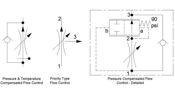
Flow control valves automatically adjust flow rates based on factors such as temperature and pressure. They can range from very simple components to extremely complex electromechanical devices.
Pressure, temperature, and flow rate are key characteristics of hydraulic fluid as it proceeds through a system. Venturi meters are a specific instrument used to measure the flow rate of a fluid.
We usually think of ports as the point of connection that makes pumps, hydraulic motors, etc. a functioning part of a hydraulic system. When you see the simple for a port in a hydraulic circuit, it represents the beginning or end of a passage of fluid flow. Multiple ports are combined into a manifold.
There are a variety of symbols for hydraulic pumps and hydraulic motors, and that makes sense because there are several different types. Based on the symbols present, you can tell at a glance is the pump/motor is fixed-displacement or variable displacement, as well as whether they are unidirectional or bidirectional.
Referring to the hydraulic circuit diagram for a piece of equipment can be extremely helpful when troubleshooting a hydraulic system. While this is certainly not an exhaustive list of hydraulic symbols, it does provide good foundation to begin studying hydraulic circuit diagrams.
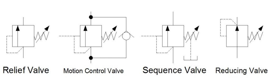
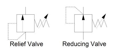
In Hydraulic Symbology 101 (read it here first), I covered the basic square used for pressure valves and also showed the most stripped-down versions of the two most commonly used pressure valve symbols, the relief valve and the pressure reducing valve. In this edition of Hydraulic Symbology, I’m going to cover the four primary pressure valves; the relief valve, motion control valve, sequence valve and reducing valve. Each is based on the same square symbol but are used quite differently in both circuits and real-life function.
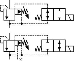
Shown below are the quartet referenced from the same angle as each other. Each shows the basic square with a vertical arrow, abreast of a pilot line to the left and a spring to the right. The dashed line stands for a pilot signal, which is a fluid column of pressure energy used to push or act upon other components internal to the valve. The relief valve is normally closed (non-flowing). As pressure rises in the bottom port, energy pushes around to the pilot line to the left, but the valve is still closed. As the pressure continues to increase, the force pushing against the left side of the arrow starts to overcome the spring force applied from the right. When pilot pressure creates enough force, it can overcome spring pressure to slowly open the valve.
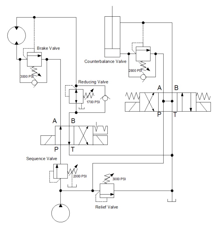
The below example shows a circuit with all four types of pressure valves used. It looks like a lot going on, but I’m going to break them all down one by one so they make sense. The relief valve teed into the right after the pump is drawn just as the relief valve above, and it operates under the same principle. The spring is pushing the valve closed with 3,000 psi of force, and in this circuit, it acts as the maximum limit pump pressure can achieve before being exhausted to tank.
Sequence valves are not much different from relief valves, and this is at once obvious by their similar appearance. This sequence valve downstream of the pump is exactly the same as the relief save for the drain line and reduced pressure setting. A sequence valve is purposed to provide a secondary flow path which occurs in sequence to a parallel function. In other words, when the cylinder in this application extends to the end of stroke, pressure will rise immediately. When pressure hits 2,000 psi, our sequence valve opens, diverting all pump flow to rotate the motor while the cylinder remains stalled and as long as its directional valve remains energized.
The sequence valve drain line is required to keep the valve’s performance consistent. Because the sequence valve experiences pressure on both ports, internal leakage allows pressure buildup inside the spring chamber which is additive to spring pressure. Without a drain, the pressure setting could rise or the valve could even lock up altogether. The key difference between a sequence valve and relief valve is the existence of this drain. A sequence valve makes an outstanding relief valve, in fact.
The pressure reducing valve is plumbed in just past the directional valve in the B-port. You’ll notice immediately how different this valve is than the others, and the extra astute will have noticed two differences, actually. The pilot line is drawn differently, this time showing its pressure signal originating downstream of the valve. This important contrast allows the valve to reduce downstream pressure to protect the actuator or sub-circuit beyond.
The reducing valve also differs in that it is normally flowing in its neutral state. Fluid is free to pass and allow the motor to spin, and not until downstream pressure from the motor rises to above the 1,700 psi setting of the valve does is start to close. The pilot line senses downstream pressure and starts to move the arrow to the right, choking flow to the motor. This reduced flow also reduces pressure, but it does so smoothly and with little drop in velocity. The effect is that downstream pressure is simply reduced.
You’ll notice in this example, there is also a check valve allowing flow to bypass the reducing valve altogether. This ensures the motor will experience little or no backpressure when it rotates in the opposite direction. Sometimes the reverse-flow check valve is not required, but it makes for good practice.
The last pressure valve to be discussed today is the motion control valve, which in my example is broken down into the brake valve and the counterbalance valve. The brake valve is used in motor applications as seen above. The valve is also very similar to the relief valve in design, and in fact, could still be used as one (as is the case for all pressure valve aside from the reducing valve). The reverse flow check valve allows free flow into the motor, allowing it to freely spin clockwise when the directional valve is left in its current detented position.
When the directional valve is reversed, however, the check valve blocks free flow and oil must now flow through the brake valve. This valve, you’ll notice, has two separate pilot lines merging at the same point on the valve. It has the same direct acting pilot line that rounds the corner, but there is an additional pilot source drawn from the opposite port of the motor. These dual pilot sources add interesting functionality to the brake valve in that it is both internally and externally piloted.
The internal, direct-acting signal will ensure the motor won’t move until a combination of load and pump pressure pushes through the motor to the tune of 3,000 psi. This allows the motor to stay “braked” while pump flow is non-existent. However, a direct-acting brake control valve is an inefficient method to control motion.
This valve has a trick up its sleeve — the surface area the external pilot works against is larger than the area of the direct acting side. The ratio of areas is often 4:1 but can be upwards of 8:1. The result is the pilot pressure needs to a quarter of work pressure, reducing energy lost to the brake valve. The brake valve is essentially braking to the tune of 3,000 psi, but opening to provide flow when the opposite port sees 375-750 psi. The valve uses pilot pressure as permission to open and allow flow, preventing unintended movement of the motor.
Lastly, we arrive at the motion control valve labelled counterbalance valve. It’s typically one and the same as a brake valve but used in cylinder applications. This example shows a relief valve set to 2,800 psi and is plumbed to the cap port of the cylinder. The reverse flow check valve ensures the cylinder will extend with little pressure drop, but when the directional valve is placed back in neutral, the counterbalance valve remains closed so the cylinder will not accidentally retract.
The counterbalance valve also has a pilot ratio enabling the valve to open once it senses pilot energy from the rod port, preventing accidental retraction. Counterbalance valves also work well on the rod port of a cylinder, which prevents overrunning loads as a cylinder moves “over center,” which is a condition of pulling forces on the rod.
Both examples of these motion control valves could have been employed with spring chamber drain ports, just as with the sequence valve. The drain keeps the spring chamber free from additional pressure, but in the case of this circuit, the open line to the reservoir through directional valves is enough to prevent excessive pressure. It’s when both ports of the pressure valve are continuously pressurized that a drain or vent is absolutely required.
There are many variations of pressure valves not covered here, but those will be discussed in a later episode. In Hydraulic Symbology 204, I’ll cover the essentials of flow control valves, including how they’re drawn and where they’re used.
The improper installation of pressure relief devices can have dire consequences, causing unnecessary safety risks, and delaying operations while they are replaced or repaired. PRVs are typically one of the last lines of defense in an upset condition. To ensure that PRVs relieve and flow properly, the ASME and the National Board certify all PRV assembly programs, testing facilities, and even technicians. When you see marks and symbols on your pressure relief devices, it means that your device is certified safe because it came from a National Board and/or ASME certified organization.
The National Board sets the industry standards for pressure relief devices and is responsible for markings and symbols on their pressure relief devices are those that:
The five symbols in the above graphic above are issued by the ASME and National Board. There are others, and you may see a few different variations from time to time. Each of them denotes a specific certification:
The National Board offers the Certificate of Authorization and the “R” symbol stamp for the repair and/or alteration of boilers, pressure vessels, and other pressure-retaining items.
The simple answer? Safety. However, there’s a bit more to safety than you might think. In order to ensure safe operation, organizations like the ASME and National Board set firm standards and require the completion of specific programs to attain certification. These programs are rigorous, and the UV Assembly Program is no exception. It’s designed to be very stringent, as it ensures consistency in the capabilities and functionality of all components in the PRV assembly process. Ideally, a PRV should be procured from a certified assembler that is also able to test and repair the device if necessary. Unfortunately, this is a tall order that not all suppliers are able to.
Vinson Process Controls has the capabilities and credentials required to assemble, test and repair pressure relief devices. In order to better serve our customers, we earned the certifications for the UV (assembly program), VR (valve repair) and T/O (testing only) certifications from the ASME and the National Board. We take the guesswork out of PRV procuring and maintenance so that our customers can relax and reap the benefits.
As a UV-certified assembler, Vinson has invested in stocking Anderson Greenwood™ and Crosby™ relief valves for faster lead times. We have a wide range of options for our customers, including same-day service, when required. The vast majority of Vinson’s relief valve inventory is in the portable 81P valves and pilot operated valves. Apart from the combined inventory we share with Emerson, we also have access to shared inventory across all 21 of Emerson’s Impact Partners. We are proud to say that all valves assembled in our Carrolton Valve Center have met or exceeded expected shipping dates.
In addition to faster lead times, our customers can maintain confidence that the products shipping from Vinson are of the samequality as those shipping directly from Emerson’s factory. The ASME, the National Board and Emerson audit all shops, quality control processes, techniques, and valves, before and after awarding certifications. Vinson will continue to receive audits to ensure that we are meeting or exceeding expectations over time. Our adhesion to our quality control manual means that all valves assembled by Vinson have the same factory warranty as if they were assembled in Emerson’s production line.
As a part of the Emerson Impact Partner Network, Vinson is one of the primary points of contact for direct sales of Anderson Greenwood™ and Crosby™. We are a certified UV assembler, also offering valve repair and testing services. We can offer you quotes for both repair and replacement options. Because of this unique status, Vinson can offer competitive pricing.
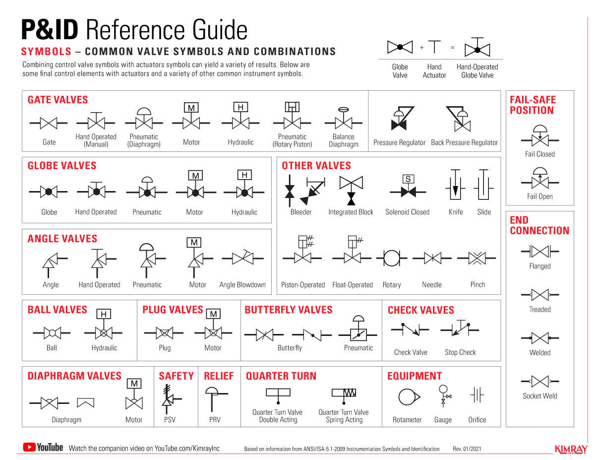
Piping and instrumentation diagrams (P&IDs) are conceptualized during the development and design stages of chemical, physical, electrical and mechanical processes. Everything from ball valve symbols to communication lines are included in a P&ID in order to lay out the proper direction for a process control installation.
In this article, we highlight some of the most common P&ID valve symbols, process lines, end connections and other vital components. Before you dive in, download a PDF version of the symbols listed in this article.
The symbols for these components aren’t drawn to scale and aren’t intended to be dimensionally accurate. Symbols can also be marked with words, letters and numbers for more detail.
The International Society of Automation (ISA) created the ANSI/ISA-5.1-2009 standard that defines the proper ways to use symbols in a P&ID. Although these standards are in place, there may be variations of certain symbols used across industries or companies. But, since all components in a P&ID use text or numbers for further identification, having a basic understanding of the symbols should not be an issue.
A 2-way, on/off valve is symbolized by two equilateral triangles that point toward each other. These valves use varying types of lines to represent different types of valves. The direction of the flow is shown by an arrowhead at the end of the line.
For multi-port valves, additional triangles are added to the symbol. L-port and T-port valves are depicted by lines within the ball symbol. The flow path is depicted by small arrows by the symbol.
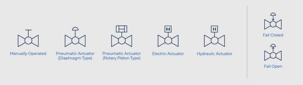
The type of actuation is depicted with lines protruding from the center of the valve. A small symbol appears on top of the line for further identification. Electric and hydraulic actuation are shown with letters.
The type of connection for a valve (flanged, threaded, welded or socket weld) is displayed using perpendicular lines, circles and squares. For example, the perpendicular lines in a flanged connection show that the valve can be removed without affecting the pipe. Unfilled circles represent temporary threaded connections while permanent welded connections are depicted by filled-in squares. Socket welded connections are displayed using unfilled squares.
Gemini Valve manufactures, distributes and supports a full selection of performance-engineered ball valve products, including custom ball valves. For more information or to speak with a specialist, contact us here.
- when the line pressure reaches the setting of the valve, valve opens permitting flow to the secondary port. The pilot must be externally drained to tank.

A piping and instrumentation diagram (P&ID) is a graphic representation of a process system that includes the piping, vessels, control valves, instrumentation, and other process components and equipment in the system. The P&ID is the primary schematic drawing used for laying out a process control system’s installation. As such, the P&ID is crucial in all stages of process system development and operation.
There are standard symbols used to represent the components in these diagrams. It is important to note that these symbols are NOT to scale and are NOT dimensionally accurate. They are merely used to represent a certain type of component. These symbols are also labeled with words, letters, and numbers to further identify and specify the components that they are representing. Another important consideration is that the diagrams do NOT always represent the physical locations and proximity of each component. The purpose is NOT to serve as a floor plan or map of the system, it is to illustrate the process of the system.
The generic symbol for a 2-way valve is two triangles pointing to each other with the tips of the inner points touching. The pipe lines are represented by lines connecting to each side of the valve symbol. Various types of lines are used to represent different pipes, tubes, and hoses. These examples use single solid lines which represent simple rigid pipes or tubing. Typically all pipes will run either vertically or horizontally and use only right angles. The direction of flow is indicated by an arrowhead at the end of the line where it meets the next component as well as at every 90 degree turn.
All of the valves represented above are 2-way inline valves that are used for flow control, either on/off or throttling. For Multi-port valves, such as 3-way and 4-way, the structure of the symbol is similar, having a triangle to represent each port or “way”.
3-way and 4-way ball valves can contain additional detail that defines the type of ball drilling which is either a “T” or “L” port ball. Another detail that may be represented in the diagram is the flow path in the non-actuated or de-energized state. This is shown using small arrows next to the symbol as shown below.
The method of actuation is defined by a line coming up from the center of the valve with a small symbol, many times containing a letter, at the top of the line. Here are some examples of ball valves with different methods of actuation.
When the actuator has a fail-safe position, it is represented by an arrow on the line between the valve and actuator. Another method used to represent the fail position is with two letters “FO” or “FC”.
End connections can be represented generically with the lines representing the pipes going directly into the valve as in all of the examples above. Connections may also be explicitly defined using various other methods. Flanged connections are represented as shown below – where the pipes have perpendicular lines at their ends that run parallel to the sides of the valve symbol with a small space between them. This illustrates that the valve can be removed without cutting the pipe. Semi-permanent threaded connections are shown with small hollow circles at the connection point. Permanent welded connections are represented with small squares instead. If the connection is socket weld, the square is hollow or un-filled.
Despite the fact that there is a strict set of standards defined for these symbols, you will find various ways of representing certain valves. You will also find that there are blatant discrepancies between some valve types across various libraries, industries, and companies. This issue is not that problematic since all components are also described by text, a part number (unique model), a tag number (specific component in the system), and are defined in detail in a key or legend that goes along with the drawing. As long as you remain consistent throughout your drawings, the P&ID diagram will be acceptable and understandable by all who work with it.
The list goes on and on… There are literally hundreds of symbols that represent all components used in process control systems. Heat exchangers, coolers, boilers, filters, etc.etc. We have created a library of P&ID symbols that includes the most common components used in piping and instrumentation diagrams.
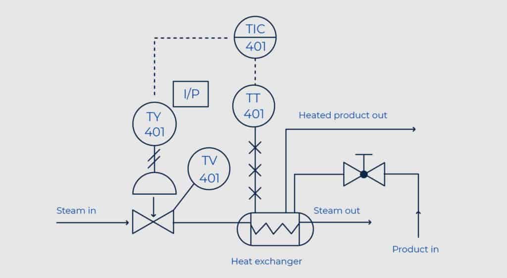
This type of bubble is also used to define the function of final control elements such as valves. This is done with a callout line pointing to the symbol for the control element. The letters and numbers inside the bubble are described below.
This is followed by loop number, which is unique to that loop. For instance FIC045 means it is the Flow Indicating Controller in control loop 045. This is also known as the “tag” identifier of the field device, which is normally given to the location and function of the instrument. The same loop may have FT045 – which is the Flow Transmitter in the same loop. Below are some examples of complete symbols for a few instruments in the same loop.
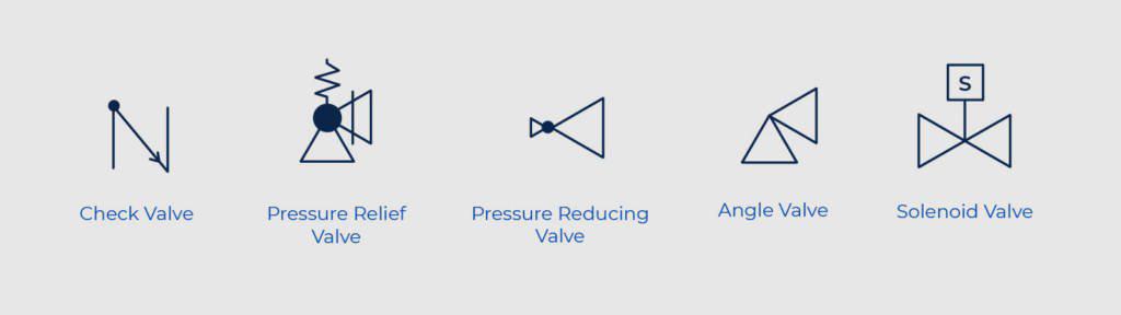
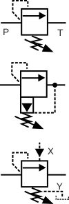
Pressure reducing valve symbols look very similar to those for pressure relief valves. This is because the valves work in similar ways except that the pressure sense line feeds from downstream of the reducing valve instead of upstream as in the relief valve. This means that the reducing valve controls the downstream pressure rather than the upstream pressure. As such the reducing valve cannot generate a downstream pressure that is not there but it can limit its value. Not how the arrow is shown in the middle positions indicating that it is normally open but closes the flow off when the pressure feed forces the arrow against the adjustable spring.
The middle symbol has a third tank line port and arrowheads pointing in both directions. In this valve, if the pressure downstream rises above the reducing valve"s setting then the valve will vent this pressure down the third line to provide a constant pressure in the sensed port.


 8613371530291