
hydraulic safety valve symbol for sale
![]()
Searching for tools to control the flow of your piping system? Explore one of the largest featured collections of products and discover a range of wholesale check valve symbol on Alibaba.com. When you search for check valve symbol and related items, you will be able to find many types of check valve symbol varying in size, shape, use, and quality, all at prices in which are highly reasonable!
There are many uses of valves - mainly controlling the flow of fluids and pressure. Some examples include regulating water for irrigation, industrial uses for controlling processes, and residential piping systems. Magnetic valves like those using the solenoid, are often used in a range of industrial processes. Whereas backflow preventers are often used in residential and commercial buildings to ensure the safety and hygiene of the water supplies. Whether you are designing a regulation system for irrigation or merely looking for a new replacement, you will be able to find whatever type of check valve symbol that you need. Our products vary from check valves to pressure reducing valves, ball valves, butterfly valves, thermostatic mixing valves, and a lot more.
![]()
To enable engineers to communicate and understand the circuitry associated with hydraulic systems there is an International Standard for hydraulic symbols – ISO1219/1 2006
The symbols do not identify component size or their actual position on the machine however the symbols do provide vital information relating to the configurations and flow path connections.
![]()
In this article, you are going to learn about different types of valve symbols used in P&ID. Many types of valves are used in process piping, and each has a different symbol. This makes the valve one of the tricky parts of reading P&ID. But with practice, you can easily remember these symbols and can read P&ID effectively.
There are two types of valve symbols — first, generic symbols, and second, a symbol with a modifier. Generic symbols will tell you that there is a valve in the line, but they will not tell you about the types of the valve. Whereas the valve symbol with modifier will tell you the type of valve used in the pipeline.
Here in the image above, you can see commonly used symbols for valves. These symbols are generic in nature — for example, the first symbol of a valve.
Now when you look at the symbol on the drawing, it just gives you an indication that some kind of valve is used, but it will not provide you with information about the type of valve, whether it is a gate, globe, or plug type valve. There are dedicated symbols for a gate, globe, plug, and ball valves which I will explain to you in minutes.
Similarly, the next two symbols are for three-way and four-way valves. It can be a plug or ball valve. The subsequent two symbols are a check valve and a stop check valve. These check valves can be swing check or lift check valves.
The next symbol is the excess flow valve. You can see that it is the same as a check valve the only difference is the written text below the valve symbol. You must be very careful while reading this type of symbol as it can easily be overlooked.
The last symbol is of automatic recirculation valve. This type of valve is used in the pump discharge line to ensure the pump will not suffer from low inlet pressure, which leads to cavitation.
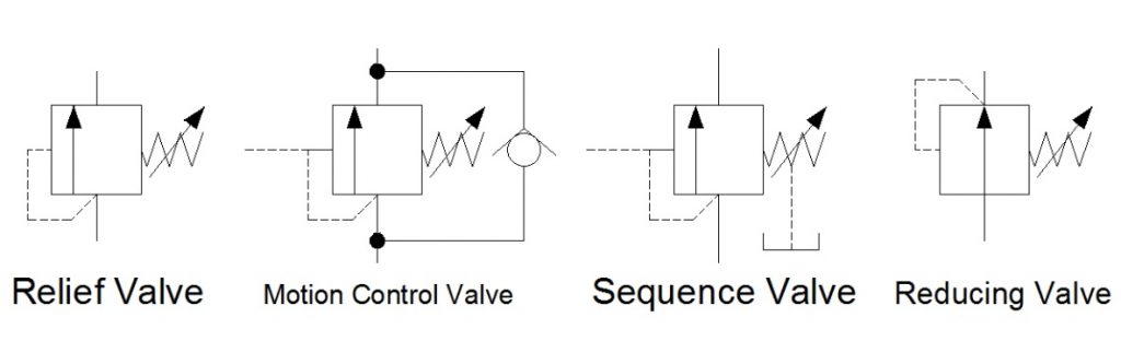
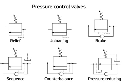
Here in the image above, the first symbol is of angle valve. In most cases, a globe valve is used as an angle valve. The next symbol is the relief valve used to protect the piping system or equipment from overpressure.
Now the breather valve is used on the cone roof tank. This valve serves the function of the relief valve and vacuum valve. In the event of over-pressure, this valve release the pressure, and in case a vacuum is created in the tank, this valve allows air to enter the tank. Just like breathing air in and out.
The vacuum valve prevents damage to the equipment from negative pressure. Pilot-operated relief valves are just working as relief valves but are used for large-size piping. This type uses a small relief valve to operate the main relief valve. This arrangement is cost-effective in large-size relief operations.
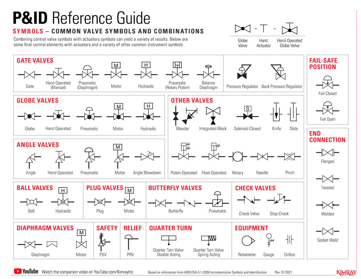
In the image above, you can see the gate valve. Now see the P&ID symbol for the gate valve. It is a modification of a generic valve symbol by inserting a vertical line between two triangles. Three symbols shown below are the gate valve symbols used in isometric drawings. The first is for butt-welding ends, the second is for flanged end valve, and the third is for socket end connection.
For a globe valve, a symbol is modified by adding a small dark circle between triangles. You can see that P&ID and isometric symbols are almost the same, with the only change in end types.
You can see that there are two P&ID symbols for a ball valve. The reason is that P&ID and isometric drawing symbols are changed from company to company. So if you switch the company, you should be aware of this. Similarly, you can see the ISO symbols for butt, flanged, and socket ends ball valve.
Same as a ball valve, a needle valve also has multiple P&ID symbols. If you can see that even though these symbols are different, you can still easily interpret them. If you are using second P&ID symbols, your isometric symbol will be changed accordingly.
For the plug valve, the first symbol is a bit confusing with a globe valve. If you remember the symbol of a globe valve, it has a dark circle in between the triangle, whereas here, only the circle outline is there. So when you see this type of symbol, better to double-check the drawing.
The butterfly valve symbol is the only symbol where a full triangle is not used. If you refer to the first symbol, it is similar to a globe valve, but a triangle is not full. The alternative symbol is clearer in this case. For isometric symbols, you can see that there is no socket end butterfly valve.
Here is the diaphragm valve. There is no butt-welded diaphragm valve available. Most diaphragm valves are flange type, and they are used to handle process media with solid particles.
You can see the symbols in the image above with a special note. The first symbol is a special valve. The word NC return below the second symbol is more important. It indicates that this valve remains closed during normal operation. Now the next two symbols are also used alternatively to show the valve position during normal operation.
Hydraulic Right Angle Check Valve. | SEVEN OCEAN HYDRAULICS - A world-class manufacturer of high performance hydraulic valves, power units and accessories.
Located in Taiwan since 1989, SEVEN OCEAN HYDRAULIC INDUSTRIAL CO., LTD. has been a hydraulic valves, power units and accessories manufacturer. Their main products, include Right Angle Check Valve, Solenoid Operated Directional Control Valves, Pilot Operated Directional Control Valves, 4/2 Directional Control Valves, 4/3 Directional Control Valves, Variable Volume Vane Motor Pumps, Modular Stack Valves, Sandwich Valves, Hydraulic Power Units, Hydraulic Pressure Control Valves and Flow Control Valves, which are suitable for forklift, machine tool, plastic injection and recycling electrical machinery industries .
SEVEN OCEAN HYDRAULICS"s Right Angle Check Valve are reliable, sustainable, and cost effective, bringing you long-term value at an affordable price-point. With over 31 years of experience in manufacturing hydraulic systems, valves and components, Seven Ocean Hydraulics is able to streamline production time and has a greater control over product quality with in-house manufacturing of core components. We have gained trust from world- renowned brands for OEM projects, providing essential components for hydraulic products that are seen and used all over the world.
SEVEN OCEAN HYDRAULICS has been offering customers high-quality hydraulic valves, both with advanced technology and 31 years of experience, SEVEN OCEAN HYDRAULICS ensures each customer"s demands are met.

NG6 / Cetop-3 / D03 Modular Stack Pressure Relief Valve. | SEVEN OCEAN HYDRAULICS - A world-class manufacturer of high performance hydraulic valves, power units and accessories.
Located in Taiwan since 1989, SEVEN OCEAN HYDRAULIC INDUSTRIAL CO., LTD. has been a hydraulic valves, power units and accessories manufacturer. Their main products, include Modular Check Valve, Solenoid Operated Directional Control Valves, Pilot Operated Directional Control Valves, 4/2 Directional Control Valves, 4/3 Directional Control Valves, Variable Volume Vane Motor Pumps, Modular Stack Valves, Sandwich Valves, Hydraulic Power Units, Hydraulic Pressure Control Valves and Flow Control Valves, which are suitable for forklift, machine tool, plastic injection and recycling electrical machinery industries .
SEVEN OCEAN HYDRAULICS"s Modular Check Valve are reliable, sustainable, and cost effective, bringing you long-term value at an affordable price-point. With over 31 years of experience in manufacturing hydraulic systems, valves and components, Seven Ocean Hydraulics is able to streamline production time and has a greater control over product quality with in-house manufacturing of core components. We have gained trust from world- renowned brands for OEM projects, providing essential components for hydraulic products that are seen and used all over the world.
SEVEN OCEAN HYDRAULICS has been offering customers high-quality hydraulic valves, both with advanced technology and 31 years of experience, SEVEN OCEAN HYDRAULICS ensures each customer"s demands are met.

Engineers use control valve symbols to identify the type of control valve they want to specify for a given application. In this article, we will identify the most commonly used control valve symbols.
The control valve symbols on a P&ID differ depending on the type of valve specified for the application. Each P&ID has its own legend that identifies the symbols for the various equipment.
An engineer may also include specific details below the control valve symbol. These details may include the size, function, pressure rating, and connection type of the valve.

Below are some common illustrations of equipment located on fluids circuit diagrams, followed by descriptions of the most common elements. Later in this article series we will describe some simple hydraulic and pneumatic circuits composed of these circuit elements.
Needle valves are used to throttle or shut-off flow of fluids. They usually will vary flow with pressure or viscosity change. Some valves can be pressure and/or temperature compensating.
Flow control valves are used to control oil flow in one direction and unrestricted in the opposite direction. "Metered in" control means that the flow controls are controlling the fluid into the actuator, "metered out" is controlling the fluid out of the actuator. Some valves can be pressure and/or temperature compensating.
When the pilot line to a pilot-operated check valve is not pressurized, flow is allowed in one direction but blocked in the opposite direction. When the pilot line in a pilot-to-open valve is pressurized, the check valve is open, allowing flow in either direction.
When the pilot line to a pilot-operated check valve is not pressurized, flow is allowed in one direction but blocked in the opposite direction. When the pilot line in a pilot-to-close valve is pressurized, the check valve is closed, blocking flow in both directions.
Counterbalance valves are used to control overrunning loads and to support loads should a function be stopped at any point throughout its travel. NOTE: this valve is typically preset and should not be tampered with.
Flow fuses are normally open valves which close if the pressure difference between the inlet and outlet valves is too high compared to the design setting. The valve can be reset by reversing the direction of flow. When placed inline with an actuator (for example, a cylinder), flow fuses limit the maximum speed of that actuator.
Directional control valves are used to direct fluid flow into the appropriate lines for the designated operation. These valves are usually electrically controlled.
Hydraulic pumps are used to pump oil from the power unit to other parts of the hydraulic system. Some pumps have control options such as pressure or flow compensators.
Water modulating valves are used for controlling the oil temperature in the reservoir automatically by controlling the volume of water going through the heat exchanger.
Heat exchangers are used to remove heat from the circulating oil in the hydraulic system. The most common heat exchanger is water-to-oil but some times air-to-oil units are used. Coolers will cool the fluid.
Proportional valves are electrically controlled hydraulic valves. These valves proportionally control the hydraulic pressure and/or flow based on an electrical input signal.
For more information about reading hydraulic and pneumatic circuit diagrams, read the next article in this series which describes sample hydraulic circuits, or contact your Valmet representative.

Hydraulic circuits can be comprised of an infinite combination of cylinders, motors, valves, pumps and other equipment connected via hydraulic pipes and tubes. The complexity of these components are difficult to represent fully, so a family of graphic symbols have been developed to represent fluid power components and systems on schematic drawings.
The symbols do not identify component size or their actual position on the machine, however the symbols do provide vital information relating to the configurations and flow path connections.
Below we have summarised some of the most common symbols you may come across. Our technical sales engineers will be happy to help should you need any further help and assistance. Please get in touch on +61 8 8984 4939.
Many types of valves are required in a process plant for flow regulation or on/off purpose. Type of valve employed depends on nature of fluid, flow control required, operating pressure and temperatures as well as surround atmosphere. Here is a list of symbols for various types of valves used in process industry.

The primary purpose of a pressure relief valve is to protect life, property and the environment. Pressure relief valves are designed to open and release excess pressure from vessels or equipment and then close again.
The function of pressure relief valves differs depending on the main type or loading principle of the valve. The main types of pressure relief valves are spring-loaded, weight-loaded and controlled pressure relief valves.
Regardless of the type or load, pressure relief valves are set to a specific set pressure at which the medium is discharged in a controlled manner, thus preventing overpressure of the equipment. In dependence of several parameters such as the contained medium, the set pressure is individual for each safety application.
hydraulic ball valve symbol 1 2 hydraulic ball valve 3/4 hydraulic ball valve hydraulic ball valves high pressure hydraulic ball valve 3 way hydraulic ball valve actuator hydac ball valves stauff ball valves how hydraulic valves work hydraulic valve types hydraulic valve wiki hydraulic valve function hydraulic valve pdf hydraulic valve symbols hydraulic valve symbols meaning hydraulic valve symbols schematics hydraulic cartridge needle valve hydraulic needle flow control valve hydraulic needle valve operation needle valve with reverse check needle valve function needle valve animation needle valve swagelok needle valve application hydraulic operated nrv high pressure nrv nrv 3 8 hydraulic return line check valve parker hydraulic check valve hydraulic check valve types hydraulic check valve function hydraulic inline check valve


 8613371530291