
hydrogen safety valve free sample
Historically and currently, enormous amounts of hydrogen are needed for key industrial processes such as the manufacture of artificial fertilizers and steel. New H2 applications such as fuel cell vehicles would further increase future demand. To contribute to the energy transition, this hydrogen needs to be "green" instead of being derived from fossil fuels, i.e. without producing CO2 in the process.
This will require large hydrogen electrolyzers. These consist of several stacks of electrolysis cells. For safe operation, the individual stacks require protection against overpressure with safety valves.
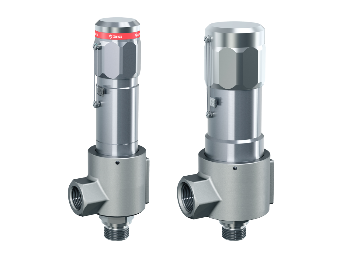
The WITT safety valves AV 619 and AV 919 perfectly match the target pressure and temperature ranges of PEM and Solid Oxide electrolyzers. The opening pressure can be set accurately anywhere in range 5 to 500 mbar. The operating temperature can be anywhere up to 250°C.
Highly precise and reliable, the valves open when the set pressure is reached and safely protect workers and sensitive equipment from overpressure. Despite their small size, the valves allow high flow rates, making them also suitable for large installations.
The valves are available with the elastomers required for hydrogen, including EPDM or FFKM (also known as FFPM). WITT safety relief valves are oil and grease-free, can be installed in any position, and are available with various inlet and outlet connections and in different materials, including stainless steel or aluminum (AV 919). Optionally, WITT offer TÜV Certification of individual valves’ set pressures.
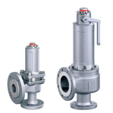
A pressure relief valve prevents a predefined pressure from being exceeded. When the pressure is exceeded, the valve opens and the excess pressure is released and the medium is discharged. The pressure relief valve is activated without auxiliary energy and is triggered purely by the medium.
A pressure relief valve is used to protect a system as a last safety instance. In the case of systems requiring approval or systems that fall under the European Pressure Equipment Directive, for example, corresponding tests and approvals are required for the valves.
Even though each series differs in the field of safety valves, the main components of each valve are similar. The optimal design of the component geometry is ensured by flow simulations and elaborate function tests.
When at rest and installed on the system in normal operation, the force of the pressure spring is greater than the medium force, whereby the valve is closed and seals to the outside.
On the one hand, hydrogen is a colourless, odourless and completely non-toxic gas; on the other hand, it is highly volatile, highly flammable and has a high flame velocity. With hydrogen as a medium, the challenge is to produce, transport, store and use the gas safely, depending on the application and environment. These characteristics of hydrogen pose specific challenges for the design and construction of a hydrogen pressure relief valve.
As the last mechanically acting component in the safety chain, the pressure relief device for hydrogen systems is an important and indispensable part of the process. This applies in particular to the materials and seals used, as well as to the manufacturing process of the hydrogen valve, and the corresponding approvals.
A hydrogen pressure relief valve can be used to safeguard a hydrogen circuit, a hydrogen pressure pipe, or a high pressure hydrogen tank. The final safety chain function of such a high pressure hydrogen relief device is particularly relevant on a compressed hydrogen tank, which needs to maintain safe pressure levels even while the hydrogen system is not in operation, or left unattended.
Oil- and grease-free production, a hydrogen purity of > 5.0 (> 99.999 %), production according to a special production process for technical gases is explicitly recommended.
Which approvals for pressure relief valves are necessary in the field of hydrogen applications?Only use component-tested pressure relief valves to protect your hydrogen pressure systems.Sound technical advice from the valve manufacturer of the high pressure hydrogen relief device is essential in any case. Only then can your specific conditions be taken into account and the hydrogen pressure relief valve can be correctly designed according to the conditions prevailing on site.
For over 70 years, Goetze KG Armaturen has been manufacturing sophisticated high-performance valves and fittings for media under pressure: liquids, air, gases and vapours. The family-owned company, which is based in Ludwigsburg, has made themselves a reputation worldwide with their high level of quality “Made in Germany”. Goetze is your partner regarding safety (valves). We assure the handling of hydrogen from the retrieval to the application – either in the electric part of the process or at the hydrogen filling station for vehicles. We protect filling processes, which are under high pressure or the storage of liquid hydrogen in tanks.
Designed to reduce contaminants in high-purity applications using hydrogen and methane gas, these valves have a stainless steel and brass body with a smooth finish to reduce dust collection and internal components designed to protect the seal and diaphragm from contamination. They’re often used in research sample systems, emission monitoring systems, and chromatography. Valves automatically reduce a high inlet pressure from compressed gas tanks to a lower, stable outlet pressure. All have Compressed Gas Association (CGA) numbered inlet fittings for secure connections to compressed gas tanks. Choose a valve with the same CGA number as your tank and other system components. Outlet fittings are Swagelok® for a leak-free seal around hard metal tubing in high-pressure lines. Also known as instrumentation fittings, Swagelok® fittings are compatible with Parker A-Lok, Gyrolok, Bilok, and Tylok fittings. Valves come with a gauge to monitor outlet pressure and a gauge to monitor inlet pressure from the tank.
Choose a valve with a maximum outlet pressure that’s approximately twice your application’s normal operating pressure. Your operating pressure should never exceed 75% of the valve’s maximum outlet pressure.
Single-stage valves reduce pressure in one step, which causes the outlet pressure to fluctuate slightly as you empty the tank. They’re best for applications where a constant outlet pressure isn’t critical.
Two-stage valves progressively reduce pressure over two steps for more consistent outlet pressure at all times. They’re often used in applications that require a constant outlet pressure regardless of the tank level.

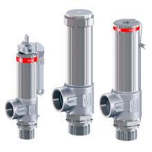
Valves for industrial applicationsIn order to prevent the uncontrolled rise in pressure in pressure vessels or pressurized pipelines, a safety valve is inserted. The safety valve is designed so that it opens at a given maximum pressure, thereby relieving the line or the container. Safety valves find their use in almost all areas of the pressure vessel and pipeline construction. In cryogenics as a spring-loaded safety valve for example.

Through innovative organic development and strategic acquisition, we have built a broad portfolio of ASME and API valves that services the demands of global drilling, production, pipeline, storage, transmission, and critical service applications.

ARKEMA is operating its plant in a non-stop mode requiring a high level of availability of the equipments as utilities devices as compressed air tanks. To allow high availability of its plant, ARKEMA decided to go for LESER’s new Changeover Valves.
The LESER Change-over Valve Type 330 and 320 offers the solution for safe and efficient system availability 24 / 7. It is easy to operate and, in combination with safety valves, provides permanent protection for a permanently running system.
With the help of flow tests and CFD simulations (Computational Fluid Dynamics), a flow-optimized design with minimal pressure loss was developed. Each configuration of these change-over valves has a specified resistance coefficient that enables reliable and precise calculation of the inlet loss. Due to their durable construction, these change-over valves are maintenance-free and lavishly tested. They are the economical solution because an optimal selection can be made for every application.
ARKEMA is one of the leading hydrogen peroxide producers in the world. Hydrogen peroxide (H2O2) is used in different concentrations as example for food packaging sterilization. The plant in Shanghai was established in 2000, and expanded in 2008.

Numerous reviews on hydrogen storage have previously been published. However, most of these reviews deal either exclusively with storage materials or the global hydrogen economy. This paper presents a review of hydrogen storage systems that are relevant for mobility applications. The ideal storage medium should allow high volumetric and gravimetric energy densities, quick uptake and release of fuel, operation at room temperatures and atmospheric pressure, safe use, and balanced cost-effectiveness. All current hydrogen storage technologies have significant drawbacks, including complex thermal management systems, boil-off, poor efficiency, expensive catalysts, stability issues, slow response rates, high operating pressures, low energy densities, and risks of violent and uncontrolled spontaneous reactions. While not perfect, the current leading industry standard of compressed hydrogen offers a functional solution and demonstrates a storage option for mobility compared to other technologies.
To mitigate the progression of climate change, there is an increasing momentum to reduce the global emissions of greenhouse gases. For example, France approved the law no. 2015-992, which requires a 40% reduction of greenhouse gases by 2030 compared to 1990 [15]. Although the use of fossil fuels is not the only source of greenhouse gases, it is certainly a major one. According to the United States Environmental Protection Agency, fossil fuels account for 76% of all U.S. emissions due to human activities [16]. It can be assumed that a significant reduction of greenhouse gas emissions implies the reduction of fossil fuel usage. However, that is not a simple task because products derived from fossil fuels are not just energy carriers, they are also a primary source of energy. Hydrogen is an energy carrier that should be produced by an environmentally clean process in order to have a truly positive impact on decarbonization. In 2017, more than 85% of the energy produced globally came from fossil fuels [17]. Therefore, if the world were to completely switch over to a hydrogen economy that eliminates all fossil fuel consumption, an energy shortage would soon occur [18,19,20,21,22]. This aspect represents a significant problem to find suitable energy sources. However, this topic will not be discussed in this study. Instead, this study focuses on the use of hydrogen as a renewable energy storage medium [23,24,25,26,27].
Renewable energy is theoretically plentiful. Nakićenović et al. [28] estimated the minimum annual solar energy potential to be 1575 EJ, which would exceed the annual global energy consumption by approximately 566 EJ [17]. However, there are other issues related to these energy alternatives, such as high system costs [29]. For instance, price reductions on components such as solar panels and wind generators no longer have a significant impact on the price of energy because their cost is small when compared to installation and other system-related costs. Typically, there is also a mismatch between production capacity and demand, resulting in overproduction or shortage. Storing energy in the form of hydrogen can coordinate production and consumption [30,31,32]. Each hydrogen storage technique possesses its own characteristics, such as energy density, speed of kinetics, and efficiency. Therefore, it is difficult to identify a single solution to all storage needs.
Numerous reviews on hydrogen storage have been published [33,34,35,36,37,38]. However, most of these reviews deal either exclusively with storage materials or the global hydrogen economy [39,40,41,42,43]. There are varied requirements for hydrogen storage, depending on the application. Therefore, in this paper, we evaluate the hydrogen storage options for mobility applications. For transportation, refueling must be fast, safety is of prime importance, and the weight and size of the storage system should be as low as possible. It is important to consider the whole system to produce a practical solution that the industry can accept. Moreover, cost and efficiency of batteries and hydrogen systems are compared for a deeper analysis.
Before analyzing hydrogen storage methods for mobility applications, it is essential to discuss if there is a real need for such solution, considering present battery technologies.
Losses occur at each energy conversion step. For hydrogen, those steps mainly include production, storage, and utilization. The current efficiency of water electrolysis can reach 86% with heat recovery [44]. The energy required to compress hydrogen to 700 bar and deliver it to a vehicle can vary between 5% and 20% of the hydrogen lower heating value [45]. Proton-exchange membrane (PEM) fuel cells can achieve an efficiency of approximately 60% [46]. This yields a combined efficiency that may vary between 41% and 49%. According to the United States Department of Energy (DOE), electric vehicles are approximately 59–62% efficient in the conversion of energy from the electric network to the mechanical work at their wheels [47]. Therefore, the efficiency of battery vehicles can be increased, but the room for improvement is small.
Although batteries and fuel cell systems are complementary in many applications, they are often seen as competing technologies. Therefore, a comparison is unavoidable, especially from an economic perspective. Prices vary according to battery chemistry, but 270 $/kWh [48] is a fair price estimate for a lithium-ion battery. Assuming that a battery charges and discharges at a rate of 1 C, which is equivalent to 1 hour, the specific battery cost would be 270 $/kW in terms of power output. Compressed hydrogen tanks and fuel cell stacks currently cost approximately 15 $/kWh (see Section 3) and 100 $/kW [49], respectively. Therefore, hydrogen vehicles are the most affordable of these two options. Regarding refueling, it is possible that hydrogen prices at the pump are reduced to 8 $/kg [50]. That would be equivalent to 0.24 $/kWh which is cheaper than the price of electricity in many developed countries.
Hydrogen vehicles can be refueled in less than 10 min, which is a considerable advantage, especially for high use factor applications. Weight is also significantly lower at approximately 550 Wh/kg versus 150 Wh/kg for batteries [51]. These advantages are some of the main reasons that hydrogen and fuel cells are interesting for heavy vehicles, such as buses and trucks.
Before the evaluation of hydrogen storage techniques, an ideal storage medium for mobility can be defined by qualifying or quantifying the characteristics of each system. High volumetric and gravimetric energy densities are clearly desirable for mobile applications. Gasoline and diesel are currently the ubiquitous fuels for surface transportation, and they can be used as a benchmark. The energy densities of these fuels vary because complex mixtures and different blends are available on the market. However, values close to 38 wt % and 35 MJ/L are typical. Pure hydrogen at ambient temperature and pressure offers excellent gravimetric but poor volumetric energy densities of 120 MJ/kg (100 wt %) and 0.01 MJ/L, respectively. Some physico-chemical properties of hydrogen and natural gas are compared in Table 1. Another important performance metric is the speed of kinetics. This term designates the rate at which the system can release hydrogen upon demand and stop this release when required. The rates should match transportation applications, e.g., acceleration and braking of an automobile. In addition to that, for mobility, a high power output battery is needed for peak demands.
Temperature-dependent hydrogen storage techniques imply the addition of a heat management system [56,57,58,59,60], which adds costs, complexity, and possibly mass. Ideally, this technique should be avoided, and operation near ambient temperature throughout refueling, standby, and discharge is desirable. Another important aspect to consider is the operating pressure. Pressure vessels must be reinforced with high strength materials that are subject to strict regulation and testing, which negatively impacts gravimetric density and costs. The final important thermodynamic property is efficiency. If hydrogen is used in an effort to capture renewable energy and displace hydrocarbons, then efficiency should be as high as possible to make optimal use of available renewable energy.
For an ideal storage method, safety is essential, especially for general public use. Toxicity, flammability, danger of explosion or projections, etc., are not desirable, but they are difficult to quantify. The use of materials that require resource intensive extraction or designs that make recycling difficult or impossible should also be avoided.
Compressed gas is the most well-established hydrogen storage technology. As evidence of that, the Society of Automotive Engineers established the standard SAE J2600 on Compressed Hydrogen Surface Vehicle Fueling Connection Devices [62], which should be applied to the “design and testing of Compressed Hydrogen Surface Vehicle (CHSV) fueling connectors, nozzles, and receptacles.” Commercial fuel cell electric vehicles such as the Toyota Mirai and the Honda Clarity both rely on pressure vessels for onboard hydrogen storage [63]. Pressure vessels are classified according to types. Table 3 provides a summary of the features for each type [64], and Figure 1 provides a schematic view of a type IV pressurized hydrogen reservoir.
Type-IV composite overwrapped hydrogen pressure vessel (source: Process Modeling Group, Nuclear Engineering Division. Argonne National Lab (ANL)). Reprinted from Ref. [67]; Copyright DOE 2017.
According to Züttel [33], the gravimetric density of high-pressure gas cylinders is 13% at pressure of 800 bar. In contrast, according to the Toyota Motor Corporation, the gravimetric density of the 2017 Mirai tank is 5.7 wt % [68] at 700 bar. The Mirai tank has an internal volume of 122.4 L, with volumetric energy density up to 4.90 MJ/L. This significant difference shows that even for established commercial technologies, performance may vary widely depending on the application. Energy is required to compress hydrogen, and it takes a minimum of 4.1 wt % to compress hydrogen from 20 to 700 bar [45]. All gases, hydrogen included, release heat when compressed. A common strategy to avoid overheating the tank during refill by compression is to cool the gas beforehand [69]. This requires an additional 1.8–3.6 wt % [45] for hydrogen pre-cooling. However, there is no need for a thermal management system onboard the vehicle.
From a safety point of view, the typical materials involved, such as carbon fiber and nylon-6 [70], are not toxic or environmentally harmful. High pressure, however, always represents a risk [71].
The basic requirement for liquid hydrogen (LH2) storage is to reduce its temperature to −253 °C, which is the boiling point of dihydrogen at ambient pressure [72]. A liquid hydrogen tank is typically not designed to withstand internal pressure, but rather to hold a cryogenic liquid [73]. The vessel must be properly insulated to reduce heat transfer to a minimum [74]. Heat transfer from the environment to the liquid increases the pressure inside the tank. Since the tank is not designed to hold high pressure, hydrogen is allowed to escape through a relief valve, which is sometimes referred to as “boil-off” [75,76,77]. Because thermal insulation is never perfect, an unused hydrogen reservoir stored in a warm environment will eventually deplete itself. Liquid hydrogen storage is a mature technology and is the basis of the existing industrial infrastructure network for storage and delivery. As an example, Amos [78] published a comprehensive report in 1998 on the “Costs of Storing and Transporting Hydrogen,” including extensive information on LH2.
Large cryogenic hydrogen tanks tend to minimize the proportion of insulation mass and volume with respect to hydrogen volume [79]. The geometrical shape that allows the largest volume to surface area ratio is the sphere. A high-volume-to-surface ratio can minimize heat transfer, which is responsible for the boil-off effect. A hypothetical spherical tank surrounded by 25 mm of insulation material, capable of holding 5 kg of hydrogen, does not exceed volumetric and gravimetric energy densities of 6.4 MJ/L and 7.5 wt % [80], respectively. The kinetics are not problematic and are comparable to those of compressed hydrogen.
The thermodynamic aspect of liquid hydrogen makes it less attractive for mobility. At −253 °C, the low storage temperature is a problem mainly due to boil-off losses. Liquid hydrogen tanks do not have to withstand high pressure, but they must be heavily insulated, which results in reservoirs with thick walls. According to the U.S. Drive [81], the costs associated with hydrogen liquefaction reach approximately 1.00 $/kg because the plants are “capital and footprint intensive”. In 2009, the best plant in the USA achieved an efficiency of 70% [82], which is still a considerable energy penalty for storage.
Lower and higher costs are associated with larger and smaller reservoirs, respectively, at either end of this broad spectrum. Petitpas and Simon [83] reported a specific cost of 167 $/kg for a capacity of 4300 kg, whereas Meneghelli et al. [84] estimated 386 $/kg for a 100 L internal volume reservoir for automotive applications. The costs of storage tanks are not discussed in this paper, but it is important to note that the cost of hydrogen liquefaction is significant, both in terms of energy and equipment.
Liquid hydrogen is applicable where high energy density is required and boil-off is less of a concern. Commercial aircrafts could be considered, since they have intensive service and refuel is done at designated locations. However, the volumetric energy density of liquid hydrogen is almost 4 times lower than that of kerosene [85,86], even excluding the volume required for insulation. Therefore, liquid hydrogen has an unacceptably short range for a commercial airliner.
Cold/Cryo compression of hydrogen is considered a hybrid method that combines compressed gas and liquid hydrogen [87]. The tank must be designed to hold a cryogenic fluid and, therefore, to withstand internal pressure. The diagram shown in Figure 2 provides an example of such a device. According to Petitpas and Simon [83], cryo-compressed H2 (CcH2) storage systems have high density and feasible costs, that "scale well with capacity".
Kircher and Kunze [88] from BMW described a prototype capable of gravimetric and volumetric energy densities of 5.4 wt % and 4.0 MJ/L, respectively, with a hydrogen boil-off rate of 3–7 g/h. Because of the large capacity of the tank, a significant amount of hydrogen fuel would still be left in the tank, even after an extended idling period [89]. Moreover, kinetics are not an issue with this technology because there are no physicochemical bonds to break to release hydrogen.
Metal–organic frameworks (MOFs) are a class of materials that generally work well for hydrogen storage at low temperatures of approximately 77 K. There is an enormous variety of MOFs that are engineered for different applications, including fuel storage [95], batteries [96], supercapacitors [97], photocatalysis [98], and phototherapy [99]. This review discusses a few examples. Rosi et al. [100] reported capacities of 4.5 wt % at 78 K and 1.0 wt % at room temperature and 20 bar, with MOF-5. Figure 3 provides a ball-and-stick representation of this framework. The yellow and orange spheres emphasize pores of the structure. The gravimetric energy density at room temperature is quite modest. The volumetric energy density can reach 7.2 MJ/L at 100 bar and 77 K [101]. MOFs are porous materials composed of crystals [102], and hydrogen must diffuse through those crystals to be stored [103]. The rate of adsorption depends on the diffusivity of hydrogen in the MOF, but also on the size of the crystals [104]. Nevertheless, the whole process is quite fast, in the order of seconds, and should not pose problems concerning refueling times. Cycling stability is possible but can be an issue [105].
When adsorption and absorption are triggered by a temperature variation, a thermal management system is required [107]. Many approaches are possible when designing such systems [108,109,110,111,112,113,114,115,116,117,118,119]. It is worth noting that the thermal conductivity of MOFs is approximately 0.3 W/(m·K) [120], which is extremely low. For instance, the thermal conductivity of copper is 400 W/(m·K). The low conductivity of MOFs represents an additional challenge for the thermal management in the design of MOF-based storage systems. Because the design of heat transfer devices is resource intensive, Hardy et al. [121] proposed a method to assess the overall characteristics of an optimal system. They concluded that an MOF-based hydrogen storage system requires a material that stores 4.5 times more hydrogen than MOF-5 in order to satisfy the 2025 DOE objectives. The chemical formula of MOF-5 is Zn4O(BDC)3, in which BDC stands for 1,4-benzenedicarboxylate. The addition of precious metal nanoparticles, such as platinum and palladium, into MOFs can increase their hydrogen storage capacity. Proch et al. [122] achieved a storage capacity of 2.5 wt % by adding platinum particles, but there was a sharp drop to 0.5 wt % after a few cycles.
Kaskun and Kayfeci [127] reported a capacity of 0.298 wt % at 20 bar when multi-walled carbon nanotubes doped with nickel were used. Silambarasan et al. [128] investigated the effect of gamma-ray irradiation on the hydrogen storage properties of multi-walled carbon nanotubes. The results were also modest: 1.2 wt % at 100 °C.
Masika and Mokaya [129] achieved a storage capacity of 7.3 wt % at 20 bar and 77 K using zeolite templated carbon. While the gravimetric hydrogen storage capacity is interesting, the storage temperature is extremely low. Similar results were obtained by other carbon structures such as a graphitic structure but also at extremely low temperatures [130,131]. The Chahine rule is a widely accepted concept which states that, in general, there is 1 wt % hydrogen adsorption for every 500 m2/g of surface area.
As their name implies, metal hydrides are compounds containing metal(s) and hydrogen. Magnesium hydride [132] is an attractive material for hydrogen storage because of its abundance and affordability [133]. With a density of 1.45 g/cm3, the energy densities of this raw material are 7.6 wt % and 13.22 MJ/L.
Unfortunately, the high temperatures [134], high energy, and slow kinetics [135] involved in the reaction of simple hydrides are generally a problem for reversible storage. In its pure form, magnesium must be heated significantly, up to 260–425 °C, to be converted into hydride [136]. Although not high, a 20 bar pressure was also required in the experiments. Various methods can overcome the aforementioned disadvantages. For instance, Paskevicius et al. [137] reduced MgH2 to nanoparticles and suspended them in a LiCl salt matrix. They achieved a reduction of the equilibrium temperature of approximately 6 K when compared to that of pure magnesium hydride. However, the temperature reduction was modest and would not significantly impact the thermal management of a magnesium hydride-based hydrogen storage system. Kinetics—hydrogenation and dehydrogenation rates—can be improved by the addition of nanoparticles. Zaluska et al. [138] observed that the addition of palladium to magnesium significantly accelerates hydrogen storage kinetics. However, the use of noble metals has its drawbacks. Yahya and Ismail [139] report a storage capacity of 6.1 wt % in 1.3 min at 320 °C and 27 bar using an Ni composite. Sodium aluminium hydride (NaAlH4) also received attention until the late 2000s [140] but its capacity remains relatively low at 4.9 wt %.
The efficiency of metal hydrides is not optimal. High temperatures during fueling and operation imply energy losses and bulky insulation. Rusman and Dahari [141] published a comprehensive review on metal hydrides applied to hydrogen storage. Complex hydrides operate over a broad range of temperatures. Since the hydrogenation and dehydrogenation reactions are endothermic and exothermic [142], it is unlikely that the heat generated or required by the chemical reactions can be kept in a closed loop or recycled. The safety of hydrides is also questionable. For instance, magnesium hydride is extremely reactive and may ignite when exposed to air or water [143].
In 2007, Sakintuna et al. [144] concluded that there was not a perfect material to store hydrogen that met the DOE goals for transport applications. They mentioned that, despite the positive results (improved kinetics, lower decomposition temperatures) for metal hydrides, there was still a need for further research to develop an optimum material.
Ley et al. [145] provide a thorough review of complex hydrides for hydrogen storage. The gravimetric and volumetric capacities for metal borohydrides ranged from 14.9 wt % to 18.5 wt %, and from 9.8 MJ/L to 17.6 MJ/L, respectively. The obtained values were significantly positive. Lithium borohydride (LiBH4), in particular, was widely investigated [146,147,148]. However, LiBH4 hydrogenation and dehydrogenation temperatures were high and the kinetics slow [149,150,151]. Reversibility is also an issue as intermediate compounds are formed during the numerous reaction steps [152].
A specific member of the metal borohydride family, the nanoporous hydride γ-Mg(BH4)2 contains 17.4 wt % of hydrogen at 105 bar and −143 °C, according to Ley et al. [145]. The hydrogen is adsorbed in the molecule, and sorption is reversible. There is no information, however, on the kinetics of the reaction. Because of the low temperature involved, boil-off could be a problem, and thermal management will likely be necessary to control the rate of hydrogen uptake and release.
Morris et al. [156] recently reported 10.5 wt % and 23.64 MJ/L at 120 bar and ambient temperature with a manganese hydride molecular sieve. The material showed no sign of degradation after 54 cycles. Furthermore, the reaction is thermally neutral. Adsorption is triggered by pressure variation, eliminating the need for a temperature management system. Figure 4 shows a computer simulated representation of 10 dihydrogen molecules attached to the manganese hydride basic compound in their possible binding sites. The basic compound is represented as tubes while H2 appears as balls and sticks. If these results are corroborated, they can lead to a system gravimetric and volumetric energy density above the DOE target. Moreover, recent density functional theory (DFT) calculations suggest that other compounds such as VH3 and CrH3 could present optimum properties [157]. Moreover, even if high-pressure is still used, it is well below the present 700 bar energy standard. It would require only a type-I or II pressure vessel, which are much cheaper than the currently used type-IV and can be designed to better fit in the vehicles. Moreover, a pressure below 200 bar would greatly simplify the infrastructure needed and, thus, reduce the costs of the hydrogen distribution network.
Computer simulated representation of 10 dihydrogen molecules attached to the manganese hydride basic compound in their possible binding sites. Basic compound represented as tubes while H2 appears as balls and sticks. Reprinted from Ref. [156]; Copyright Royal Society of Chemistry 2019.
Liquid organic hydrogen carriers (LOHC) apply the concept of hydrogenating and dehydrogenating chemical compounds to store hydrogen [158,159,160,161,162]. Figure 5 illustrates this idea with an example. The advantage of storing hydrogen in this manner is the ability to use existing infrastructure, such as tankers and tanker trucks. He et al. [163] published a comprehensive review on this topic.
Teichmann et al. [164] published a study that focused on heterocyclic aromatic hydrocarbons LOHCs. The strategy with LOHCs is to hydrogenate an organic compound to store hydrogen, and dehydrogenate it when hydrogen is needed. Handling this type of carrier is much easier than managing compressed gas [165]. In this context, dodecahydro-N-ethylcarbazole has been widely studied [166,167,168,169,170]. When dehydrogenated, the substance becomes N-ethylcarbazole. It holds a theoretical maximum of 8.5 wt % hydrogen [171]. This corresponds to approximately 7 MJ/L, which is quite comparable to that of liquid hydrogen. The hydrogenation and dehydrogenation of LOHCs are typically endothermic and exothermic, respectively. The dehydrogenation of dodecahydro-N-ethylcarbazole produces 22.1 wt % of hydrogen, which is a significant amount of heat, nearly 60% of the gravimetric energy density of diesel fuel. Therefore, hydrogenation and dehydrogenation of LOHC are more suitable for applications where heat can be conveniently utilized or supplied. Consequently, LOHCs are not suitable mobile applications. It is important to note that hydrogenation and dehydrogenation of LOHCs require a catalyst [172]. According to Jiang et al. [173], the top performing catalysts for the dehydrogenation of dodecahydro-N-ethylcarbazole contain, in ranking order, platinum, palladium, rhodium, gold, and ruthenium. The price of these precious metals is a major cost driver, and the monetary and environmental costs associated with the extraction of those metals are also significant [164,174]. Most LOHC systems involve catalysts based on noble metals. However, the use of catalysts based on non-noble-metals is possible in some cases. He et al. [175] studied the dehydrogenation of propane on a nickel-based catalyst. The activity of the catalyst decreased from 94% to 81% over a period of 82 h. The rapid activity decay is problematic for consumer or industrial applications, for which the catalysts are expected to last several thousands of hours before replacement is required.
Hydrogen can also be stored as methylcyclohexane (MCH), which becomes toluene when dehydrogenated. NASA contemplated this approach in 1975 [177]. The “Spera” hydrogen is now commercialized [178], and has been used in a demonstration plant with capacity to convert 50 Nm3/h of hydrogen [179]. MCH contains 6 more hydrogen atoms than toluene. The molar mass of MCH is 98.19 g/mol, and it has the potential to release 6 wt % hydrogen or 5.5 MJ/L when converted to toluene. However, MCH is toxic [180] and lethal to rats. It may be ingested by marine life because of its water solubility [181]. Toluene is also toxic and can damage the nervous system [182].
Dibenzyltoluene is another LOHC which is being studied and evaluated [183,184,185,186,187,188]. It can store up to 6.2 wt % at 7.7 MJ/L of hydrogen [189], and it is a liquid substance at ambient temperature with low water solubility, flammability, and toxicity [190]. The reaction is strongly exothermic and must take place at high temperatures, which is not ideal for mobile applications. Again, a platinum catalyst is required for the conversions [191].
It is evident that pure hydrogen is difficult to transport due to its physicochemical properties, such as low energy density. Therefore, it is worth investigating pathways to chemically store hydrogen. The term chemical hydrogen is used to describe the strategy of storing hydrogen by synthesizing molecules that contain hydrogen. Methane, the simplest hydrocarbon, can be synthesized by a process known as methanation. The global decarbonization trend spurred renewed interest in this process [192]. Methanation can be carried out biologically [193,194,195] or catalytically, from carbon monoxide or carbon dioxide. It produces hydrogen from electrolysis of water. After that, catalytic hydrogen–carbon dioxide methanation effectively converts electricity to methane [196,197,198]. While an industrial infrastructure for natural gas exists, the same cannot be said for methane. However, because natural gas is composed mostly of methane, the current natural gas technologies provide an acceptable estimation of the methane potential. The volumetric energy densities of hydrogen compressed at 700 bar and natural gas compressed at 250 bar are roughly the same. The volumetric energy density of liquefied natural gas is twice as high as that of hydrogen compressed at 700 bar. However, similar to liquid hydrogen tanks, liquid natural gas tanks are subject to boil-off, and methane is a potent greenhouse gas [199]. The chemical bonds between the carbon and hydrogen atoms are very stable, thus hydrogen is not readily extracted from methane. Therefore, methane must be utilized differently to pure hydrogen. A common way to produce hydrogen from methane is steam reforming, but this reaction is highly endothermic, i.e., it requires a lot of energy. Consequently, it is not suitable for mobile applications. Methane cracking is possible, but its energy balance is unclear [200]. Joglekar et al. [201] developed a direct methane fuel cell to produce electricity directly from methane. However, it uses a platinum catalyst and is far from commercial application. Solid oxide fuel cells (SOFCs) are perhaps the most interesting candidate for methane conversion [202]. One of the promising characteristics of SOFCs is their fuel flexibility [203]. Given the modest energy density of methane, other candidates should be considered for chemical hydrogen storage.
Ammonia is another possible chemical hydrogen candidate that is being widely studied [204,205,206,207,208,209]. It can be produced without carbon dioxide [210] by the Haber–Bosch process (see Figure 6). The energy density of liquid ammonia (17.6 wt %, 11.5 MJ/L) is marginally better than that of liquid hydrogen, but its vapor pressure is much lower. The vapor pressure of ammonia is 10 bar at 25 °C [211], and this low pressure significantly simplifies the tank design. As evidence of that, there exists a widespread ammonia distribution and production infrastructure to process the millions of tons produced yearly around the globe. Similar to methane, ammonia utilization is more difficult than pure hydrogen. Solid oxide fuel cells are the most likely route for the use ammonia in fuel cells [212,213], but these fuel cells still encounter durability issues [214]. Some experts believe that SOFC will eventually establish itself as a dominating technology [215]. In the meantime, energy can be extracted from ammonia by combustion. There is a considerable amount of studies on the use of ammonia as a fuel [216]. Ammonia can be very harmful when inhaled in large quantities. However, it possesses a pungent smell, which may be considered a safety attribute. Additionally, it does not accumulate in the human body [217].
Hydrogen is a practical energy vector for storage, and it can be used in conjunction with renewable energy use. For some mobility applications, it is possible to demonstrate that hydrogen has superior advantages compared to batteries, even if it is less energy efficient. Various hydrogen storage systems were presented, considering their application in the mobility industry. Compressed hydrogen cylinders are bulky and expensive, but they are the current choice of the industry for practical reasons, even if they do not achieve the DOE system target. Several drawbacks of the material-based hydrogen storage system were discussed. These include complex thermal management systems, expensive catalysts, stability issues, speed of kinetics, operating pressures, energy densities, and safety. Mostly due to the boil-off effect and poor efficiency, the suitability of liquid hydrogen for vehicles is questionable. As the leading industry standard, compressed hydrogen is far more developed than the other options. Its energy densities are 6.84 MJ/kg (5.7 wt %) and 4.90 MJ/L, whereas those of petroleum-based fuels are 45 MJ/kg and 35 MJ/L. Even if hydrogen is not as practical as petroleum, it represents a pathway to capture renewable energy and reduce fossil fuel consumption.
15. AFHYPAC and FNCCR Déployer les stations hydrogène dans votre territoire. [(accessed on 13 February 2019)];2018 Available online: http://www.afhypac.org/documents/divers/GUIDE-STATION-HYDROGENE-WEB.pdf
25. Mazloomi K., Gomes C. Hydrogen as an energy carrier: Prospects and challenges. Renew. Sustain. Energy Rev.2012;16:3024–3033. doi: 10.1016/j.rser.2012.02.028. [CrossRef]
26. Cipriani G., Di Dio V., Genduso F., La Cascia D., Liga R., Miceli R., Galluzzo G.R. Perspective on hydrogen energy carrier and its automotive applications. Int. J. Hydrogen Energy.2014;39:8482–8494. doi: 10.1016/j.ijhydene.2014.03.174. [CrossRef]
27. Züttel A., Remhof A., Borgschulte A., Friedrichs O. Hydrogen: The future energy carrier. Philos. Trans. R. Soc. A Math. Phys. Eng. Sci.2010;368:3329–3342. doi: 10.1098/rsta.2010.0113. [PubMed] [CrossRef]
30. Kikuchi Y., Ichikawa T., Sugiyama M., Koyama M. Battery-assisted low-cost hydrogen production from solar energy: Rational target setting for future technology systems. Int. J. Hydrogen Energy.2019;44:1451–1465. doi: 10.1016/j.ijhydene.2018.11.119. [CrossRef]
31. Dincer I., Ratlamwala T. Development of novel renewable energy based hydrogen production systems: A comparative study. Energy Convers. Manag.2013;72:77–87. doi: 10.1016/j.enconman.2012.08.029. [CrossRef]
32. Nafchi F.M., Baniasadi E., Afshari E., Javani N. Performance assessment of a solar hydrogen and electricity production plant using high temperature PEM electrolyzer and energy storage. Int. J. Hydrogen Energy.2018;43:5820–5831. doi: 10.1016/j.ijhydene.2017.09.058. [CrossRef]
34. Abdalla A.M., Hossain S., Nisfindy O.B., Azad A.T., Dawood M., Azad A.K. Hydrogen production, storage, transportation and key challenges with applications: A review. Energy Convers. Manag.2018;165:602–627. doi: 10.1016/j.enconman.2018.03.088. [CrossRef]
35. Durbin D., Malardier-Jugroot C. Review of hydrogen storage techniques for on board vehicle applications. Int. J. Hydrogen Energy.2013;38:14595–14617. doi: 10.1016/j.ijhydene.2013.07.058. [CrossRef]
36. Wang L., Yang R.T. New sorbents for hydrogen storage by hydrogen spillover–A review. Energy Environ. Sci.2008;1:268–279. doi: 10.1039/b807957a. [CrossRef]
37. Jain I., Jain P., Jain A. Novel hydrogen storage materials: A review of lightweight complex hydrides. J. Alloy Compd.2010;503:303–339. doi: 10.1016/j.jallcom.2010.04.250. [CrossRef]
38. Fakioğlu E., Yürüm Y., Nejat Veziroğlu T. A review of hydrogen storage systems based on boron and its compounds. Int. J. Hydrogen Energy.2004;29:1371–1376. doi: 10.1016/j.ijhydene.2003.12.010. [CrossRef]
39. Marbán G., Valdés-Solís T. Towards the hydrogen economy? Int. J. Hydrogen Energy.2007;32:1625–1637. doi: 10.1016/j.ijhydene.2006.12.017. [CrossRef]
40. Muradov N., Vezirolu T. From hydrocarbon to hydrogen?carbon to hydrogen economy. Int. J. Hydrogen Energy.2005;30:225–237. doi: 10.1016/j.ijhydene.2004.03.033. [CrossRef]
41. Barreto L., Makihira A., Riahi K. The hydrogen economy in the 21st century: A sustainable development scenario. Int. J. Hydrogen Energy.2003;28:267–284. doi: 10.1016/S0360-3199(02)00074-5. [CrossRef]
44. ITM Power Hydrogen Refuelling Infrastructure. [(accessed on 18 March 2019)];2017 Available online: http://www.level-network.com/wp-content/uploads/2017/02/ITM-Power.pdf
45. Gardiner M., Satyapal S. Energy Requirements for Hydrogen Gas Compression and Liquefaction as Related to Vehicle Storage Needs. [(accessed on 13 June 2019)];2009 DOE Hydrogen and Fuel Cells Program Record. Available online: https://www.hydrogen.energy.gov/pdfs/9013_energy_requirements_for_hydrogen_gas_compression.pdf
49. Tajitsu N., Shiraki M. Toyota Plans to Expand Production, Shrink Cost of Hydrogen Fuel Cell Vehicles, in Business News. Reuters; London, UK: 2018.
50. Brown E.G. Joint Agency Staff Report on Assembly Bill 8: Assessment of Time and Cost Needed to Attain 100 Hydrogen Refueling Stations in California. California Energy Commission; Sacramento, CA, USA: 2015.
51. Thomas C. Fuel cell and battery electric vehicles compared. Int. J. Hydrogen Energy.2009;34:6005–6020. doi: 10.1016/j.ijhydene.2009.06.003. [CrossRef]
56. Mori D., Hirose K. Recent challenges of hydrogen storage technologies for fuel cell vehicles. Int. J. Hydrogen Energy.2009;34:4569–4574. doi: 10.1016/j.ijhydene.2008.07.115. [CrossRef]
58. Eberle U., Arnold G., Von Helmolt R. Hydrogen storage in metal–hydrogen systems and their derivatives. J. Power Sources.2006;154:456–460. doi: 10.1016/j.jpowsour.2005.10.050. [CrossRef]
59. Aardahl C., Rassat S. Overview of systems considerations for on-board chemical hydrogen storage. Int. J. Hydrogen Energy.2009;34:6676–6683. doi: 10.1016/j.ijhydene.2009.06.009. [CrossRef]
60. Zhang J., Fisher T.S., Ramachandran P.V., Gore J.P., Mudawar I. A Review of Heat Transfer Issues in Hydrogen Storage Technologies. J. Heat Transf.2005;127:1391–1399. doi: 10.1115/1.2098875. [CrossRef]
62. SAE International SAE J2600 Compressed Hydrogen Surface Vehicle Fueling Connection Devices. [(accessed on 13 February 2019)];2015 Available online: https://www.sae.org/standards/content/j2600_201211/
63. Yamashita A., Kondo M., Goto S., Ogami N. Development of High-Pressure Hydrogen Storage System for the Toyota “Mirai” SAE Tech. Pap. Ser.2015 doi: 10.4271/2015-01-1169. [CrossRef]
65. Law K., Rosenfeld J. Cost Analyses of Hydrogen Storage Materials and On-Board Systems. [(accessed on 18 March 2019)];2011 Available online: https://www.hydrogen.energy.gov/pdfs/review11/st002_law_2011_o.pdf
66. Hua T., Ahluwalia R., Peng J.-K., Kromer M., Lasher S., McKenney K., Law K., Sinha J. Technical Assessment of Compressed Hydrogen Storage Tank Systems for Automotive Applications. Office of Scientific and Technical Information (OSTI); Oak Ridge, TN, USA: 2010.
67. Fuel Cell Technologies Office, Hydrogen Storage. [(accessed on 13 June 2019)];2017 Available online: https://www.energy.gov/sites/prod/files/2017/03/f34/fcto-h2-storage-fact-sheet.pdf
69. Gye H.-R., Seo S.-K., Bach Q.-V., Ha D., Lee C.-J. Quantitative risk assessment of an urban hydrogen refueling station. Int. J. Hydrogen Energy.2019;44:1288–1298. doi: 10.1016/j.ijhydene.2018.11.035. [CrossRef]
73. Xu W., Li Q., Huang M. Design and analysis of liquid hydrogen storage tank for high-altitude long-endurance remotely-operated aircraft. Int. J. Hydrogen Energy.2015;40:16578–16586. doi: 10.1016/j.ijhydene.2015.09.028. [CrossRef]
74. Babac G., Şişman A., Çimen T. Two-dimensional thermal analysis of liquid hydrogen tank insulation. Int. J. Hydrogen Energy.2009;34:6357–6363. doi: 10.1016/j.ijhydene.2009.05.052. [CrossRef]
75. Petitpas G. Simulation of boil-off losses during transfer at a LH2 based hydrogen refueling station. Int. J. Hydrogen Energy.2018;43:21451–21463. doi: 10.1016/j.ijhydene.2018.09.132. [CrossRef]
76. Gürsu S., Lordgooei M., Sherif S., Veziroglu T. An optimization study of liquid hydrogen boil-off losses. Int. J. Hydrogen Energy.1992;17:227–236. doi: 10.1016/0360-3199(92)90131-F. [CrossRef]
82. Krasae-In S., Stang J.H., Neksa P. Development of large-scale hydrogen liquefaction processes from 1898 to 2009. Int. J. Hydrogen Energy.2010;35:4524–4533. doi: 10.1016/j.ijhydene.2010.02.109. [CrossRef]
84. Meneghelli B., Tamburello D., Fesmire J., Swanger A. Integrated Insulation System for Automotive Cryogenic. U.S. DOE Hydrogen and Fuel Cells Program; 2017. [(accessed on 13 June 2019)]. Available online: https://www.hydrogen.energy.gov/pdfs/progress17/iv_d_4_meneghelli_2017.pdf
87. Moreno-Blanco J., Petitpas G., Espinosa-Loza F., Elizalde-Blancas F., Martinez-Frias J., Aceves S.M. The fill density of automotive cryo-compressed hydrogen vessels. Int. J. Hydrogen Energy.2019;44:1010–1020. doi: 10.1016/j.ijhydene.2018.10.227. [CrossRef]
89. Ahluwalia R.K., Peng J.-K., Hua T.Q. Compendium of Hydrogen Energy. Woodhead Publishing; Cambridge, UK: 2016. Cryo-compressed hydrogen storage; pp. 119–145.
90. Argonne National Laboratory . Technical Assessment of Cryo-Compressed Hydrogen Storage Tank Systems for Automotive Applications. U.S. Department of Energy; Oak Ridge, TN, USA: 2009.
91. Ahluwalia R., Peng J., Roh H., Hua T., Houchins C., James B. Supercritical cryo-compressed hydrogen storage for fuel cell electric buses. Int. J. Hydrogen Energy.2018;43:10215–10231. doi: 10.1016/j.ijhydene.2018.04.113. [CrossRef]
93. Ahluwalia R.K., Hua T.Q., Peng J.-K., Lasher S., McKenney K., Sinha J., Llc T. Nuclear Engineering Division Technical assessment of cryo-compressed hydrogen storage tank systems for automotive applications. Int. J. Hydrogen Energy.2010;35:4171–4184. doi: 10.1016/j.ijhydene.2010.02.074. [CrossRef]
94. Aceves S.M., Petitpas G., Espinosa-Loza F., Matthews M.J., Ledesma-Orozco E. Safe, long range, inexpensive and rapidly refuelable hydrogen vehicles with cryogenic pressure vessels. Int. J. Hydrogen Energy.2013;38:2480–2489. doi: 10.1016/j.ijhydene.2012.11.123. [CrossRef]
100. Rosi N.L., Eckert J., Eddaoudi M., Vodak D.T., Kim J., O’Keeffe M., Yaghi O.M. Hydrogen Storage in Microporous Metal-Organic Frameworks. Science.2003;300:1127–1129. doi: 10.1126/science.1083440. [PubMed] [CrossRef]
101. Ahmed A., Liu Y., Purewal J., Tran L.D., Wong-Foy A.G., Veenstra M., Matzger A.J., Siegel D.J. Balancing gravimetric and volumetric hydrogen density in MOFs. Energy Environ. Sci.2017;10:2459–2471. doi: 10.1039/C7EE02477K. [CrossRef]
103. Koizumi K., Nobusada K., Boero M. Hydrogen storage mechanism and diffusion in metal–organic frameworks. Phys. Chem. Chem. Phys.2019;21:7756–7764. doi: 10.1039/C8CP07467D. [PubMed] [CrossRef]
104. Saha D., Wei Z., Deng S. Equilibrium, kinetics and enthalpy of hydrogen adsorption in MOF-177. Int. J. Hydrogen Energy.2008;33:7479–7488. doi: 10.1016/j.ijhydene.2008.09.053. [CrossRef]
107. Chakraborty A., Kumar S. Thermal management and desorption modeling of a cryo-adsorbent hydrogen storage system. Int. J. Hydrogen Energy.2013;38:3973–3986. doi: 10.1016/j.ijhydene.2012.11.113. [CrossRef]
110. Kumar V.S., Raghunathan K., Kumar S. A lumped-parameter model for cryo-adsorber hydrogen storage tank. Int. J. Hydrogen Energy.2009;34:5466–5475. doi: 10.1016/j.ijhydene.2009.05.025. [CrossRef]
111. Kumar V.S., Kumar S. Generalized model development for a cryo-adsorber and 1-D results for the isobaric refueling period. Int. J. Hydrogen Energy.2010;35:3598–3609. doi: 10.1016/j.ijhydene.2010.01.025. [CrossRef]
112. Ghosh I., Naskar S., Bandyopadhyay S.S. Cryosorption storage of gaseous hydrogen for vehicular application–A conceptual design. Int. J. Hydrogen Energy.2010;35:161–168. doi: 10.1016/j.ijhydene.2009.10.026. [CrossRef]
113. Hermosilla-Lara G., Momen G., Marty P., Le Neindre B., Hassouni K. Hydrogen storage by adsorption on activated carbon: Investigation of the thermal effects during the charging process. Int. J. Hydrogen Energy.2007;32:1542–1553. doi: 10.1016/j.ijhydene.2006.10.048. [CrossRef]
114. Momen G., Hermosilla G., Michau A., Pons M., Firdaous M., Marty P., Hassouni K. Experimental and numerical investigation of the thermal effects during hydrogen charging in packed bed storage tank. Int. J. Heat Mass Transf.2009;52:1495–1503. doi: 10.1016/j.ijheatmasstransfer.2008.06.045. [CrossRef]
115. Zhan L., Li K., Zhang R., Liu Q., Lü C., Ling L. Improvements of the DA equation for application in hydrogen adsorption at supercritical conditions. J. Supercrit. Fluids.2004;28:37–45. doi: 10.1016/S0896-8446(03)00003-2. [CrossRef]
116. Paggiaro R., Michl F., Benard P., Polifke W. Cryo-adsorptive hydrogen storage on activated carbon. II: Investigation of the thermal effects during filling at cryogenic temperatures. Int. J. Hydrogen Energy.2010;35:648–659. doi: 10.1016/j.ijhydene.2009.11.013. [CrossRef]
118. Xiao J., Tong L., Deng C., Benard P., Chahine R. Simulation of heat and mass transfer in activated carbon tank for hydrogen storage. Int. J. Hydrogen Energy.2010;35:8106–8116. doi: 10.1016/j.ijhydene.2010.01.021. [CrossRef]
119. Vasiliev L.L., Kanonchik L.E. Activated carbon fibres and composites on its base for high performance hydrogen storage system. Chem. Eng. Sci.2010;65:2586–2595. doi: 10.1016/j.ces.2009.12.037. [CrossRef]
121. Hardy B., Tamburello D., Corgnale C. Hydrogen storage adsorbent systems acceptability envelope. Int. J. Hydrogen Energy.2018;43:19528–19539. doi: 10.1016/j.ijhydene.2018.08.140. [CrossRef]
122. Proch S., Herrmannsdörfer J., Kempe R., Kern C., Jess A., Seyfarth L., Senker J. Pt@MOF-177: Synthesis, Room-Temperature Hydrogen Storage and Oxidation Catalysis. Chem. A Eur. J.2019;14:8204–8212. doi: 10.1002/chem.200801043. [PubMed] [CrossRef]
124. DeSantis D., Mason J.A., James B.D., Houchins C., Long J.R., Veenstra M. Techno-economic Analysis of Metal–Organic Frameworks for Hydrogen and Natural Gas Storage. Energy Fuels.2017;31:2024–2032. doi: 10.1021/acs.energyfuels.6b02510. [CrossRef]
125. Cheng J., Yuan X., Zhao L., Huang D., Zhao M., Dai L., Ding R. GCMC simulation of hydrogen physisorption on carbon nanotubes and nanotube arrays. Carbon.2004;42:2019–2024. doi: 10.1016/j.carbon.2004.04.006. [CrossRef]
126. Ariharan A., Viswanathan B., Nandhakumar V. Nitrogen-incorporated carbon nanotube derived from polystyrene and polypyrrole as hydrogen storage material. Int. J. Hydrogen Energy.2018;43:5077–5088. doi: 10.1016/j.ijhydene.2018.01.110. [CrossRef]
127. Kaskun S., Kayfeci M. The synthesized nickel-doped multi-walled carbon nanotubes for hydrogen storage under moderate pressures. Int. J. Hydrogen Energy.2018;43:10773–10778. doi: 10.1016/j.ijhydene.2018.01.084. [CrossRef]
128. Silambarasan D., Surya V., Iyakutti K., Asokan K., Vasu V., Kawazoe Y., Kandasami A. Gamma (γ)-ray irradiated multi-walled carbon nanotubes (MWCNTs) for hydrogen storage. Appl. Surf. Sci.2017;418:49–55. doi: 10.1016/j.apsusc.2017.02.262. [CrossRef]
129. Masika E., Mokaya R. Preparation of ultrahigh surface area porous carbons templated using zeolite 13X for enhanced hydrogen storage. Prog. Nat. Sci.2013;23:308–316. doi: 10.1016/j.pnsc.2013.04.007. [CrossRef]
130. Ahn C. Enhanced Hydrogen Dipole Physisorption. [(accessed on 25 March 2019)];2006 Available online: https://www.hydrogen.energy.gov/pdfs/review06/stp_16_ahn.pdf
131. Broom D., Webb C., Fanourgakis G., Froudakis G., Trikalitis P., Hirscher M. Concepts for improving hydrogen storage in nanoporous materials. Int. J. Hydrogen Energy.2019;44:7768–7779. doi: 10.1016/j.ijhydene.2019.01.224. [CrossRef]
132. Shriniwasan S., Gor N., Tatiparti S.S.V. Hydrogen Sorption Mechanism of Magnesium (Hydride) Mater. Today Proc.2018;5:23235–23241. doi: 10.1016/j.matpr.2018.11.055. [CrossRef]
134. Wu G., Zhang J., Li Q., Chou K. A new model to describe absorption kinetics of Mg-based hydrogen storage alloys. Int. J. Hydrogen Energy.2011;36:12923–12931. doi: 10.1016/j.ijhydene.2011.07.026. [CrossRef]
135. Li J., Zhou C., Fang Z.Z., Bowman R.C., Jr., Lu J., Ren C. Isothermal hydrogenation kinetics of ball-milled nano-catalyzed magnesium hydride. Materials.2019;5:100227. doi: 10.1016/j.mtla.2019.100227. [CrossRef]
138. Zaluska A., Zaluski L., Ström–Olsen J. Nanocrystalline magnesium for hydrogen storage. J. Alloy. Compd.1999;288:217–225. doi: 10.1016/S0925-8388(99)00073-0. [CrossRef]
139. Yahya M., Ismail M. Synergistic catalytic effect of SrTiO3 and Ni on the hydrogen storage properties of MgH2. Int. J. Hydrogen Energy.2018;43:6244–6255. doi: 10.1016/j.ijhydene.2018.02.028. [CrossRef]
140. Bogdanović B., Felderhoff M., Pommerin A., Schüth F., Spielkamp N. Advanced Hydrogen-Storage Materials Based on Sc-, Ce-, and Pr-Doped NaAlH4. Adv. Mater.2006;18:1198–1201. doi: 10.1002/adma.200501367. [CrossRef]
141. Rusman N., Dahari M. A review on the current progress of metal hydrides material for solid-state hydrogen storage applications. Int. J. Hydrogen Energy.2016;41:12108–12126. doi: 10.1016/j.ijhydene.2016.05.244. [CrossRef]
142. Garrier S., Chaise A., De Rango P., Marty P., Delhomme B., Fruchart D., Miraglia S. MgH2 intermediate scale tank tests under various experimental conditions. Int. J. Hydrogen Energy.2011;36:9719–9726. doi: 10.1016/j.ijhydene.2011.05.017. [CrossRef]
144. Sakintuna B., Lamaridarkrim F., Hirscher M. Metal hydride materials for solid hydrogen storage: A review. Int. J. Hydrogen Energy.2007;32:1121–1140. doi: 10.1016/j.ijhydene.2006.11.022. [CrossRef]
145. Ley M.B., Jepsen L.H., Lee Y.-S., Cho Y.W., Von Colbe J.M.B., Dornheim M., Rokni M., Jensen J.O., Sloth M., Filinchuk Y., et al. Complex hydrides for hydrogen storage–new perspectives. Mater. Today.2014;17:122–128. doi: 10.1016/j.mattod.2014.02.013. [CrossRef]
146. Li C., Peng P., Zhou D., Wan L. Research progress in LiBH4 for hydrogen storage: A review. Int. J. Hydrogen Energy.2011;36:14512–14526. doi: 10.1016/j.ijhydene.2011.08.030. [CrossRef]
148. Sun T., Xiao F., Tang R., Wang Y., Dong H., Li Z., Wang H., Liuzhang O., Zhu M. Hydrogen storage performance of nano Ni decorated LiBH4 on activated carbon prepared through organic solvent. J. Alloys Compd.2014;612:287–292. doi: 10.1016/j.jallcom.2014.05.134. [CrossRef]
149. Lombardo L., Yang H., Züttel A. Study of borohydride ionic liquids as hydrogen storage materials. J. Energy Chem.2019;33:17–21. doi: 10.1016/j.jechem.2018.08.011. [CrossRef]
151. Lee J., Shin H., Choi K.S., Lee J., Choi J.-Y., Yu H.K. Carbon layer supported nickel catalyst for sodium borohydride (NaBH4) dehydrogenation. Int. J. Hydrogen Energy.2019;44:2943–2950. doi: 10.1016/j.ijhydene.2018.11.218. [CrossRef]
152. Au M., Walters R.T. Reversibility aspect of lithium borohydrides. Int. J. Hydrogen Energy.2010;35:10311–10316. doi: 10.1016/j.ijhydene.2010.07.130. [CrossRef]
153. Skipper C.V.J., Hamaed A., Antonelli D.M., Kaltsoyannis N. The Kubas interaction in M(II) (M = Ti, V, Cr) hydrazine-based hydrogen storage materials: A DFT study. Dalton Trans.2012;41:8515–8523. doi: 10.1039/c2dt30383c. [PubMed] [CrossRef]
154. Kubas G.J. Hydrogen activation on organometallic complexes and H2 production, utilization, and storage for future energy. J. Organomet. Chem.2009;694:2648–2653. doi: 10.1016/j.jorganchem.2009.05.027. [CrossRef]
155. Kubas G.J. Metal–dihydrogen and σ-bond coordination: The consummate extension of the Dewar–Chatt–Duncanson model for metal–olefin π bonding. J. Organomet. Chem.2001;635:37–68. doi: 10.1016/S0022-328X(01)01066-X. [CrossRef]
156. Morris L., Hales J.J., Trudeau M.L., Georgiev P., Embs J.P., Eckert J., Kaltsoyannis N., Antonelli D.M., Embs J.P.P. A manganese hydride molecular sieve for practical hydrogen storage under ambient conditions. Energy Environ. Sci.2019;12:1580–1591. doi: 10.1039/C8EE02499E. [CrossRef]
158. Preuster P., Papp C., Wasserscheid P. Liquid Organic Hydrogen Carriers (LOHCs): Toward a Hydrogen-free Hydrogen Economy. Acc. Chem. Res.2017;50:74–85. doi: 10.1021/acs.accounts.6b00474. [PubMed] [CrossRef]
159. Hu P., Fogler E., Diskin-Posner Y., Iron M.A., Milstein D. A novel liquid organic hydrogen carrier system based on catalytic peptide formation and hydrogenation. Nat. Commun.2015;6:6859. doi: 10.1038/ncomms7859. PubMed] [CrossRef]
160. Taube M., Taube P. A Liquid Organic Carrier of Hydrogen as a Fuel for Automobiles. Institut für Reaktorforschung; Würenlingen, Switzerland: 1979.
161. Eblagon K.M., Rentsch D., Friedrichs O., Remhof A., Zuettel A., Ramirez-Cuesta A., Tsang S.C., Ramirez-Cuesta A. Hydrogenation of 9-ethylcarbazole as a prototype of a liquid hydrogen carrier. Int. J. Hydrogen Energy.2010;35:11609–11621. doi: 10.1016/j.ijhydene.2010.03.068. [CrossRef]
162. Geburtig D., Preuster P., Bösmann A., Müller K., Wasserscheid P. Chemical utilization of hydrogen from fluctuating energy sources–Catalytic transfer hydrogenation from charged Liquid Organic Hydrogen Carrier systems. Int. J. Hydrogen Energy.2016;41:1010–1017. doi: 10.1016/j.ijhydene.2015.10.013. [CrossRef]
164. Teichmann D., Arlt W., Wasserscheid P. Liquid Organic Hydrogen Carriers as an efficient vector for the transport and storage of renewable energy. Int. J. Hydrogen Energy.2012;37:18118–18132. doi: 10.1016/j.ijhydene.2012.08.066. [CrossRef]
165. Teichmann D., Arlt W., Wasserscheid P., Freymann R. A future energy supply based on Liquid Organic Hydrogen Carriers (LOHC) Energy Environ. Sci.2011;4:2767–2773. doi: 10.1039/c1ee01454d. [CrossRef]
166. Sotoodeh F., Smith K.J. Structure sensitivity of dodecahydro-N-ethylcarbazole dehydrogenation over Pd catalysts. J. Catal.2011;279:36–47. doi: 10.1016/j.jcat.2010.12.022. [CrossRef]
168. Gleichweit C., Schernich S., Lorenz M.P.A., Höfert O., Brückner N., Steinrück H.-P., Amende M., Zhao W., Wasserscheid P., Libuda J., et al. Dehydrogenation of Dodecahydro-N-ethylcarbazole on Pt(111) ChemSusChem.2013;6:974–977. doi: 10.1002/cssc.201300263. [PubMed] [CrossRef]
169. Sobota M., Nikiforidis I., Amende M., Zanón B.S., Staudt T., Höfert O., Lykhach Y., Papp C., Hieringer W., Laurin M., et al. Dehydrogenation of Dodecahydro-N-ethylcarbazole on Pd/Al2O3 Model Catalysts. Chem. A Eur. J.2011;17:11542–11552. doi: 10.1002/chem.201101311. [PubMed] [CrossRef]
170. Amende M., Schernich S., Sobota M., Nikiforidis I., Hieringer W., Assenbaum D., Gleichweit C., Drescher H.-J., Papp C., Steinrück H.-P., et al. Dehydrogenation Mechanism of Liquid Organic Hydrogen Carriers: Dodecahydro- N -ethylcarbazole on Pd(111) Chem. A Eur. J.2013;19:10854–10865. doi: 10.1002/chem.201301323. [PubMed] [CrossRef]
171. Amende M., Gleichweit C., Werner K., Schernich S., Zhao W., Lorenz M.P.A., Höfert O., Papp C., Koch M., Wasserscheid P., et al. Model Catalytic Studies of Liquid Organic Hydrogen Carriers: Dehydrogenation and Decomposition Mechanisms of Dodecahydro-N-ethylcarbazole on Pt(111) ACS Catal.2014;4:657–665. doi: 10.1021/cs400946x. PubMed] [CrossRef]
172. Hamilton C.W., Baker R.T., Staubitz A., Manners I. B–N compounds for chemical hydrogen storage. Chem. Soc. Rev.2009;38:279–293. doi: 10.1039/B800312M. [PubMed] [CrossRef]
173. Jiang Z., Gong X., Wang B., Wu Z., Fang T. A experimental study on the dehydrogenation performance of dodecahydro-N-ethylcarbazole on M/TiO2 catalysts. Int. J. Hydrogen Energy.2019;44:2951–2959. doi: 10.1016/j.ijhydene.2018.11.236. [CrossRef]
175. He Y., Song Y., Cullen D.A., Laursen S. Selective and Stable Non-Noble-


 8613371530291