
improved high lift safety valve in stock

There is a wide range of safety valves available to meet the many different applications and performance criteria demanded by different industries. Furthermore, national standards define many varying types of safety valve.
The ASME standard I and ASME standard VIII for boiler and pressure vessel applications and the ASME/ANSI PTC 25.3 standard for safety valves and relief valves provide the following definition. These standards set performance characteristics as well as defining the different types of safety valves that are used:
ASME I valve - A safety relief valve conforming to the requirements of Section I of the ASME pressure vessel code for boiler applications which will open within 3% overpressure and close within 4%. It will usually feature two blowdown rings, and is identified by a National Board ‘V’ stamp.
ASME VIII valve- A safety relief valve conforming to the requirements of Section VIII of the ASME pressure vessel code for pressure vessel applications which will open within 10% overpressure and close within 7%. Identified by a National Board ‘UV’ stamp.
Full bore safety valve - A safety valve having no protrusions in the bore, and wherein the valve lifts to an extent sufficient for the minimum area at any section, at or below the seat, to become the controlling orifice.
Conventional safety relief valve -The spring housing is vented to the discharge side, hence operational characteristics are directly affected by changes in the backpressure to the valve.
Balanced safety relief valve -A balanced valve incorporates a means of minimising the effect of backpressure on the operational characteristics of the valve.
Pilot operated pressure relief valve -The major relieving device is combined with, and is controlled by, a self-actuated auxiliary pressure relief device.
Power-actuated safety relief valve - A pressure relief valve in which the major pressure relieving device is combined with, and controlled by, a device requiring an external source of energy.
Standard safety valve - A valve which, following opening, reaches the degree of lift necessary for the mass flowrate to be discharged within a pressure rise of not more than 10%. (The valve is characterised by a pop type action and is sometimes known as high lift).
Full lift (Vollhub) safety valve -A safety valve which, after commencement of lift, opens rapidly within a 5% pressure rise up to the full lift as limited by the design. The amount of lift up to the rapid opening (proportional range) shall not be more than 20%.
Direct loaded safety valve -A safety valve in which the opening force underneath the valve disc is opposed by a closing force such as a spring or a weight.
Proportional safety valve - A safety valve which opens more or less steadily in relation to the increase in pressure. Sudden opening within a 10% lift range will not occur without pressure increase. Following opening within a pressure of not more than 10%, these safety valves achieve the lift necessary for the mass flow to be discharged.
Diaphragm safety valve -A direct loaded safety valve wherein linear moving and rotating elements and springs are protected against the effects of the fluid by a diaphragm
Bellows safety valve - A direct loaded safety valve wherein sliding and (partially or fully) rotating elements and springs are protected against the effects of the fluids by a bellows. The bellows may be of such a design that it compensates for influences of backpressure.
Controlled safety valve - Consists of a main valve and a control device. It also includes direct acting safety valves with supplementary loading in which, until the set pressure is reached, an additional force increases the closing force.
Safety valve - A safety valve which automatically, without the assistance of any energy other than that of the fluid concerned, discharges a quantity of the fluid so as to prevent a predetermined safe pressure being exceeded, and which is designed to re-close and prevent further flow of fluid after normal pressure conditions of service have been restored. Note; the valve can be characterised either by pop action (rapid opening) or by opening in proportion (not necessarily linear) to the increase in pressure over the set pressure.
Direct loaded safety valve -A safety valve in which the loading due to the fluid pressure underneath the valve disc is opposed only by a direct mechanical loading device such as a weight, lever and weight, or a spring.
Assisted safety valve -A safety valve which by means of a powered assistance mechanism, may additionally be lifted at a pressure lower than the set pressure and will, even in the event of a failure of the assistance mechanism, comply with all the requirements for safety valves given in the standard.
Supplementary loaded safety valve - A safety valve that has, until the pressure at the inlet to the safety valve reaches the set pressure, an additional force, which increases the sealing force.
Note; this additional force (supplementary load), which may be provided by means of an extraneous power source, is reliably released when the pressure at the inlet of the safety valve reaches the set pressure. The amount of supplementary loading is so arranged that if such supplementary loading is not released, the safety valve will attain its certified discharge capacity at a pressure not greater than 1.1 times the maximum allowable pressure of the equipment to be protected.
Pilot operated safety valve -A safety valve, the operation of which is initiated and controlled by the fluid discharged from a pilot valve, which is itself, a direct loaded safety valve subject to the requirement of the standard.
The common characteristic shared between the definitions of conventional safety valves in the different standards, is that their operational characteristics are affected by any backpressure in the discharge system. It is important to note that the total backpressure is generated from two components; superimposed backpressure and the built-up backpressure:
Subsequently, in a conventional safety valve, only the superimposed backpressure will affect the opening characteristic and set value, but the combined backpressure will alter the blowdown characteristic and re-seat value.
The ASME/ANSI standard makes the further classification that conventional valves have a spring housing that is vented to the discharge side of the valve. If the spring housing is vented to the atmosphere, any superimposed backpressure will still affect the operational characteristics. Thiscan be seen from Figure 9.2.1, which shows schematic diagrams of valves whose spring housings are vented to the discharge side of the valve and to the atmosphere.
By considering the forces acting on the disc (with area AD), it can be seen that the required opening force (equivalent to the product of inlet pressure (PV) and the nozzle area (AN)) is the sum of the spring force (FS) and the force due to the backpressure (PB) acting on the top and bottom of the disc. In the case of a spring housing vented to the discharge side of the valve (an ASME conventional safety relief valve, see Figure 9.2.1 (a)), the required opening force is:
In both cases, if a significant superimposed backpressure exists, its effects on the set pressure need to be considered when designing a safety valve system.
Once the valve starts to open, the effects of built-up backpressure also have to be taken into account. For a conventional safety valve with the spring housing vented to the discharge side of the valve, see Figure 9.2.1 (a), the effect of built-up backpressure can be determined by considering Equation 9.2.1 and by noting that once the valve starts to open, the inlet pressure is the sum of the set pressure, PS, and the overpressure, PO.
Balanced safety valves are those that incorporate a means of eliminating the effects of backpressure. There are two basic designs that can be used to achieve this:
Although there are several variations of the piston valve, they generally consist of a piston type disc whose movement is constrained by a vented guide. The area of the top face of the piston, AP, and the nozzle seat area, AN, are designed to be equal. This means that the effective area of both the top and bottom surfaces of the disc exposed to the backpressure are equal, and therefore any additional forces are balanced. In addition, the spring bonnet is vented such that the top face of the piston is subjected to atmospheric pressure, as shown in Figure 9.2.2.
The bellows arrangement prevents backpressure acting on the upper side of the disc within the area of the bellows. The disc area extending beyond the bellows and the opposing disc area are equal, and so the forces acting on the disc are balanced, and the backpressure has little effect on the valve opening pressure.
Bellows failure is an important concern when using a bellows balanced safety valve, as this may affect the set pressure and capacity of the valve. It is important, therefore, that there is some mechanism for detecting any uncharacteristic fluid flow through the bellows vents. In addition, some bellows balanced safety valves include an auxiliary piston that is used to overcome the effects of backpressure in the case of bellows failure. This type of safety valve is usually only used on critical applications in the oil and petrochemical industries.
Since balanced pressure relief valves are typically more expensive than their unbalanced counterparts, they are commonly only used where high pressure manifolds are unavoidable, or in critical applications where a very precise set pressure or blowdown is required.
This type of safety valve uses the flowing medium itself, through a pilot valve, to apply the closing force on the safety valve disc. The pilot valve is itself a small safety valve.
The diaphragm type is typically only available for low pressure applications and it produces a proportional type action, characteristic of relief valves used in liquid systems. They are therefore of little use in steam systems, consequently, they will not be considered in this text.
The piston type valve consists of a main valve, which uses a piston shaped closing device (or obturator), and an external pilot valve. Figure 9.2.4 shows a diagram of a typical piston type, pilot operated safety valve.
The piston and seating arrangement incorporated in the main valve is designed so that the bottom area of the piston, exposed to the inlet fluid, is less than the area of the top of the piston. As both ends of the piston are exposed to the fluid at the same pressure, this means that under normal system operating conditions, the closing force, resulting from the larger top area, is greater than the inlet force. The resultant downward force therefore holds the piston firmly on its seat.
If the inlet pressure were to rise, the net closing force on the piston also increases, ensuring that a tight shut-off is continually maintained. However, when the inlet pressure reaches the set pressure, the pilot valve will pop open to release the fluid pressure above the piston. With much less fluid pressure acting on the upper surface of the piston, the inlet pressure generates a net upwards force and the piston will leave its seat. This causes the main valve to pop open, allowing the process fluid to be discharged.
When the inlet pressure has been sufficiently reduced, the pilot valve will reclose, preventing the further release of fluid from the top of the piston, thereby re-establishing the net downward force, and causing the piston to reseat.
Pilot operated safety valves offer good overpressure and blowdown performance (a blowdown of 2% is attainable). For this reason, they are used where a narrow margin is required between the set pressure and the system operating pressure. Pilot operated valves are also available in much larger sizes, making them the preferred type of safety valve for larger capacities.
One of the main concerns with pilot operated safety valves is that the small bore, pilot connecting pipes are susceptible to blockage by foreign matter, or due to the collection of condensate in these pipes. This can lead to the failure of the valve, either in the open or closed position, depending on where the blockage occurs.
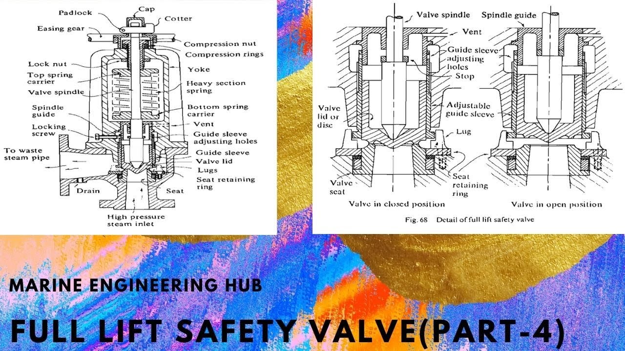
The terms full lift, high lift and low lift refer to the amount of travel the disc undergoes as it moves from its closed position to the position required to produce the certified discharge capacity, and how this affects the discharge capacity of the valve.
A full lift safety valve is one in which the disc lifts sufficiently, so that the curtain area no longer influences the discharge area. The discharge area, and therefore the capacity of the valve are subsequently determined by the bore area. This occurs when the disc lifts a distance of at least a quarter of the bore diameter. A full lift conventional safety valve is often the best choice for general steam applications.
The disc of a high lift safety valve lifts a distance of at least 1/12th of the bore diameter. This means that the curtain area, and ultimately the position of the disc, determines the discharge area. The discharge capacities of high lift valves tend to be significantly lower than those of full lift valves, and for a given discharge capacity, it is usually possible to select a full lift valve that has a nominal size several times smaller than a corresponding high lift valve, which usually incurs cost advantages.Furthermore, high lift valves tend to be used on compressible fluids where their action is more proportional.
In low lift valves, the disc only lifts a distance of 1/24th of the bore diameter. The discharge area is determined entirely by the position of the disc, and since the disc only lifts a small amount, the capacities tend to be much lower than those of full or high lift valves.
Except when safety valves are discharging, the only parts that are wetted by the process fluid are the inlet tract (nozzle) and the disc. Since safety valves operate infrequently under normal conditions, all other components can be manufactured from standard materials for most applications. There are however several exceptions, in which case, special materials have to be used, these include:
Cast steel -Commonly used on higher pressure valves (up to 40 bar g). Process type valves are usually made from a cast steel body with an austenitic full nozzle type construction.
For all safety valves, it is important that moving parts, particularly the spindle and guides are made from materials that will not easily degrade or corrode. As seats and discs are constantly in contact with the process fluid, they must be able to resist the effects of erosion and corrosion.
The spring is a critical element of the safety valve and must provide reliable performance within the required parameters. Standard safety valves will typically use carbon steel for moderate temperatures. Tungsten steel is used for higher temperature, non-corrosive applications, and stainless steel is used for corrosive or clean steam duty. For sour gas and high temperature applications, often special materials such as monel, hastelloy and ‘inconel’ are used.
A key option is the type of seating material used. Metal-to-metal seats, commonly made from stainless steel, are normally used for high temperature applications such as steam. Alternatively, resilient discs can be fixed to either or both of the seating surfaces where tighter shut-off is required, typically for gas or liquid applications. These inserts can be made from a number of different materials, but Viton, nitrile or EPDM are the most common. Soft seal inserts are not generally recommended for steam use.
Standard safety valves are generally fitted with an easing lever, which enables the valve to be lifted manually in order to ensure that it is operational at pressures in excess of 75% of set pressure. This is usually done as part of routine safety checks, or during maintenance to prevent seizing. The fitting of a lever is usually a requirement of national standards and insurance companies for steam and hot water applications. For example, the ASME Boiler and Pressure Vessel Code states that pressure relief valves must be fitted with a lever if they are to be used on air, water over 60°C, and steam.
A test gag (Figure 9.2.7) may be used to prevent the valve from opening at the set pressure during hydraulic testing when commissioning a system. Once tested, the gag screw is removed and replaced with a short blanking plug before the valve is placed in service.
The amount of fluid depends on the particular design of safety valve. If emission of this fluid into the atmosphere is acceptable, the spring housing may be vented to the atmosphere – an open bonnet. This is usually advantageous when the safety valve is used on high temperature fluids or for boiler applications as, otherwise, high temperatures can relax the spring, altering the set pressure of the valve. However, using an open bonnet exposes the valve spring and internals to environmental conditions, which can lead to damage and corrosion of the spring.
When the fluid must be completely contained by the safety valve (and the discharge system), it is necessary to use a closed bonnet, which is not vented to the atmosphere. This type of spring enclosure is almost universally used for small screwed valves and, it is becoming increasingly common on many valve ranges since, particularly on steam, discharge of the fluid could be hazardous to personnel.
Some safety valves, most commonly those used for water applications, incorporate a flexible diaphragm or bellows to isolate the safety valve spring and upper chamber from the process fluid, (see Figure 9.2.9).
Surface-controlled subsurface safety valves (SCSSVs) are critical components of well completions, preventing uncontrolled flow in the case of catastrophic damage to wellhead equipment. Fail-safe closure must be certain to ensure proper security of the well. However, this is not the only function in which it must be reliable—the valve must remain open to produce the well. Schlumberger surface controlled subsurface safety valves exceed all ISO 10432 and API Spec 14A requirements for pressure integrity, leakage acceptance criteria, and slam closure.
Through decades of innovation and experience, Schlumberger safety valve flapper systems are proven robust and reliable. The multizone dynamic seal technology for hydraulic actuation of subsurface safety valves is a further improvement in reliability performance when compared with traditional seal systems in the industry.
The multizone seal technology is currently available in the GeoGuard high-performance deepwater safety valves, which is validated to API Spec 14A V1 and V1-H.

The Department of Trade(DOT) limits this accumulation of pressure to 10% of the maximum allowable working pressure for the boiler. There are three types of safety valves used onboard.
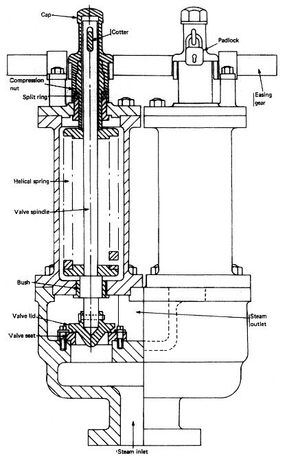
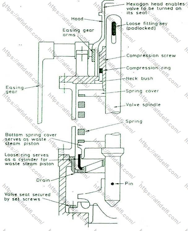
1 Improved high lift safety valve This valve increases their valve lift without increase in boiler pressure in two ways, one is the specially shaped valve seat, the other being to use the lower spring carrier in the fashion of a piston, which acted upon by the pressure of waste steam helps to compress the spring.
This valve consists of main & pilot control valves both being in direct communication with boiler pressure. The main advantage of this type of valve is that the main valve is kept closed by the boiler pressure acting upon it. As there is no spring to oppose this force, higher the boiler pressure greater the closing load. The pilot valve as is lifts due to rise in pressure inside boiler blanks off its ports leading to atmosphere & allows the steam pressure to build up & act upon the operating piston attached to the main valve spindle causing the main safety valve open. It has 4 times discharge capacity of ordinary safety valve.
The main advantage of using this valve is that the valve moves up in the guide sleeve, which prevents the waste steam pressure acting on top of the valve & a vent is provided to keep the space between the valve disc & spindle guide at atmospheric pressure. When the valve fully enters the guide sleeve, it causes some of the escaping steam to be deflected downwards by the bottom edge of the guide sleeve the resulting reaction setup assisting the waste steam pressure to lift the valve to its full open position, this together with the nozzle shaped inlet to the valve seat gives full flow conditions for the escaping steam.
There is a wide range of safety valves available to meet the many different applications and performance criteria demanded by different industries. Furthermore, national standards define many varying types of safety valve.
The ASME standard I and ASME standard VIII for boiler and pressure vessel applications and the ASME/ANSI PTC 25.3 standard for safety valves and relief valves provide the following definition. These standards set performance characteristics as well as defining the different types of safety valves that are used:
• ASME I valve -A safety relief valve conforming to the requirements of Section I of the ASME pressure vessel code for boiler applications which will open within 3% overpressure and close within 4%. It will usually feature two blowdown rings, and is identified by a National Board ‘V’ stamp.
• ASME VIII valve -A safety relief valve conforming to the requirements of Section VIII of the ASME pressure vessel code for pressure vessel applications which will open within 10% overpressure and close within 7%. Identified by a National Board ‘UV’ stamp.
• Full bore safety valve - A safety valve having no protrusions in the bore, and wherein the valve lifts to an extent sufficient for the minimum area at any section, at or below the seat, to become the controlling orifice.
• Conventional safety relief valve -The spring housing is vented to the discharge side, hence operational characteristics are directly affected by changes in the backpressure to the valve.
• Balanced safety relief valve -A balanced valve incorporates a means of minimising the effect of backpressure on the operational characteristics of the valve.
• Pilot operated pressure relief valve -The major relieving device is combined with, and is controlled by, a self-actuated auxiliary pressure relief device.
• Power-actuated safety relief valve -A pressure relief valve in which the major pressure relieving device is combined with, and controlled by, a device requiring an external source of energy.
• Standard safety valve - A valve which, following opening, reaches the degree of lift necessary for the mass flowrate to be discharged within a pressure rise of not more than 10%. (The valve is characterised by a pop type action and is sometimes known as high lift).
• Full lift (Vollhub) safety valve - A safety valve which, after commencement of lift, opens rapidly within a 5% pressure rise up to the full lift as limited by the design. The amount of lift up to the rapid opening (proportional range) shall not be more than 20%.
• Direct loaded safety valve - A safety valve in which the opening force underneath the valve disc is opposed by a closing force such as a spring or a weight.
• Proportional safety valve -A safety valve which opens more or less steadily in relation to the increase in pressure. Sudden opening within a 10% lift range will not occur without pressure increase. Following opening within a pressure of not more than 10%, these safety valves achieve the lift necessary for the mass flow to be discharged.
• Diaphragm safety valve - A direct loaded safety valve wherein linear moving and rotating elements and springs are protected against the effects of the fluid by a diaphragm.
• Bellows safety valve - A direct loaded safety valve wherein sliding and (partially or fully) rotating elements and springs are protected against the effects of the fluids by a bellows. The bellows may be of such a design that it compensates for influences of backpressure.
• Controlled safety valve -Consists of a main valve and a control device. It also includes direct acting safety valves with supplementary loading in which, until the set pressure is reached, an additional force increases the closing force.
• Safety valve -A safety valve which automatically, without the assistance of any energy other than that of the fluid concerned, discharges a quantity of the fluid so as to prevent a predetermined safe pressure being exceeded, and which is designed to re-close and prevent further flow of fluid after normal pressure conditions of service have been restored. Note; the valve can be characterised either by pop action (rapid opening) or by opening in proportion (not necessarily linear) to the increase in pressure over the set pressure.
• Direct loaded safety valve - A safety valve in which the loading due to the fluid pressure underneath the valve disc is opposed only by a direct mechanical loading device such as a weight, lever and weight, or a spring.
• Assisted safety valve -A safety valve which by means of a powered assistance mechanism, may additionally be lifted at a pressure lower than the set pressure and will, even in the event of a failure of the assistance mechanism, comply with all the requirements for safety valves given in the standard.
• Supplementary loaded safety valve -A safety valve that has, until the pressure at the inlet to the safety valve reaches the set pressure, an additional force, which increases the sealing force.
Note; this additional force (supplementary load), which may be provided by means of an extraneous power source, is reliably released when the pressure at the inlet of the safety valve reaches the set pressure. The amount of supplementary loading is so arranged that if such supplementary loading is not released, the safety valve will attain its certified discharge capacity at a pressure not greater than 1.1 times the maximum allowable pressure of the equipment to be protected.
• Pilot operated safety valve -A safety valve, the operation of which is initiated and controlled by the fluid discharged from a pilot valve, which is itself, a direct loaded safety valve subject to the requirement of the standard.
The terms full lift, high lift and low lift refer to the amount of travel the disc undergoes as it moves from its closed position to the position required to produce the certified discharge capacity, and how this affects the discharge capacity of the valve.
A full lift safety valve is one in which the disc lifts sufficiently, so that the curtain area no longer influences the discharge area. The discharge area, and therefore the capacity of the valve are subsequently determined by the bore area. This occurs when the disc lifts a distance of at least a quarter of the bore diameter. A full lift conventional safety valve is often the best choice for general steam applications.
The disc of a high lift safety valve lifts a distance of at least 1/12th of the bore diameter. This means that the curtain area, and ultimately the position of the disc, determines the discharge area. The discharge capacities of high lift valves tend to be significantly lower than those of full lift valves, and for a given discharge capacity, it is usually possible to select a full lift valve that has a nominal size several times smaller than a corresponding high lift valve, which usually incurs cost advantages.Furthermore, high lift valves tend to be used on compressible fluids where their action is more proportional.
In low lift valves, the disc only lifts a distance of 1/24th of the bore diameter. The discharge area is determined entirely by the position of the disc, and since the disc only lifts a small amount, the capacities tend to be much lower than those of full or high lift valves.
Except when safety valves are discharging, the only parts that are wetted by the process fluid are the inlet tract (nozzle) and the disc. Since safety valves operate infrequently under normal conditions, all other components can be manufactured from standard materials for most applications. There are however several exceptions, in which case, special materials have to be used, these include:
• Cast steel -Commonly used on higher pressure valves (up to 40 bar g). Process type valves are usually made from a cast steel body with an austenitic full nozzle type construction.
For all safety valves, it is important that moving parts, particularly the spindle and guides are made from materials that will not easily degrade or corrode. As seats and discs are constantly in contact with the process fluid, they must be able to resist the effects of erosion and corrosion.
The spring is a critical element of the safety valve and must provide reliable performance within the required parameters. Standard safety valves will typically use carbon steel for moderate temperatures. Tungsten steel is used for higher temperature, non-corrosive applications, and stainless steel is used for corrosive or clean steam duty. For sour gas and high temperature applications, often special materials such as monel, hastelloy and ‘inconel’ are used.
Type of boiler safety valve, marine auxiliary boiler and exhaust gas boiler setting of safety valve, accumulation pressure test, boiler safety valve set pressure, boiler safety valve working pressure , material used in construction of safety valve, marine boiler safety valve overhaul, boiler safety valve regulations.

(WIRE DRAWING– IT IS THE CONDITION IN WHICH A THIN FILM OF STEAM BLOWS ACROSS BETWEEN THE VALVE FACES CAUSING THE CUTTING OF THE VALVE FACES WHICH LEADS TO THE LOSS OF THE VALVE STEAM.)
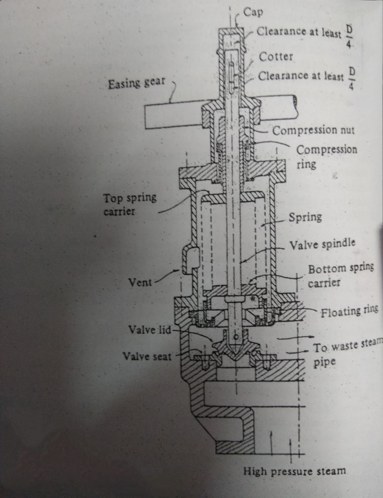
3.WHEN THE STEAM ACTS ON THE OPERATING PISTON IT CAUSES THE OPENING OF THE MAIN VALVE AGAINST THE SPRING PRESSURE. AS THE DIAMETER IS TWICE OF THE MAIN VALVE IT CAUSE THE D/4 LIFTING OF THE MAIN VALVE(i:e- FULL LIFT OF THE SAFETY VALVE).
A fire-tube boiler can be fitted with one or more safety valves on the top of its shell, with each set to open when the boiler reaches its design pressure. Noisolation valvesor restrictions should be integrated between the safety valve(s) and boiler. If the valves are not installed directly onto the boiler shell, the pipework connecting the valves to the boiler must be kept clear of blockagesand water, and this must be confirmed by periodic testing.
Once a safety valve opens, steam is discharged via the exhaust pipe. Exhaust pipes must be designed to encounter as few bends as possible, be as short as possible, to have no reduction in pipe section (no internal pipe diameter reduction), and should lead to asafe point of discharge(typically outside the boiler house).
Water must be drained from the safety valve or exhaust pipework via a drainpipe. Drainpipes may be connected to holes drilled into the lowest section of the exhaust pipework, or, directly to drain holes in the safety valve body; these drains are not to be confused with the blowdown ring locking bolt, if one is fitted.
Where two safety valves are fitted, it is common that one is set just belowthe boiler’s design pressure. It is vital that each safety valve permits the full flow of steam produced when the boiler is operating at maximum capacity i.e. when the boiler is producing the maximum amount of steam it can possibly produce. If safety valves are sized correctly, a boiler can be firing at full capacity without the steam pressure exceeding design limits (because the safety valve(s) relieves pressure at a faster rate than it is accumulated).
There are various types of safety valve, including high lift and improved high lift valves, which use the force of escaping steam to open a winged valve plug to achieve greater steam flow rates. In addition to this, some valves integrate a pistonat the bottom of the spring chamber. The piston has a larger surface area than the valve plug, which leads to the valve opening with a definitive ‘pop’ sound.
Some boiler safety valves include a blowdown ring. The blowdown ring can raise or lower the valve seat ring and is used to control the amount of blowdown through the valve. This ring is locked by a bolt that protrudes through the valve and into the adjusting ring segments.
Boiler safety valves should be fitted with an easing gear (looks like a handle), used, when necessary, to rapidly release boiler pressure. Easing gears can also be used for testing a safety valve, ensuring the spindle has freedom of movement and that the valve operating mechanism functions as intended. Easing gear testing is often not conducted due to operators having difficulty with the valves resealing, but this is generally only the case with valves that are not tested often enough. Actuating the easing gear several times is often all it takes to dislodge debris from the sealing area and allow the valve to seal again. For safe operation, the easing gear handle is usually connected via steel cables to an area neighbouring the boiler.
Like pressure gauges, all safety valves should be stripped, inspected, and calibrated, at least once a year; maintenance usually occurs during statutory inspections. Calibration of each valve should be conducted by a competent person, and any valve adjustment (including the blowdown ring) should be approved and sealed by the authorised inspector. After testing and calibration, all valves should be correctly marked, suitable certificates issued, and accurate records maintained.
An accumulation test can be conducted to ensure a safety valve can relieve over-pressure steam when the boiler burner is operating at maximum capacity. Accumulation testing of safety valves must be repeated after any alterations are made to the boiler e.g. replacement of a safety valve, fuel change, or changes to the control system. If, during an accumulation test, boiler pressure rises by more than 10% of its design pressure, the test must be aborted. Before the boiler is re-tested, amendments must be made to either the safety valve relieving capacity, thesafety valve exhaust pipework, or the boiler’s steaming capacity, to ensure the 10% limit is never exceeded.
Reliefand safetyvalves prevent equipment damage by relieving over-pressurisation of fluid systems. The main difference between a relief valve and a safety valve is the extent of opening at the set-point pressure.
A relief valve gradually opens as the inlet pressure increases above the set-point. A relief valve opens only as necessary to relieve the over-pressure condition. Relief valves are typically used for liquid systems.
A safety valve rapidly‘pops’ fully openas soon as the pressure setting is reached and will stay fully open until the pressure drops below the reset pressure. The reset pressure is lower than the actuating set-point pressure. The difference between the actuating pressure set-point, and the pressure at which the safety valve resets, is called blowdown. Safety valves are typically used for gas or vapour systems.
A safety relief valve may open fully, or proportionally, once the pressure setting is reached. SRVs may be used for any fluid system (gas, liquid, or vapour).

BOILER ARE TO BE FITTED WITH NOT LESS THAN 2 SAFETY VALVES EACH HAVING A MINIMUM INTERNAL DIAMETER OF 25MM. BUT THOSE HAVING HEATING SURFACE < 50 SQM. , MAY HAVE 1 SAFETY VALVE OF INTERNAL DIAMETER NOT LESS THAN 50MM.
BLOWDOWN:-IS THE DIFFERENCE B/W THE SET PRESSURE AND THE PRESSURE AT WHICH VALVE CLOSES AFTER RELEASING EXCESS PRESSURE. VALVE SHOULD BE SET TO LIFT AT 3% ABOVE DESIGNED PRESSURE AND BLOWDOWN % SHOULD BE 4%.
THEN ACCORING TO RULE THE BOILER SHOULD BE SET AT 3% I.E 15.45 BAR MAXIMUM. SINCE THERE ARE 2 SAFETY VALVES NORMALLY HENCE ONE CAN BE SET AT 15.2 WHILE LATER CAN BE SET AT 15.3 LIKEWISE I.E THEY WILL LIFT AT 15.2 AND 15.3 BAR IN SUCH A WAY THAT IT DONOT ACCUMULATE 16.5 I.E 1.5 BAR PRESSURE MORE IN BOILER FOR 15 MIN IN FIRE TUBE AND 7 MIN IN WATER TUBE.
Safety valves are fitted to protect the boiler from the effect of over pressure. At least two safety valves are fitted to each boiler steam drum, but if there is a super heater, another safety valve should be fitted on it.
The pressure setting of the superheater safety valve should be less that the designed pressure of the boiler, i.e. less than that of the steam drum safety valve, to ensure flow of steam through the superheater under blow off conditions. The pressure setting of one steam drum safety valve should be same as the design pressure of the boiler. The pressure setting of another safety valve should be 2-3 % more than the designed pressure of the boiler.
A lip is placed around the valve seat so that when the valve lid lifts, escaping steam is trapped in the annular space around the valve face, the resultant build–up of pressure acting upon the greater valve lid area causes the valve to lift sharply. This arrangement gives another advantage to close the valve cleanly and sharply with very little blow down effect.
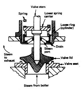
The improved high lift safety valve makes use of waste steam pressure to increase the valve lift; this is done by allowing the pressure to act upon the lower spring carrier which fits within a floating ring so forming in effect a piston. The pressure acts upon this piston causing it to move up, helping to compress the spring and so increasing the valve lift.
A cap is then fitted over the compression nut and the top of the valve spindle, a cotter is passed through and padlocked to prevent tampering by unauthorized person.
15. Valve Area (As) greater than (A) due to specific volume of steam increases with increases of temperature at constant pressure and more escape area is required to avoid accumulation of pressure.
To check the proper working condition of the boiler safety valve we carry out the “Hand trying out the Boiler Safety valve” at regular intervals. The safety valve is provided with the easing gear which manually lifts the safety valve and releases the excess pressure in the boiler. When the easing gear is pulled, the valve will be opened by hand to a full lift of ¼ D to release the boiler pressure. Before carrying out the process the boiler safety valve has to be drained.
Draining of the boiler safety valve is necessary as to prevent any build-up of water in the pipe line causing head of water to form over the valve lid so increasing the blow off pressure. So at regular intervals the boiler safety valve should be drained.
The waste steam pipe of the boiler safety valve should be well secured so that no load of the pipe is on the safety valve, which can be the cause of additional stress on the valve.
If it is found that the boiler safety relief valve is not lifting at the designed lifting pressure, manual pressure setting of the boiler safety valve has to be done for the proper and safe operation of the boiler. The adjustment can be carried out on this type of valve to give the desired discharge and blow down characteristic.
Slowly raise the boiler pressure and blow off the safety valves manually few times for thermal expansion and to reduce the thermal stress on the valves.
Raise the boiler steam pressure 2-3 % more than the designed pressure of the boiler, then stop firing and unscrew the first valve slowly, when it blows off at 2-3 % more than the designed pressure then note this opening and closing pressure of the valve and finally gag it.
Raise the boiler pressure at the designed pressure of the boiler and unscrew the 2nd valve, when it blows off at designed pressure then note this opening pressure and check the closing pressure also. Recheck the setting pressure and gag the valve.

All delivery charges are included in the final shopping basket and are dependent on the products Scottish Highlands & the Islands where additional shipping charges will apply.
Please note that not all products will incur an additional delivery charge to the Scottish Highlands & the Islands – this is based on the costs from the manufacturer, distributor or courier providing shipping on our behalf. If your delivery address is in the Scottish Highlands and Islands, a member of our helpline team will contact you prior to processing your order should an additional delivery charge apply.


 8613371530291