
improved high lift safety valve free sample

In order to ensure that the maximum allowable accumulation pressure of any system or apparatus protected by a safety valve is never exceeded, careful consideration of the safety valve’s position in the system has to be made. As there is such a wide range of applications, there is no absolute rule as to where the valve should be positioned and therefore, every application needs to be treated separately.
A common steam application for a safety valve is to protect process equipment supplied from a pressure reducing station. Two possible arrangements are shown in Figure 9.3.3.
The safety valve can be fitted within the pressure reducing station itself, that is, before the downstream stop valve, as in Figure 9.3.3 (a), or further downstream, nearer the apparatus as in Figure 9.3.3 (b). Fitting the safety valve before the downstream stop valve has the following advantages:
• The safety valve can be tested in-line by shutting down the downstream stop valve without the chance of downstream apparatus being over pressurised, should the safety valve fail under test.
• When setting the PRV under no-load conditions, the operation of the safety valve can be observed, as this condition is most likely to cause ‘simmer’. If this should occur, the PRV pressure can be adjusted to below the safety valve reseat pressure.
Indeed, a separate safety valve may have to be fitted on the inlet to each downstream piece of apparatus, when the PRV supplies several such pieces of apparatus.
• If supplying one piece of apparatus, which has a MAWP pressure less than the PRV supply pressure, the apparatus must be fitted with a safety valve, preferably close-coupled to its steam inlet connection.
• If a PRV is supplying more than one apparatus and the MAWP of any item is less than the PRV supply pressure, either the PRV station must be fitted with a safety valve set at the lowest possible MAWP of the connected apparatus, or each item of affected apparatus must be fitted with a safety valve.
• The safety valve must be located so that the pressure cannot accumulate in the apparatus viaanother route, for example, from a separate steam line or a bypass line.
It could be argued that every installation deserves special consideration when it comes to safety, but the following applications and situations are a little unusual and worth considering:
• Fire - Any pressure vessel should be protected from overpressure in the event of fire. Although a safety valve mounted for operational protection may also offer protection under fire conditions,such cases require special consideration, which is beyond the scope of this text.
• Exothermic applications - These must be fitted with a safety valve close-coupled to the apparatus steam inlet or the body direct. No alternative applies.
• Safety valves used as warning devices - Sometimes, safety valves are fitted to systems as warning devices. They are not required to relieve fault loads but to warn of pressures increasing above normal working pressures for operational reasons only. In these instances, safety valves are set at the warning pressure and only need to be of minimum size. If there is any danger of systems fitted with such a safety valve exceeding their maximum allowable working pressure, they must be protected by additional safety valves in the usual way.
In order to illustrate the importance of the positioning of a safety valve, consider an automatic pump trap (see Block 14) used to remove condensate from a heating vessel. The automatic pump trap (APT), incorporates a mechanical type pump, which uses the motive force of steam to pump the condensate through the return system. The position of the safety valve will depend on the MAWP of the APT and its required motive inlet pressure.
This arrangement is suitable if the pump-trap motive pressure is less than 1.6 bar g (safety valve set pressure of 2 bar g less 0.3 bar blowdown and a 0.1 bar shut-off margin). Since the MAWP of both the APT and the vessel are greater than the safety valve set pressure, a single safety valve would provide suitable protection for the system.
However, if the pump-trap motive pressure had to be greater than 1.6 bar g, the APT supply would have to be taken from the high pressure side of the PRV, and reduced to a more appropriate pressure, but still less than the 4.5 bar g MAWP of the APT. The arrangement shown in Figure 9.3.5 would be suitable in this situation.
Here, two separate PRV stations are used each with its own safety valve. If the APT internals failed and steam at 4 bar g passed through the APT and into the vessel, safety valve ‘A’ would relieve this pressure and protect the vessel. Safety valve ‘B’ would not lift as the pressure in the APT is still acceptable and below its set pressure.
It should be noted that safety valve ‘A’ is positioned on the downstream side of the temperature control valve; this is done for both safety and operational reasons:
Operation - There is less chance of safety valve ‘A’ simmering during operation in this position,as the pressure is typically lower after the control valve than before it.
Also, note that if the MAWP of the pump-trap were greater than the pressure upstream of PRV ‘A’, it would be permissible to omit safety valve ‘B’ from the system, but safety valve ‘A’ must be sized to take into account the total fault flow through PRV ‘B’ as well as through PRV ‘A’.
A pharmaceutical factory has twelve jacketed pans on the same production floor, all rated with the same MAWP. Where would the safety valve be positioned?
One solution would be to install a safety valve on the inlet to each pan (Figure 9.3.6). In this instance, each safety valve would have to be sized to pass the entire load, in case the PRV failed open whilst the other eleven pans were shut down.
If additional apparatus with a lower MAWP than the pans (for example, a shell and tube heat exchanger) were to be included in the system, it would be necessary to fit an additional safety valve. This safety valve would be set to an appropriate lower set pressure and sized to pass the fault flow through the temperature control valve (see Figure 9.3.8).

Surface-controlled subsurface safety valves (SCSSVs) are critical components of well completions, preventing uncontrolled flow in the case of catastrophic damage to wellhead equipment. Fail-safe closure must be certain to ensure proper security of the well. However, this is not the only function in which it must be reliable—the valve must remain open to produce the well. Schlumberger surface controlled subsurface safety valves exceed all ISO 10432 and API Spec 14A requirements for pressure integrity, leakage acceptance criteria, and slam closure.
Through decades of innovation and experience, Schlumberger safety valve flapper systems are proven robust and reliable. The multizone dynamic seal technology for hydraulic actuation of subsurface safety valves is a further improvement in reliability performance when compared with traditional seal systems in the industry.
The multizone seal technology is currently available in the GeoGuard high-performance deepwater safety valves, which is validated to API Spec 14A V1 and V1-H.
Boiler Safety Valves protect the boiler from over pressurisation. As per the requirements, at least two safety valves should be fitted to the boiler and both are mounted on a common manifold with a single connection to the boiler. Boiler with super heater, normally three safety valves are fitted; two to the boiler drum and one to the superheater. The superheater must be set to lift first to ensure a flow of steam through the superheater.
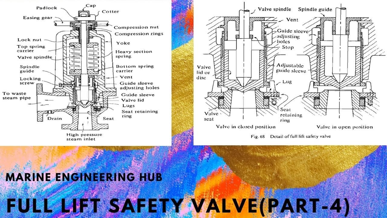
The sketch shown is improve high lift safety valve . The are usually mounted 2 Nos. on a single chest. Valve , seat , spindle , compression screw and bush are made of non-corroded metal and valve chest is made of cast steel.
The special shaped valve and seat deflect steam toward the lips on the valve and increase valve lift.This action also achieves the valve to lift and shut smartly at the blow off pressure. It is set to open at 3 % above working pressure. The lift of valve is one twelfth of the valve diameter.
A ported guide plate fitting adequately guide the spindle itself and allow the waste steam to the under side of the piston with pressure and gives increased valve lift. Waste steam pressure also keeps the floating cylinder in place while the piston moves. So floating cylinder seizure risk is reduced.
A drainpipe is fitted to the lowest part of the valve chest on the waste steam discharge side and lead to clearly drain, no valve or cock fitted through its length. This drain is important to be checked regularly. If it is choked, there is a possibility of overload to valve , due to hydraulic head and damage results by water hammer.
Check valve and seat for wear, cavity corrosion , pitting and any fault. They must be ground in properly not to excess maker’s limited dimensions and clearances.
The accumulating pressure test is done to limit the excessive pressure rising in boiler while the safety valve is open, cause further compression of spring due to increased loading. .
The test is carried out, on the new boilers or new safety valves , under full firing conditions, with feed water and steam main stop valve is closed. The test is continued for as long as the water in the boiler permits but it need15 minutes for a tank type boiler and 7 minutes for a water tube boiler. With the safety valves operating, accumulation must not exceed 10% of the working pressure.

UNITED STATES GEORGE HALL CLARK, or cAME mGE, MASsAcriUsETTs, AssIG oE. "To CROSBY STEAM GAGE & VALVE ooMr NY, F BOSTON, MASSACHUSETTS, A CORPORA- TION 0E MAssAcHqsETTs.
Be it knoyvn that I, GEORGE HALL CLARK, a citizen of the United States of America and resident of Cambridge, in the county of Middlesex and State of Massachusetts, have invented new and useful Improvements in Safety-Valves, of which the following is a specification.
My invention relates to safety valves for steam boilers, and consists"in improvements applicable to safety valves of the prevalent huddling chamber type, such as the commercially known Crosby standard stationary valve. The object of my invention is to in-- crease the maximum lift of such a valve, without sensibly affecting the behavior of the valve at low values of lift, either when opening or closing.
Figure 1 is a vertical cross section of a safety valve showing its well known characteristic parts; and I Fig. 2 is a fragmentary side elevation of that portion of the valve structure which contains the member chiefly characteristic of my improvement.
In the drawing the following named parts are comprised in a safety valve of the general character indicated A is the valve disk, -B the base on which is formed valve seat S. The valve disk and base are shaped to form the annular pressure chamberor huddling chamber D which lies between the seat S.
n The well-known action of"safety valves of. this type is as follows: When pressure in. the boiler-reaches the point at which the "alve is set, the disk A lifts slightly, steam passes through the seat aperture thus produced into the chamber D from which there are twooutlets, one through the lip aperture PAjTENT-OFFlCE. A
The aggregate of thareas of the lip aperture E and that over the ring C is such that pressure is built up in the chamber D and the valve pops, receiving a sudden, relatively large increase in lift. The extent of thislift ,depends"on the total upward pressure on the disk including the area in the chamber D and tlfe downward force exerted by the spring. Assuming"the. valve to be blowlng freely and to be of suflioient size to reduce the boiler pressure gradually, the
equilib ium is disturbed as pressure 1s reduced and the lift decreases. The discharge area at the seat S which may be termed the seat vent is directly proportional to the lift, while the discharge area from the chamber D is the aggregate of the area of openings from the chamber D when the valve is closed and the incrementin area brought about byv each increase in lift.
As the lip diameter is greater than the seat diameter the total effective area at the lip increases faster per unit of lift than the total area at. the seat. In short, the lip vent is initially larger than and increases faster than the seat vent. As the valve disk the ratio 5 is decreasing very rapidly. This ratio is the factor which determines the pressure in. the chamber D and the consequent lifting force on the disk. For this reason I provide means to make this factor or ratio approach more nearly to unity at V the higher lifts so that the valve may experience consequently an increase in lift and capacity. But it must be borne in mind that conditions at the lower lifts must be left undisturbed go that the designed factors for controlling the valve at those values of lift may not be appreciably altered.
In order to obtain increased lifts at the vide means by which in effect the outlet area at the lip or lip vent is made to approximate progressively to equality to the outlet area at the seat, leaving the controllin conditions unchanged at low lifts. 1
Heturning now. to the drawing: I attachto or form integrally with the adjusting ring C an annular screen G which lies around the valvedisk adjacent to the \lip vent. This screen is perforated with a number of circular apertures H which are so proportioned and positioned that at low lifts there is ample passage for"steam escaping from the lip vent at E; that is to say, at low lifts substantially none of the solid screen material is opposed to the free discharge of steam. But as the disk A lifts higher and the disk lip a rises, it comes into opposition to greater and greater extent with the solid material of which the screen G is composed; or speaking conversely, the width of the apertures H measured along horizontal chords becomes less and less.
This progressive opposition of more and more screen area to the discharge of the steam as the valve lifts, obstructs the efilux of steam, and has substantially the same effect as would be produced by an actual constriction of the vent area E.. This results in effect in makingthe area ratio Q approach unity at the higher lifts. Relatively to the lip vent the area of the series of holes H decreases progressively as the lift increases, but this area is sufficiently large and The result of employment of this improvement" is to increase the maximum lift of a valve from its original value by from fifty to seventy-five per cent.
1. In a safety valve of the character described, the combination of a valve disk and a base arranged, to provide a lip-vent between them, and means to obstruct the lipvent at relatively high valve lift-positions. ,2. Ina safety valve of the character described, the combination of a valve disk and a base arranged toprovide a lip-vent between them, and means to obstruct progressively the lip-vent at relatively high valve lift-positions. 1
. 3. In a"safety valve of the character described, the combination of a valve disk and a base arranged to provide a lip-vent between them, and a screen adjacent to the lip-vent and disposed to obstruct the same at relatively high valve-lift positions. i
4. In a safety valve of the character described, the combination -of a valve disk and a base arranged to providea lip-vent be- .tWeen"" them, and a screen adjacent to the lipvent and disposed"to obstruct the same progressively at relatively high valve-lift positlons.
scribed, the combination of a valve disk and a base arranged to provide a lip-vent between them,an adjusting ring, and a screen carried on the ring, adjacent to the lip-vent and disposed to obstruct the same at relatively high valve-lift "positions.
tween them, an adjusting ring, and a screen carried on the ring, adjacent to the lip-vent and disposed to obstruct the same progressively at relatively high valve-lift positions.
7. In a safety valve of the character described, the combination of a valve disk and a base arranged to provide a lip-vent between them, an adjusting ring, and"an apertured screen carried on the ring, adjacent to the lip vent and disposed to obstruct the same at relatively high lift positions, the free area of the screen apertures being in the aggregate greater than the seat vent area at the maximum, of the latter.

A safety valve is a valve that acts as a fail-safe. An example of safety valve is a pressure relief valve (PRV), which automatically releases a substance from a boiler, pressure vessel, or other system, when the pressure or temperature exceeds preset limits. Pilot-operated relief valves are a specialized type of pressure safety valve. A leak tight, lower cost, single emergency use option would be a rupture disk.
Safety valves were first developed for use on steam boilers during the Industrial Revolution. Early boilers operating without them were prone to explosion unless carefully operated.
Vacuum safety valves (or combined pressure/vacuum safety valves) are used to prevent a tank from collapsing while it is being emptied, or when cold rinse water is used after hot CIP (clean-in-place) or SIP (sterilization-in-place) procedures. When sizing a vacuum safety valve, the calculation method is not defined in any norm, particularly in the hot CIP / cold water scenario, but some manufacturers

Earlier, marine boilers were primarily installed on a ship for the propulsion plant, which used to run on steam (steam engine). Today, the steam generated by the boiler is utilized in various systems in the engine room, including heating of fuel for the main engine. Considering the importance of marine boilers and the risks involved with its operation on ships, there has been constant development in the industry to enhance boiler safety on board. Some even consider it one of the “deadliest” machinery systems on board.
Scalding: Scalding is a type of burn caused by high-temperature steam. Steam burn is one of the most common accidents seafarers experience on board. It is said that 8 out of 10 seamen, who work with the steam system, have experienced scalding (major or minor) in their careers at least once.
Hot Surface: The boiler and the associated pipes, valves, and auxiliaries have a very hot surface as they carry steam to different parts of the ship. A direct skin contact with any of the exposed surface will lead to severe burn.
Other Risks: Other risks such as high pressurized parts, handling harmful chemicals, moving machinery etc. are also associated with operating marine boilers.
Needless to say, safety is a critical aspect when operating a high or even a low-pressure boiler on a ship and therefore different marine boiler devices are provided.
Boiler Safety System and Instruments: A modern marine boiler is fitted with several safety devices for the protection of the operator. For easy understanding, let us divide these instruments/devices as per the system they are fitted in –
Steam Safety System: The steam system in the boiler is a high pressure, high-temperature area. To safeguard the operator and the boiler itself, it is fitted with the following safety features:
Safety Valve: Boiler safety valve is an extremely important safety equipment fitted on the steam drum of the boiler. As per SOLAS chapter II-1, every steam boiler and every un-fired steam generator shall be provided with not less than 2 safety valves of adequate capacity. However, with regards to the output or any other feature of a boiler or un-fired steam generator, the administration may permit only one safety valve to be fitted if adequate protection against overpressure is thereby satisfactorily provided.
Usually, an improved high lift is one of the most popular types of safety valves used on a ship. They are set to lift at the blow-off pressure and shut when the pressure reduces to the safe limit. They are set to open at 3 % above working pressure. The lift of valve is one-twelfth of the valve diameter.
Easing Gear: The easing gear is attached to the boiler safety valve. Every individual safety valve is provided with its own easing gear, which is a pulley and wire arrangement (connected to the lever of the safety valve) with an accessible handle at the lower operating boiler platform. It is used to lift the boiler safety valve in case of an emergency (without getting near to the safety valve) and to regularly test the operation of the safety valves.
Steam Pressure Alarm and cutout: An audio-visual alarm is also provided for the steam pressure system to remind the operator about the steam pressure. Once the alarm activates and the pressure continues to rise (or decrease), the cut-out will get activated and it will shut off the fuel burner. The cutout functioning is different and independent of the automation which operates the burner. The low-pressure cutout has an option to override it, but the high-pressure cutout will stop the burner and should never be overridden in any case
Water Safety System: The water system is a high-temperature system and the level and quality of the water inside the water drum plays a crucial role in the safe operation of the boiler. Following are the equipment/system fitted on the water side of the marine boiler:
Low / high water level alarm and cutout: The boiler water drum is fitted with a level sensor, which will continuously monitor the level of water inside the drum. A full drum will carry over the water or will have no space to generate steam, thus reducing the efficiency of the boiler; whereas low or no water level in the drum will lead to over-heating of tubes and can lead to fire or meltdown of the complete boiler.
The low/ high water level provides an early warning to the operator for taking appropriate action to manage the water level inside the boiler water drum.
Too low water level alarm and shut down: The initial warning provided by the above arrangement (low/high water level alarm), may not be sufficient for the operator as there can be a major leak in the tubes, leading to a reduction in the water level. A secondary safety is therefore provided i.e. Too low water level alarm and shut down, which will stop the burner firing to control the overheating of the boiler internal parts.
Water level indicators: The boiler is fitted with multiple water level indicators to make it easy for the operator to see the water drum level and ensure operational safety of the boiler.
Salinity Sensor: The boiler drum is fitted with a salinity sensor, which continuously monitors the dissolved solids content in the water. If the solid (e.g. salt) content exceeds the set value, it trips the boiler to ensure the tubes and boiler internals does not get affected due to the contamination. The operator should either blow down the boiler and feed fresh water to the drum to eliminate the cause which is resulting in high salinity (for e.g. leakage in the condenser)
Fuel Safety System: The boiler is provided with heavy or marine gas fuel oil for generating the heat in the furnace. To ensure the fuel system is operating efficiently, it is fitted with the following boiler safety features:
Low / high fuel oil temperature alarm: Modern marine boilers are meant to operate in different grades of fuel due to the port / ECA regulations for minimizing the air pollution from the ship. The oil temperature is an important factor as it controls the viscosity of the fuel which is directly related to atomization and efficient combustion inside the furnace. If the fuel temperature is not at its set value (which will vary for different grades), the alarm will sound. The operator must stop the alarm and the oil temperature should be brought to normal before restarting the boiler.
Smoke Density alarm: With more stringent rules coming up for environmental protection, the boiler exhaust is fitted with a smoke density sensor which detects the post-combustion product, especially during starting of a boiler and at low loads. If the smoke density is higher than the required value, it will sound an alarm to which the operator needs to check the combustion of the boiler
Operational Safety: Automation, alarms, and warnings have made the life of seafarers on ships a lot easier than what it used to be in terms of boiler safety. However, professional engineers rarely depend on them and always rely on the best practice for efficiently running the machinery.
Lagging: Once the steam comes out of the boiler via main steam stop valve, it is supplied to several systems via pipes and distribution valves. A proper lagging on the pipes and valves will ensure the boiler need not run extra as the steam loss will be contained. Also, it ensures the safety of ship staff from surface burns.
Maintenance: On-time maintenance such as testing of safety valve, cleaning of boiler tubes etc. will result in safe and efficient working of the marine boiler.


 8613371530291