
lever type safety valve manufacturer

Distributor of hydraulic press safety, quick opening safety, rotary and safety valves. Amerigear®, Boston Gear®, Carlisle®, DeMag®, Desch® and IMI Norgren®, pneumatic, double action, quick release and flow control valves also provided. Repair and preventative maintenance services are offered. Value added services such as custom barcoding, CAD capabilities, OEM assembly, plant surveys and third party logistics are also available. Serves the metal processing, metal service center, paper mill and paper converting, canning, grinding, commercial laundry, marine, oil and gas and material handling industries. Vendor managed inventory (VMI) programs available. Kanban delivery.
Safety Relief Valve automatically releases a substance from a boiler, pressure vessel, or other system when the pressure or temperature exceeds preset limits.
The lever is pivoted at one end. A weight on the lever is set at a distance from the pivot point so the fulcrum is sufficient to overcome the pressure in the boiler.
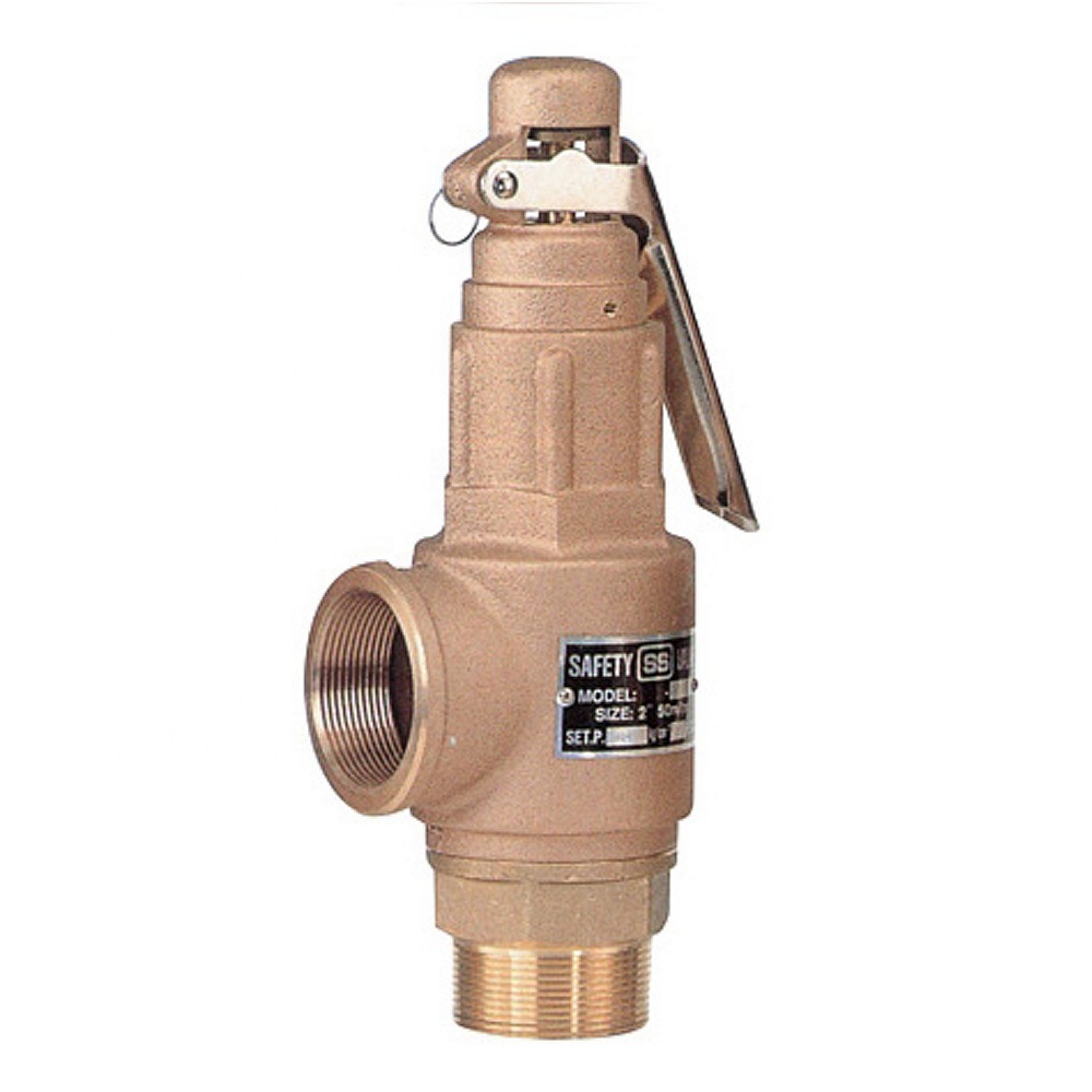
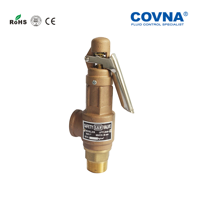
The Brass Safety Valve is characterized by regulating of pressure in valve rising and blowing-out when actuated and is the smallest and lightest valve. And also can be used in non-corrosive gases(Air,Oxygen,Nitrogen etc.) steam and liquids,such as water and oil.

There is a wide range of safety valves available to meet the many different applications and performance criteria demanded by different industries. Furthermore, national standards define many varying types of safety valve.
The ASME standard I and ASME standard VIII for boiler and pressure vessel applications and the ASME/ANSI PTC 25.3 standard for safety valves and relief valves provide the following definition. These standards set performance characteristics as well as defining the different types of safety valves that are used:
ASME I valve - A safety relief valve conforming to the requirements of Section I of the ASME pressure vessel code for boiler applications which will open within 3% overpressure and close within 4%. It will usually feature two blowdown rings, and is identified by a National Board ‘V’ stamp.
ASME VIII valve- A safety relief valve conforming to the requirements of Section VIII of the ASME pressure vessel code for pressure vessel applications which will open within 10% overpressure and close within 7%. Identified by a National Board ‘UV’ stamp.
Full bore safety valve - A safety valve having no protrusions in the bore, and wherein the valve lifts to an extent sufficient for the minimum area at any section, at or below the seat, to become the controlling orifice.
Conventional safety relief valve -The spring housing is vented to the discharge side, hence operational characteristics are directly affected by changes in the backpressure to the valve.
Balanced safety relief valve -A balanced valve incorporates a means of minimising the effect of backpressure on the operational characteristics of the valve.
Pilot operated pressure relief valve -The major relieving device is combined with, and is controlled by, a self-actuated auxiliary pressure relief device.
Power-actuated safety relief valve - A pressure relief valve in which the major pressure relieving device is combined with, and controlled by, a device requiring an external source of energy.
Standard safety valve - A valve which, following opening, reaches the degree of lift necessary for the mass flowrate to be discharged within a pressure rise of not more than 10%. (The valve is characterised by a pop type action and is sometimes known as high lift).
Full lift (Vollhub) safety valve -A safety valve which, after commencement of lift, opens rapidly within a 5% pressure rise up to the full lift as limited by the design. The amount of lift up to the rapid opening (proportional range) shall not be more than 20%.
Direct loaded safety valve -A safety valve in which the opening force underneath the valve disc is opposed by a closing force such as a spring or a weight.
Proportional safety valve - A safety valve which opens more or less steadily in relation to the increase in pressure. Sudden opening within a 10% lift range will not occur without pressure increase. Following opening within a pressure of not more than 10%, these safety valves achieve the lift necessary for the mass flow to be discharged.
Diaphragm safety valve -A direct loaded safety valve wherein linear moving and rotating elements and springs are protected against the effects of the fluid by a diaphragm
Bellows safety valve - A direct loaded safety valve wherein sliding and (partially or fully) rotating elements and springs are protected against the effects of the fluids by a bellows. The bellows may be of such a design that it compensates for influences of backpressure.
Controlled safety valve - Consists of a main valve and a control device. It also includes direct acting safety valves with supplementary loading in which, until the set pressure is reached, an additional force increases the closing force.
Safety valve - A safety valve which automatically, without the assistance of any energy other than that of the fluid concerned, discharges a quantity of the fluid so as to prevent a predetermined safe pressure being exceeded, and which is designed to re-close and prevent further flow of fluid after normal pressure conditions of service have been restored. Note; the valve can be characterised either by pop action (rapid opening) or by opening in proportion (not necessarily linear) to the increase in pressure over the set pressure.
Direct loaded safety valve -A safety valve in which the loading due to the fluid pressure underneath the valve disc is opposed only by a direct mechanical loading device such as a weight, lever and weight, or a spring.
Assisted safety valve -A safety valve which by means of a powered assistance mechanism, may additionally be lifted at a pressure lower than the set pressure and will, even in the event of a failure of the assistance mechanism, comply with all the requirements for safety valves given in the standard.
Supplementary loaded safety valve - A safety valve that has, until the pressure at the inlet to the safety valve reaches the set pressure, an additional force, which increases the sealing force.
Note; this additional force (supplementary load), which may be provided by means of an extraneous power source, is reliably released when the pressure at the inlet of the safety valve reaches the set pressure. The amount of supplementary loading is so arranged that if such supplementary loading is not released, the safety valve will attain its certified discharge capacity at a pressure not greater than 1.1 times the maximum allowable pressure of the equipment to be protected.
Pilot operated safety valve -A safety valve, the operation of which is initiated and controlled by the fluid discharged from a pilot valve, which is itself, a direct loaded safety valve subject to the requirement of the standard.
The common characteristic shared between the definitions of conventional safety valves in the different standards, is that their operational characteristics are affected by any backpressure in the discharge system. It is important to note that the total backpressure is generated from two components; superimposed backpressure and the built-up backpressure:
Subsequently, in a conventional safety valve, only the superimposed backpressure will affect the opening characteristic and set value, but the combined backpressure will alter the blowdown characteristic and re-seat value.
The ASME/ANSI standard makes the further classification that conventional valves have a spring housing that is vented to the discharge side of the valve. If the spring housing is vented to the atmosphere, any superimposed backpressure will still affect the operational characteristics. Thiscan be seen from Figure 9.2.1, which shows schematic diagrams of valves whose spring housings are vented to the discharge side of the valve and to the atmosphere.
By considering the forces acting on the disc (with area AD), it can be seen that the required opening force (equivalent to the product of inlet pressure (PV) and the nozzle area (AN)) is the sum of the spring force (FS) and the force due to the backpressure (PB) acting on the top and bottom of the disc. In the case of a spring housing vented to the discharge side of the valve (an ASME conventional safety relief valve, see Figure 9.2.1 (a)), the required opening force is:
In both cases, if a significant superimposed backpressure exists, its effects on the set pressure need to be considered when designing a safety valve system.
Once the valve starts to open, the effects of built-up backpressure also have to be taken into account. For a conventional safety valve with the spring housing vented to the discharge side of the valve, see Figure 9.2.1 (a), the effect of built-up backpressure can be determined by considering Equation 9.2.1 and by noting that once the valve starts to open, the inlet pressure is the sum of the set pressure, PS, and the overpressure, PO.
Balanced safety valves are those that incorporate a means of eliminating the effects of backpressure. There are two basic designs that can be used to achieve this:
Although there are several variations of the piston valve, they generally consist of a piston type disc whose movement is constrained by a vented guide. The area of the top face of the piston, AP, and the nozzle seat area, AN, are designed to be equal. This means that the effective area of both the top and bottom surfaces of the disc exposed to the backpressure are equal, and therefore any additional forces are balanced. In addition, the spring bonnet is vented such that the top face of the piston is subjected to atmospheric pressure, as shown in Figure 9.2.2.
The bellows arrangement prevents backpressure acting on the upper side of the disc within the area of the bellows. The disc area extending beyond the bellows and the opposing disc area are equal, and so the forces acting on the disc are balanced, and the backpressure has little effect on the valve opening pressure.
Bellows failure is an important concern when using a bellows balanced safety valve, as this may affect the set pressure and capacity of the valve. It is important, therefore, that there is some mechanism for detecting any uncharacteristic fluid flow through the bellows vents. In addition, some bellows balanced safety valves include an auxiliary piston that is used to overcome the effects of backpressure in the case of bellows failure. This type of safety valve is usually only used on critical applications in the oil and petrochemical industries.
Since balanced pressure relief valves are typically more expensive than their unbalanced counterparts, they are commonly only used where high pressure manifolds are unavoidable, or in critical applications where a very precise set pressure or blowdown is required.
This type of safety valve uses the flowing medium itself, through a pilot valve, to apply the closing force on the safety valve disc. The pilot valve is itself a small safety valve.
The diaphragm type is typically only available for low pressure applications and it produces a proportional type action, characteristic of relief valves used in liquid systems. They are therefore of little use in steam systems, consequently, they will not be considered in this text.
The piston type valve consists of a main valve, which uses a piston shaped closing device (or obturator), and an external pilot valve. Figure 9.2.4 shows a diagram of a typical piston type, pilot operated safety valve.
The piston and seating arrangement incorporated in the main valve is designed so that the bottom area of the piston, exposed to the inlet fluid, is less than the area of the top of the piston. As both ends of the piston are exposed to the fluid at the same pressure, this means that under normal system operating conditions, the closing force, resulting from the larger top area, is greater than the inlet force. The resultant downward force therefore holds the piston firmly on its seat.
If the inlet pressure were to rise, the net closing force on the piston also increases, ensuring that a tight shut-off is continually maintained. However, when the inlet pressure reaches the set pressure, the pilot valve will pop open to release the fluid pressure above the piston. With much less fluid pressure acting on the upper surface of the piston, the inlet pressure generates a net upwards force and the piston will leave its seat. This causes the main valve to pop open, allowing the process fluid to be discharged.
When the inlet pressure has been sufficiently reduced, the pilot valve will reclose, preventing the further release of fluid from the top of the piston, thereby re-establishing the net downward force, and causing the piston to reseat.
Pilot operated safety valves offer good overpressure and blowdown performance (a blowdown of 2% is attainable). For this reason, they are used where a narrow margin is required between the set pressure and the system operating pressure. Pilot operated valves are also available in much larger sizes, making them the preferred type of safety valve for larger capacities.
One of the main concerns with pilot operated safety valves is that the small bore, pilot connecting pipes are susceptible to blockage by foreign matter, or due to the collection of condensate in these pipes. This can lead to the failure of the valve, either in the open or closed position, depending on where the blockage occurs.
The terms full lift, high lift and low lift refer to the amount of travel the disc undergoes as it moves from its closed position to the position required to produce the certified discharge capacity, and how this affects the discharge capacity of the valve.
A full lift safety valve is one in which the disc lifts sufficiently, so that the curtain area no longer influences the discharge area. The discharge area, and therefore the capacity of the valve are subsequently determined by the bore area. This occurs when the disc lifts a distance of at least a quarter of the bore diameter. A full lift conventional safety valve is often the best choice for general steam applications.
The disc of a high lift safety valve lifts a distance of at least 1/12th of the bore diameter. This means that the curtain area, and ultimately the position of the disc, determines the discharge area. The discharge capacities of high lift valves tend to be significantly lower than those of full lift valves, and for a given discharge capacity, it is usually possible to select a full lift valve that has a nominal size several times smaller than a corresponding high lift valve, which usually incurs cost advantages.Furthermore, high lift valves tend to be used on compressible fluids where their action is more proportional.
In low lift valves, the disc only lifts a distance of 1/24th of the bore diameter. The discharge area is determined entirely by the position of the disc, and since the disc only lifts a small amount, the capacities tend to be much lower than those of full or high lift valves.
Except when safety valves are discharging, the only parts that are wetted by the process fluid are the inlet tract (nozzle) and the disc. Since safety valves operate infrequently under normal conditions, all other components can be manufactured from standard materials for most applications. There are however several exceptions, in which case, special materials have to be used, these include:
Cast steel -Commonly used on higher pressure valves (up to 40 bar g). Process type valves are usually made from a cast steel body with an austenitic full nozzle type construction.
For all safety valves, it is important that moving parts, particularly the spindle and guides are made from materials that will not easily degrade or corrode. As seats and discs are constantly in contact with the process fluid, they must be able to resist the effects of erosion and corrosion.
The spring is a critical element of the safety valve and must provide reliable performance within the required parameters. Standard safety valves will typically use carbon steel for moderate temperatures. Tungsten steel is used for higher temperature, non-corrosive applications, and stainless steel is used for corrosive or clean steam duty. For sour gas and high temperature applications, often special materials such as monel, hastelloy and ‘inconel’ are used.
A key option is the type of seating material used. Metal-to-metal seats, commonly made from stainless steel, are normally used for high temperature applications such as steam. Alternatively, resilient discs can be fixed to either or both of the seating surfaces where tighter shut-off is required, typically for gas or liquid applications. These inserts can be made from a number of different materials, but Viton, nitrile or EPDM are the most common. Soft seal inserts are not generally recommended for steam use.
Standard safety valves are generally fitted with an easing lever, which enables the valve to be lifted manually in order to ensure that it is operational at pressures in excess of 75% of set pressure. This is usually done as part of routine safety checks, or during maintenance to prevent seizing. The fitting of a lever is usually a requirement of national standards and insurance companies for steam and hot water applications. For example, the ASME Boiler and Pressure Vessel Code states that pressure relief valves must be fitted with a lever if they are to be used on air, water over 60°C, and steam.
A standard or open lever is the simplest type of lever available. It is typically used on applications where a small amount of leakage of the fluid to the atmosphere is acceptable, such as on steam and air systems, (see Figure 9.2.5 (a)).
Where it is not acceptable for the media to escape, a packed lever must be used. This uses a packed gland seal to ensure that the fluid is contained within the cap, (see Figure 9.2.5 (b)).
For service where a lever is not required, a cap can be used to simply protect the adjustment screw. If used in conjunction with a gasket, it can be used to prevent emissions to the atmosphere, (see Figure 9.2.6).
A test gag (Figure 9.2.7) may be used to prevent the valve from opening at the set pressure during hydraulic testing when commissioning a system. Once tested, the gag screw is removed and replaced with a short blanking plug before the valve is placed in service.
The amount of fluid depends on the particular design of safety valve. If emission of this fluid into the atmosphere is acceptable, the spring housing may be vented to the atmosphere – an open bonnet. This is usually advantageous when the safety valve is used on high temperature fluids or for boiler applications as, otherwise, high temperatures can relax the spring, altering the set pressure of the valve. However, using an open bonnet exposes the valve spring and internals to environmental conditions, which can lead to damage and corrosion of the spring.
When the fluid must be completely contained by the safety valve (and the discharge system), it is necessary to use a closed bonnet, which is not vented to the atmosphere. This type of spring enclosure is almost universally used for small screwed valves and, it is becoming increasingly common on many valve ranges since, particularly on steam, discharge of the fluid could be hazardous to personnel.
Some safety valves, most commonly those used for water applications, incorporate a flexible diaphragm or bellows to isolate the safety valve spring and upper chamber from the process fluid, (see Figure 9.2.9).
Searching for tools to control the flow of your piping system? Explore one of the largest featured collections of products and discover a range of wholesale lever type safety valve on Alibaba.com. When you search for lever type safety valve and related items, you will be able to find many types of lever type safety valve varying in size, shape, use, and quality, all at prices in which are highly reasonable!
There are many uses of valves - mainly controlling the flow of fluids and pressure. Some examples include regulating water for irrigation, industrial uses for controlling processes, and residential piping systems. Magnetic valves like those using the solenoid, are often used in a range of industrial processes. Whereas backflow preventers are often used in residential and commercial buildings to ensure the safety and hygiene of the water supplies. Whether you are designing a regulation system for irrigation or merely looking for a new replacement, you will be able to find whatever type of lever type safety valve that you need. Our products vary from check valves to pressure reducing valves, ball valves, butterfly valves, thermostatic mixing valves, and a lot more.

Searching for tools to control the flow of your piping system? Explore one of the largest featured collections of products and discover a range of wholesale lever safety valve on Alibaba.com. When you search for lever safety valve and related items, you will be able to find many types of lever safety valve varying in size, shape, use, and quality, all at prices in which are highly reasonable!
There are many uses of valves - mainly controlling the flow of fluids and pressure. Some examples include regulating water for irrigation, industrial uses for controlling processes, and residential piping systems. Magnetic valves like those using the solenoid, are often used in a range of industrial processes. Whereas backflow preventers are often used in residential and commercial buildings to ensure the safety and hygiene of the water supplies. Whether you are designing a regulation system for irrigation or merely looking for a new replacement, you will be able to find whatever type of lever safety valve that you need. Our products vary from check valves to pressure reducing valves, ball valves, butterfly valves, thermostatic mixing valves, and a lot more.
1 Piece Ball Valve1 Piece Cast Iron Screwed Ball Valve1 Piece Flanged Ball Valve1 Piece Screwed Ball Valve2 Piece Ball valve2 Piece Cast Steel Ball Valve2 Piece Flanged Ball Valve2 Piece Forged Steel Ball Valve2 Piece Screwed Ball Valve3 Piece Ball Valve3 Piece Cast Iron Ball Valve3 Piece Cast Steel Ball Valve3 Piece Flanged Ball Valve3 Piece Forged Steel Ball Valve3 Piece Reduced Port Ball Valve3 Piece Screwed Ball Valve3 Way Converging and Diverging Control Valve3 Way Plug Valve3 Way Pneumatic Diaphragm Control ValveAir ValveAlloy 20 2 Piece Ball ValveAlloy 20 2 Piece Screwed Ball ValveAlloy 20 3 Piece Ball ValveAlloy 20 3 Piece Screwed Ball ValveAlloy 20 Ball ValveAlloy 20 Dual Plate Lug Type Check ValveAlloy 20 Floating Ball ValveAlloy 20 Swing Check ValveAlloy 20 Trunnion Mounted Ball ValveAlloy 20 ValvesAlloy 20 Wafer Butterfly ValveAlloy Butterfly ValveAlloy Check valveAlloy Dual Plate Wafer Check ValveAlloy Flanged Gate ValveAlloy Flanged Globe ValveAlloy Gate ValveAlloy Gate ValvesAlloy Globe ValvesAlloy Lug Butterfly ValveAlloy Plug ValveAlloy Pressure Seal Globe ValveAluminium Bronze 3 Piece Ball ValveAluminium Bronze Ball ValveAluminium Bronze Butterfly ValveAluminium Bronze Check ValveAluminium Bronze Floating Ball ValveAluminium Bronze Gate ValveAluminium Bronze Lug Butterfly ValveAluminium Bronze Swing Check ValveAluminium Bronze Triple offset Lug Butterfly ValveAluminium Bronze Trunnion Ball ValveAluminium Bronze valvesAluminium Bronze Wafer Butterfly ValveAluminium Dual Plate Wafer Check ValveAluminum Bronze Globe ValveAngle Globe ValveANSI Gate ValveANSI Globe ValveAPI Aluminium Bronze Triple offset Lug Butterfly ValveAPI Gate ValveAPI Globe ValveAustenitic Steel Big Size Ball ValveAustenitic Steel ValvesAWWA Butterfly ValveAWWA Gate ValveAWWA Non Rising Stem Gate ValveAWWA OS&Y Gate ValveAWWA StrainerAWWA Wafer Butterfly ValveAWWA Y StrainerBalancing ValveBall Float Steam TrapBall ValveBellow Seal Globe ValveBi Directional Knife Gate ValveBimetallic Steam TrapBlock and Bleed valveBrass Ball ValveBrass Ball ValvesBrass Check ValvesBrass Flanged Ball ValveBrass Flanged Gate ValveBrass Flanged Globe ValveBrass Gate ValveBrass Gate ValvesBrass Globe ValveBrass Globe ValvesBrass Safety ValveBrass Swing Check ValveBrass ValveBrass Vertical Check ValveBrass Y StrainerBronze Butterfly ValveBronze Check ValveBronze Flanged Gate ValveBronze Flanged Globe ValveBronze Floating Ball ValveBronze Gate ValveBronze Gate ValvesBronze Globe ValveBronze Globe ValvesBronze Swing Check ValveBronze ValveBronze Wafer Butterfly ValveBronze Wafer Check ValveBS Cast Iron Gate valveBS Cast Steel Gate ValveBS Ductile Iron Gate ValveBS Globe ValveBS Non Rising Stem Gate ValveBS NRS Carbon Steel Gate ValveBS NRS Cast Iron Gate ValveBS NRS Ductile Iron Gate ValveBS Rising Stem Gate ValveBS Soft Seat Gate ValveBS Stainless Steel Gate ValveButterfly ValveCarbon Steel Bellow Seal Globe ValveCast Floating Ball ValveCast Iron And Cast Steel Ball ValveCast Iron Diaphragm ValveCasting Trunnion Ball Valvecheck valveConnection Lift Plug ValveControl ValveCryogenic Ball ValveCryogenic Check ValveCryogenic Emergency Cut off ValveCryogenic Gate ValveCryogenic Globe ValveCryogenic Long Stem Globe ValveCryogenic Pneumatic Actuated Globe ValveCryogenic Short Stem Globe ValveCryogenic Steam Jacket Globe ValveCryogenic ValveDiaphragm ValveDIN Globe ValveDIN Non Rising Stem Ductile Iron Gate ValveDIN Non Rising Stem Gate ValveDIN NRS Cast Iron Gate ValveDIN Rising Stem Cast Iron Gate ValveDIN Rising Stem Ductile Iron Gate ValveDIN Rising Stem Gate ValveDIN Soft Seat Gate ValveDirect Acting Pressure Reducing ValveDouble Block and Bleed Ball ValveDouble Disc Gate ValveDouble Eccentric Butterfly ValveDouble Offset Butterfly ValveDouble Orifice Air Release ValveDouble Orifice Kinetic Air ValveDual Plate Lug Check ValveDual Plate Wafer Check ValveDuctile Iron Diaphragm ValveDuplex 1B 3 PC Ball ValveDuplex 3 Piece Ball ValveDuplex Basket StrainerDuplex Butterfly ValveDuplex Check ValveDuplex Dual Plate Lug Type Check ValveDuplex Dual Plate Wafer Check ValveDuplex Floating Ball ValveDuplex Gate ValveDuplex Globe ValveDuplex High Pressure Ball ValveDuplex Lug Type Butterfly ValveDuplex Steel Ball ValveDuplex steel ValveDuplex Swing Check ValveDuplex Top Entry Ball ValveDuplex Trunnion Mounted Ball ValveDuplex Wafer Butterfly ValveEccentric Plug ValveElectric 3 Way Control ValveElectric Actuated 2 Piece Ball ValveElectric Actuated 2 Piece Flanged Ball ValveElectric Actuated 2 Piece Screwed Ball ValveElectric Actuated Ball ValveElectric Actuated Butterfly ValveElectric Actuated Flanged Ball ValveElectric Actuated Floating Forged Ball ValveElectric Actuated Gate ValveElectric Actuated Globe Control ValveElectric Actuated Globe ValveElectric Actuated High Pressure Ball ValvesElectric Actuated High Pressure Direct Mounting Ball ValvesElectric Actuated Lug Butterfly ValveElectric Actuated Metal-Seated Trunnion-Mounted Forged Ball ValveElectric Actuated Three Piece Ball ValveElectric Actuated Three Way Ball ValveElectric Actuated Trunnion-Mounted Casting Ball ValveElectric Actuated ValvesElectric Actuated Wafer Butterfly ValveElectric Cage Type Control ValveElectric Control ValveElectric Double Seat Control ValveElectric O-type Shut-off Control ValveElectric Single Seat Control ValveF22/Alloy Steel Pressure Seal Globe ValveF317L Gate ValveF317L Globe ValveF317L ValvesF321 Gate ValveF321 Globe ValveF321 ValvesF347 3 Piece Ball ValveF347 Ball ValveF347 Butterfly ValveF347 Check ValveF347 Dual Plate Lug Type Check ValveF347 Dual Plate Wafer Check ValveF347 Floating Ball ValveF347 Gate ValveF347 Globe ValveF347 Lug Type Butterfly ValveF347 Swing Check ValveF347 Trunnion Mounted Ball ValveF347 ValvesF347 Wafer Butterfly ValveF44 Gate ValveF44 Globe valvesF44 ValvesF51 Super Duplex Ball ValveF53/F55 Super Duplex Globe ValveFeed Water Control ValveFlanged Butterfly ValveFlanged Knife gate ValveFloat Control ValveFloating Ball ValveFluorine Lined Single Seat Control ValveFoot ValveForged Cryogenic Trunnion Ball ValveForged Floating Ball ValveForged Steel Ball ValveForged Steel Gate ValveForged Steel Globe ValveForged Steel Swing Check ValveForged Trunnion Ball ValveFull Lift Pressure Safety ValveFull Lift Safety ValveFully Welded Ball ValveGate ValveGlobe ValveHastelloy Ball ValveHastelloy C276 2 Piece Flanged Ball ValveHastelloy C276 2 Piece Screwed Ball ValveHastelloy C276 3 Piece Screwed Ball ValveHastelloy C276/B3 3 Piece Ball ValveHastelloy C276/B3 Butterfly ValveHastelloy C276/B3 Dual Plate Lug Type Check ValveHastelloy C276/B3 Dual Plate Wafer Check ValveHastelloy C276/B3 Floating Ball ValveHastelloy C276/B3 Gate ValvesHastelloy C276/B3 Globe ValveHastelloy C276/B3 Lug Butterfly ValveHastelloy C276/B3 Swing Check valveHastelloy C276/B3 Trunnion Mounted Ball ValveHastelloy C276/B3 ValvesHastelloy C276/B3 Wafer Butterfly ValveHastelloy Check ValveHeavy Duty Investment Casting Ball ValveHigh Performance Lug Butterfly ValveHigh Performance Wafer Butterfly ValveIncoloy 2 Piece Ball ValveIncoloy 3 Piece Ball ValveIncoloy Gate ValveIncoloy Globe ValveIncoloy ValvesInconel 2 Piece Ball ValveInconel 3 Piece Ball ValveInconel Ball ValveInconel Butterfly ValveInconel Check ValveInconel Dual Plate Lug Type Check ValveInconel Dual Plate Wafer Check ValveInconel Floating Ball ValveInconel Gate ValveInconel Globe ValveInconel Lug Butterfly ValveInconel safety relief valveInconel Swing Check ValveInconel Trunnion Mounted Ball ValveInconel ValveInconel Wafer Butterfly ValveInverted Bucket Steam TrapInvestment Casting Ball ValveJacketed Ball ValveJacketed Plug ValveKnife Gate ValveLift Check valveLow Lift Pressure Safety ValveLow Lift Safety ValveLubricated Plug valveLug Butterfly ValveMonel 2 Piece Ball ValveMonel 3 Piece Ball ValveMonel 400 2 Piece Flanged Ball ValveMonel 400 ValvesMonel Ball ValveMonel Butterfly ValveMonel Check ValveMonel Dual Plate Lug Check ValveMonel Dual Plate Wafer Check ValveMonel Floating Ball ValveMonel Forged Trunnion Mounted Ball ValveMonel Gate ValveMonel Globe ValveMonel High Pressure Ball ValveMonel Lug Type Butterfly ValveMonel Swing Check ValveMonel Top Entry Ball ValveMonel Trunnion Mounted Ball ValveMonel ValvesMonel Wafer Butterfly ValveNeedle valveNon Slam Swing Check ValveNon-Lubricated Sleeved Plug ValveNon-Rising Stem Gate ValveNon-Slam Swing Check ValveOrbit Plug ValvePilot Operated Pressure Reducing ValvePilot Operated ValvePressure Relief ValvePiston ValvePlug ValvePlunger ValvePneumatic Actuated 2 Piece Ball ValvePneumatic Actuated 2 Piece Flanged Ball ValvePneumatic Actuated Ball ValvePneumatic Actuated Butterfly ValvePneumatic Actuated Flanged Ball ValvePneumatic Actuated Flanged Butterfly ValvePneumatic Actuated Gate ValvePneumatic Actuated Globe type Control ValvePneumatic Actuated Lug Butterfly ValvePneumatic Actuated Three Piece Ball valvePneumatic Actuated Three Way Ball valvePneumatic Actuated Three Way Heavy Duty Ball ValvePneumatic Actuated Two Piece Ball ValvePneumatic Actuated ValvesPneumatic Actuated Wafer Butterfly ValvePneumatic Angle Control ValvePneumatic Angle Seat Control ValvePneumatic Angle Type High Pressure Regulating Control ValvePneumatic Bi Directional Knife Gate valvePneumatic Cage Control ValvePneumatic Control ValvePneumatic Double Seat Control ValvePneumatic Flow Control ValvePneumatic Knife Gate ValvePneumatic Metal Seat Flanged Ball ValvePneumatic Single Seat Globe Control ValvePneumatic Sleeve Type Control ValvePneumatic Three piece Ball ValvePneumatic Three Piece Flanged Ball ValvePneumatic Three Way Ball ValvePneumatic Three Way Flanged Ball ValvePneumatic Trunnion Casting Ball ValvePneumatic Trunnion Forged Ball ValvePneumatic Trunnion Forged Metal Seat Ball ValvePneumatic Unidirectional Knife Gate ValvePressure Reducing ValvePressure Safety ValvePressure Seal Gate ValvePressure Seal Globe ValvePressure Seal Swing Check ValveRotary Airlock ValveSafety ValveSimplex Basket StrainersSingle Orifice Air ValveSingle Plate Wafer Check ValveSlab Gate ValveSlurry Knife Gate ValveSoft Seal Gate ValveSpeciality ValveSS304 Bellow Seal Globe ValveSS316 Bellow Seal Globe ValveSS316L Gate ValveSS316L Lug Butterfly ValveSS316L Wafer Butterfly ValveSteam Pressure Reducing ValveSteam Safety ValveSteam TrapStrainersSuction DiffuserSuper Duplex 2 Piece Ball ValveSuper Duplex 3 Piece Ball ValveSuper Duplex 5A Flanged Gate ValveSuper Duplex 5A Globe ValveSuper Duplex 5A Swing Check ValveSuper Duplex Ball ValveSuper Duplex Butterfly ValveSuper Duplex Check ValveSuper Duplex Dual Plate Lug Type Check ValveSuper Duplex Dual Plate Wafer Check ValveSuper Duplex Floating Ball ValveSuper Duplex Gate ValveSuper Duplex Gate ValvesSuper Duplex Globe ValveSuper Duplex High Pressure Ball ValveSuper Duplex Knife Gate ValveSuper Duplex Lug Butterfly ValveSuper Duplex Pressure Reducing ValveSuper Duplex Top Entry Ball ValveSuper Duplex Trunnion Mounted Ball ValveSuper Duplex ValvesSuper Duplex Wafer Butterfly ValveSurge Anticipator ValveSwing Check ValveThermal Safety ValveThermodynamic Steam TrapThermostatic Steam TrapThree Piece Flanged Ball ValveThree Way Ball ValveThrough Conduit Knife Gate ValveTilting Disc Check ValveTitanium 3 Piece Ball ValveTitanium Ball ValveTitanium Butterfly ValveTitanium Check ValveTitanium Dual Plate Lug Type Check ValveTitanium Dual Plate Wafer Check ValveTitanium Floating Ball ValveTitanium Forged Trunnion Mounted Ball ValveTitanium Gate ValveTitanium Globe ValveTitanium Gr.2 2pc Flanged Ball ValveTitanium Gr.2 3pc Ball ValveTitanium Gr.5 2pc Flanged Ball ValveTitanium Gr.5 3pc Ball ValveTitanium Lug Butterfly ValveTitanium Swing Check ValveTitanium Trunnion Mounted Ball ValveTitanium valvesTitanium Wafer Butterfly ValveTop Entry Ball ValveTriple Duty ValveTriple Eccentric Butterfly ValveTriple Offset Butterfly ValveTrunnion Ball ValveTwin Seal Plug ValveUL/FM Approved ValvesUnidirectional Knife Gate ValveWafer Butterfly ValveWater Pressure Reducing ValveY StrainerY Type Globe ValveZirconium Floating Ball ValveZirconium Gate ValveZirconium Globe ValveZirconium Valves

Manufacturer of a wide range of products which include boiler safety valve, safety valve-pop type, pressure safety valve, spring loaded safety valve, safety relief valve and ibr safety valve.
ConnectionThreaded and Flanged EndsWe are the manufacturer, Supplier, and Exporter of Boiler Safety Valve from Chennai -India to Globally. These Safety Valves are Used to release the excess pressure inside the Boiler, High-Pressure Tanks, nd Vessels. So that Pressure can be maintained uniformly. we are manufacturer of valves like: Pressure Relief Valves, Safety relief Valves, Vacuum Relief Valve, Pressure cum vacuum relief valve, Breather valves.
Certificate-ApprovalISO, IBR, IRS, ATEX, TUV, BV, SGSWe are the manufacturer, supplier, and exporter of Safety Valves from Chennai-India to Globally. Used for controlling excess pressures, their precision construction standards make them extensively used in equipment like pressure vessels, pipelines & reactors.We have good infrastructure facility for EXPORT
LeverPlain and Packed LeverBEEKAY brand Safety Valve, Safety Relief Valve, pressure Safety Valves are manufactured by LEVEL AND FLOW CONTROL ENGINEERS in India. Pressure Safety Valve can safeguard the tanks, vessels, boilers, and other capital equipments. when the pressure is esceed the limit valve will open automatically and release the excess pressure.we are expecting enquiry and orders from all over the world.
Accumulation0 to 10%LFCE Spring Loaded Safety Valve, Safety Relief Valves and Pressure Relief Valves are high performance and cost effective. Based on client request we can ready to supply valves with 0 to 5% accumulation and blowdown.Valve size : 1/4" to 12"
Country of OrginIndiaBEEKAY brand Safety Valve, Safety Relief Valve are manufactured by Level and Flow Control Engineers in INDIA. Valves are 100% safe and accuracy for Set pressure and Re-set pressures. Valves are mounted on pipelines, tanks, vessels and reactors to safeguard the capital equipments.We have already exported our range of products to all over the world like UAE, Middle East, Germany, Italay, Australlia, Malysia, Thailand, Indonesia, Philipines, Burunei, Srilanka, Pakistan, Netherland and many more
Flange Ratings150, 300, 600, 900, 1500 lbs RatingsLFCE Manufacturing, supplying, Exporting IBR Certified Safety Valves for Boilers, Deareators, LP, HP Heaters, Condensate Tanks and Vessels. We can able to supply the valves size from 25NB to 300NB and the Pressure Rating 150 lbs to 1500 lbs
We are expecting enquiry and orders from all over the world. Our valves and range of products are well exported to UAE, MIddle East, Thailand, Indonesia, Mayanmar, Vietnam, Srilanka, Malaysia, Singapore, Philipines, Australlia, Netherland, Italy, UAE, South African Countires.
Country of OriginMade in IndiaLFCE manufacturing, supplying, EXPORTING Safety Valve, Pressure Relief Valves with Lever and Plain types.We can able to supply CS, SS, DSS, SDSS, Alloy Steel grade of Materials with Max. of Pressure of 150 barValve size from 15NB to 200NBWe are expecting good enquiry and orders from all over the globe.
Rust ResistanceYesLFCE manufacturing and supplying Beekay brand Brass Safety Valves, Safety Relief Valves, Pressure Relief Valves fo the pressure vessels and Air Receivers. When the pressure is exceed the limit then the valve will open automatically and safeguard the capital equipments.Our brand Beekay is well known in the global market. Already we exported our range of products to all over the world :- UAE, Middle East, South Africa, Zimbawe, Zambia, Kenya, Oman, Saudi Arabia, Thailand, Indonesia, Philipines, Burunei, Srilanka, Pakistan, Hongkong, Netherland, Italay and many more
Flange StandardsANSI, BS, DIN, JS, IS, ASMELFCE manufacturing and EXPORTING Low Pressure, Medium Pressure, High Pressure Safety Valves, Safety Relief Valves for the Process Industries and Hydro Carbon Projects.Our Valves are manufactured and tested as per API StandardsWe are expecting enquiry/orders from all over the world.
Because a safety valve is often the last device to prevent catastrophic failure under pressure conditions, it is important that the valve works at all times i.e. it must be 100% reliable.
Safety valves should be installed wherever the maximum allowable working pressure of a system or pressure containing vessel is likely to be exceeded, in particular under fault conditions due to the failure of another piece of equipment in the system.
The term “Safety Valve” and “Relief Valve” are generic terms to describe a variety of pressure relief devices. A wide range is available based on the application and required performance criteria. The different designs are required to meet numerous national standards.
The images below show the devastating results of a failed Safety valve (due to poor maintenace) or ones which have been incorrectly sized, installed or maintained.
A spring-loaded pressure relief valve which is designed to open to relieve excess pressure and to reclose and prevent the further flow of fluid after normal conditions have been restored. It is characterised by a rapid-opening "pop" action or by opening in a manner generally proportional to the increase in pressure over the opening pressure. It may be used for either compressible or incompressible fluids, depending on design, adjustment, or application.
Relief valve - A pressure relief device actuated by inlet static pressure having a gradual lift generally proportional to the increase in pressure over opening pressure.
Safety relief valve - A pressure relief valve characterised by rapid opening or pop action, or by opening in proportion to the increase in pressure over the opening pressure, depending on the application, and which may be used either for liquid or compressible fluid.
Safety valve - A valve which automatically, without the assistance of any energy other than that of the fluid concerned, discharges a quantity of the fluid so as to prevent a predetermined safe pressure being exceeded, and which is designed to re-close and prevent further flow of fluid after normal pressure conditions of service have been restored.
The images below show a standard Relief valve and a standard Safety valve from a well-known UK manufacturer. Each manufacturer does things slightly differently however all of the basic components and principles of operation are the same. As described previously, a safety valve differs from a relief valve in that it opens rapidly once the set pressure has been reached. For the same inlet size and with the valve in the closed position, the surface area that the pressure on the inlet side will see is the same. When the set pressure is reached and the valve starts to open, the disk on a Safety valve is larger (see the diagrams below) and hence the same pressure then sees a much larger surface area and consequently the force increases greatly causing the valve to open quickly and hence the characteristic pop action.
The image below shows the above Safety valves and Relief valves dismantled. The disk diameter on the 1" (DN25) Safety valve is only 7mm larger than on the Relief valve which doesnt sound like much, but when you calculate the areas it is an increase of 36%.
This diagram represents a Safety valve in its very simplest form. The force acting on the inlet side of the disk is acting against the force applied by the spring plus the force applied by the back pressure on the top of the disk.
The valve remains closed when(PI x Ab) < Fs + (PB x At), is in equilibrium when(PI x Ab) = Fs + (PB x At) and opens when(PI x Ab) > Fs + (PB x At) were PI = Inlet pressure, PB = Back pressure, At = Top of disk area, Ab = Bottom of disk area. Things to notice from this design are that if PB is variable and quite large relative to PI, then this will cause the pressure at which the valve opens to vary which is undesirable. The following two designs (Fig 3 & Fig 4) are available that eliminate the effect of back pressure on the set pressure.
The bellows prevents backpressure acting on the top side of the disk. In relation to the piston there is no top side within the main body of the valve hence again the back pressure cannot affect the set pressure. Bellows failure is an important concern in critical applications where a very precise set pressure is required. In these cases some mechanism to detect a leak of process medium out of the top vent would be implemented. Piston designs are not usually found in conventional Safety valves but are more common in Pilot Operated Safety valves.
API 520 Practice Guidelines: a conventional design should not typically be used when the built-up backpressure is greater than 10% of the set pressure at 10% over pressure. European standard EN ISO 4126: the built-up backpressure should be limited to 10% of the set pressure when the valve is discharging at the certified capacity.
Overpressure is the percentage over the set pressure by which the valve is fully open. The blowdown is the percentage below the set pressure by which the valve is fully closed.
The basic elements of the design are right angle pattern valve body, inlet can be either a full nozzle or a semi-nozzle type. With a full nozzle design has the “wetted” inlet tract formed from one piece (as per figure 6) with the seat integrated into the top of the nozzle. The internal bore of the nozzle and the disc is the only part of the valve that is exposed to the process fluid with the valve in the closed position. A semi-nozzle design consists of a seating ring fitted into the body.The disc is held onto the seat by the stem, with the downward force coming from the compression on the spring mounted in the bonnet. The amount of compression on the spring is adjusted by the spring adjuster under the cap.
Unless bellows or diaphragm sealing is used, process fluid will enter the spring housing (or bonnet). The amount of fluid depends on the particular design of safety valve. If emission of this fluid into the atmosphere is acceptable, the spring housing may be vented to the atmosphere - an open bonnet. This is usually advantageous when the safety valve is used on high temperature fluids or for boiler applications as, otherwise, high temperatures can relax the spring, altering the set pressure of the valve. However, using an open bonnet exposes the valve spring and internals to environmental conditions, which can lead to damage and corrosion of the spring.
When the fluid must be completely contained by the safety valve (and the discharge system), it is necessary to use a closed bonnet, which is not vented to the atmosphere. This type of spring enclosure is almost universally used for small screwed valves and, it is becoming increasingly common on many valve ranges since, particularly on steam, discharge of the fluid could be hazardous to personnel.
A lifting mechanism is recommended to test for correct valve operation at all times where corrosion, caking, or any deposit could prevent the opening operation.
Foreign particles can lodge under the seat of the valve when it discharges. The lifting lever allows you to lift the valve and flush the obstruction. Pressure relief valves for Section VIII require a lift lever on all air, steam, and hot water valves used at temperatures over 60 degC. Typically used where periodic testing of the valve in location is desired to assure its operation. With an Open lifting lever design, when the valve discharges, fluid media will escape into the atmosphere around the open lifting lever assembly. If this is not desirable or when back pressure is present you would select a Packed Lifting Lever design.
As described above, this type is selected where leakage of the media to the atmosphere during valve discharge or during back pressure would be un-desirable. A packed lever design is a completely sealed assembly.
Under certain circumstances i.e. under the start-up conditions of a plant or to pressure test the system in a controlled environment, it may be required that the valve is prevented from opening.This is achieved by screwing the bolt (shown on the wire) into the cap which screws down onto the stem and prevents it lifting. Obviously it is important that test gags are removed prior to placing the valve into service.
The bellows is designed to cover the same area on the back of the disc equal to the seat area hence the back pressure will have no effect on the set pressure. See the previous section “Basic Safety Valve Principles”. Bellows also protects the spindle, spindle guide and spring from the process medium.
A disc is held against the nozzle by a spring, which is contained in a cast bonnet. The spring is adjusted by a compression screw to permit the calibration of opening or set pressure. An adjustable nozzle ring, threaded onto the nozzle, controls the geometry of the fluid exit control chamber (also known as a huddling chamber). The control chamber (huddling chamber) geometry is very important in controlling valve opening and closing pressures and stability of operation. The nozzle ring is locked into position by a ring pin assembly as shown in Figure 15 below.
Under normal system operation the valve remains in the closed position because the spring force (Fs) is greater than the system pressure acting on the internal nozzle seating area (PA). If system pressure increases to a point when these forces are equal, then the set pressure is reached. The disc lifts and fluid flows through the valve. When pressure in the system returns to a safe level, the valve closes.
Just prior to reaching set point, the pressure relief valve leaks system fluid into the huddling chamber. The fluid now acts on a larger area of the disc inside the huddling chamber (PAh), causing the valve to experience an instantaneous increase in the opening force. Refer to the figure 16 above to see relationship between Nozzle Area (A) and the Huddling Chamber Area (Ah). System pressure acting on the larger area will suddenly open the safety relief valve at a rapid rate.
Although the opening is rapid and dramatic, the valve does not open fully at set point. The system pressure must increase above set point to open the valve to its full lift and capacity position. Maximum lift and certified flow rates will be achieved within the allowable limits (overpressure) established by various codes and standards. All pressure relief ales are allowed an overpressure allowance to reach full rated flow. The allowable over pressure can vary from 10% to 21% on unfired vessels and systems, depending on the sizing basis, number of valves, and whether a fire condition is encountered.
Once the valve has controlled the pressure excursion, system pressure will start to reduce. Since the huddling chamber area is now controlling the exit fluid flow, system pressure must reduce below the set point before the spring force is able to close the valve. The difference between the set pressure and the closing pressure is called blowdown, and is usually expressed as a percentage of set pressure. The typical blowdown can vary from 7% to 10%, the industry standard.
The nozzle ring adjustment changes the shape and volume of the huddling chamber, and its position will affect both the opening and the closing characteristics of the valve. When the nozzle ring is adjusted to its top position, the huddling chamber is restricted to its maximum. The valve will usually pop very distinctly with a minimum simmer (leakage before opening), but the blowdown will increase. When the nozzle ring is lowered to its lowest position, minimal restriction to the huddling chamber occurs. At this position, simmer increases and the blowdown decreases. The final ring position is somewhere between these two extremes to provide optimal performance.
On liquid service, a different dynamic situation exists. Liquids do not expand when flowing across orifices, and a small amount of fluid flow across the nozzle will produces a large local pressure drop at the nozzle orifice. This local pressure drop causes the spring to reclose the valve if the fluid flow is minimal. Liquids leaking into the huddling chamber can quickly drain out by gravity and prevent fluid pressure from building up in the secondary area of the huddling chamber. Liquid relief valves are thus susceptible to a phenomenon called chatter, especially at low fluid flow rates. Chatter is the rapid opening and closing of the pressure relief valve and is always destructive.
Because of the difference in the characteristics of gases and liquids, some valve designs require a special liquid trim in order to meet ASME Code Section VIII performance criteria of full rated liquid flow at 10% overpressure. With liquids since no visible or audible pop is heard at set point, the set pressure is defined as the pressure when the first heavy flow occurs (a pencil sized steady stream of water that remains unbroken for approximately one inch).
Manufacturers usually state their recommended testing procedure and testing intervals in their Installation, Operating and Maintenance Instructions (IOM). Typically, they recommend a manual test every 3 or 6 months (assuming it has a lifting lever) and a set pressure test every 12 months. It is sensible to incorporate these into your maintenance plan so they are not missed. Sometimes your insurance company may require them to be tested even more regularly than this i.e. every 6 months. Testing in most cases involves removing them from your system and having them recertified in an approved workshop.
If you have a system that is shut down for annual maintenance then this is an ideal time to remove your Safety valves and have them inspected and recertified.
For systems that can only be off for short periods of time, it is sensible to keep a spare valve to swap over and then the removed valve can be inspected and recertified.
For systems that cannot be shut down, you will need to use a changeover valve which allows you to swap between Safety valves allowing one to be removed for inspection and testing.
For larger Safety valves on systems that run continuously, you may consider using in-situ testing. This method does have some limitations however since you cannot visually inspect the inside of the valve, but it will tell you if the valve is opening at the correct set pressure.
(a) A valve passing (leaking) on the outlet side when the valve is supposed to be closed. This can happen to valves of any age (new or old) and occurs if debris contained in the medium passes through the valve at a point when the valve lifts, and the debris either traps or damages the internals of the valve. On soft seated valves, hard particles may embed themselves in the soft material causing re-sealing issues. If your valve has a lifting lever and it is safe to do so, then it is worth lifting the handle for a few seconds which will hopefully clear any debris allowing the valve to reseal correctly. If this isn’t an option or it doesn’t cure the problem, then the valve will need to be removed and returned for maintenance and recertification. The time we often see this the most is during the startup of a system and there is a pressure spike, hence this is why it is extremely important that a system is flushed out well before hand.

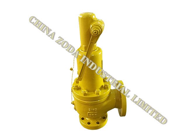
CHINA ZODA SAFETY VALVE is located in Yongjia County of Wenzhou, a place honored the title of "Home of Pumps and Valves in China". ZODA was established in 1994.We have five factories We has more than 480 workers,over 35 engineers,over 45 inspectors.With overseas investment, equipment and advanced management system.
KINGSTON High Pressure Safety Relief Valve, Model: 110C, Vent to Atmosphere Style, 3/8 in Nominal, NPT Connection, 95 psi Pressure Rating, Air, Gas Media, Lever Actuator, 0.296 sq-in Orifice, Red Brass Body, Hard Seat, Stainless Steel Seat, Brass Stem, Aluminum Seal, Trim Material: Brass Lock Nut/Music Wire/Stainless Steel Ball/Spring, Cold Rolled Steel Handle, 400 deg F, 3-3/4 in H Dimensions
Asafety valveis a device that prevents a system from overpressurizing. It consists of a valve with a spring-loaded mechanism that increases in force when the pressure exceeds a preset limit. It is generally used in compressed air or fluid systems. In some cases, it can prevent overpressure from resulting in system failures. This design of safety valves helps prevent disasters.
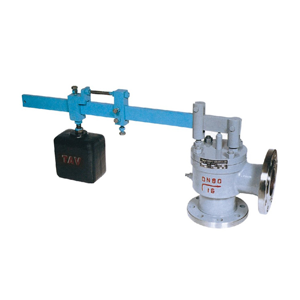
Safety valves come in three basic types. These include heavy hammer lever, spring, and pulse valves. The heavy hammer lever type of valve uses a lever or a heavy hammer to balance the force on the valve flap. The principle behind this type of safety valve is called leverage, which means it can use a small weight to exert a large amount of force. This type of safety valve also allows you to adjust the opening pressure.
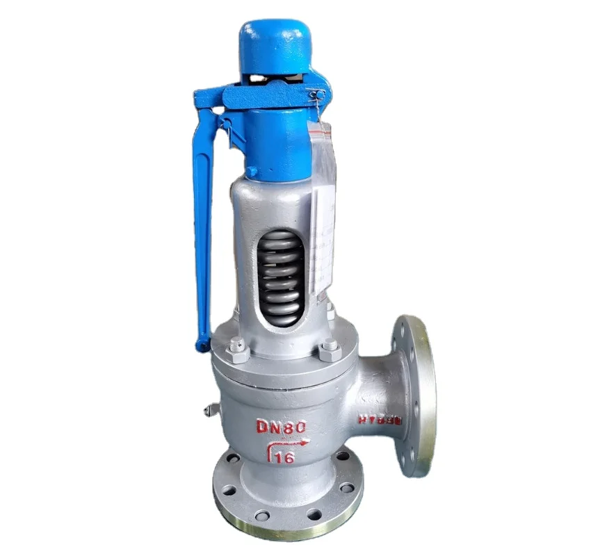
What are the different types of safety valves available? Here is a quick breakdown. A safety valve can be a spring-loaded valve; a Lever loaded valve, or a dead-weight safety-weight valve. The main differences between these valves are the mechanism by which they work and how they function. Spring-loaded safety valves can be easily adjusted. A lever-loaded safety-weight valve is generally less expensive.
There are several types of safety valves. One of them is a dead-weight safety valve. A dead weight safety valve is a safety valve that relies on a heavy disc that acts as a weight against a valve seat to prevent overpressure. A dead weight safety valve is a good choice for low-pressure vessels. Unlike other safety valves, dead weight safety valves do not have a spring. The weight of the disc acts to adjust the valve seat. When the pressure on the valve exceeds the normal pressure limit, it discharges the excess steam through a pipe.
The core of any safety valve is the spring. It must be durable and conform to all the specified requirements, including temperature and working medium. The spring material must be corrosion-resistant. For moderate temperature applications, carbon steel is used. For higher temperature and corrosive duty applications, tungsten steel or stainless steel is used. If the temperature is extremely high, special materials are used. Whether the safety valve is used in the air or water, it must be certified.
When purchasing a safety valve, you will find that there are several different options. Some safety valves have manual operation options. Typically, the manual operation will be performed during routine safety checks or maintenance. The actual flowing capacity will be reduced by 10%. The derated coefficient of discharge will also be calculated. As with most safety valves, there are several terms and definitions that are not included in the DIN 3320 standard.
Generally, a boiler will be fitted with high steam and low water safety valve. The low water safety valve is a combination of two valves. It operates when the water level in the boiler drops below a predetermined level. When the level drops too low, the lever safety valve operates, blowing with a loud noise. Fig. 5-4 shows how these safety valves work. They are located on the top or side of the boiler and are attached to the fire box or furnace.


 8613371530291