
main steam safety valve in stock

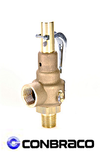
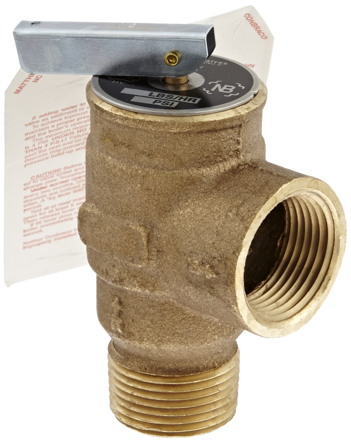
300LPM01-L is a safety relief valve for steam service on unfired pressure vessels. It is also used on Pressure Reducing Stations, Accumulators, Cleaners, and Distillers. Meets ASME code, Section VIII.
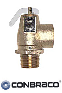
Model 300LPM01-K is a safety relief valve for air, gas and vapors. It is used on compressors, receivers, burners, dryers and other piping systems. Meets ASME code, Section VIII.
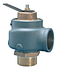
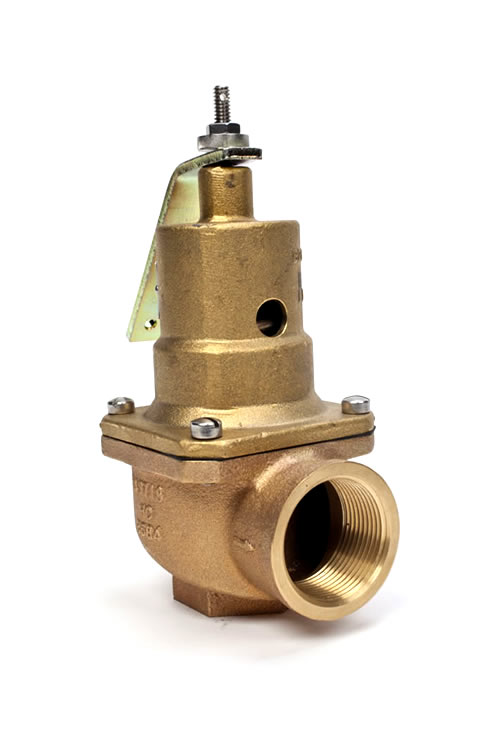
Safety valve for over pressure protection of steam boilers operating up to 250 psi. It is rated up to 250 psi and 406�F saturated steam. 6252 Safety valves meet ASME code, Section I.
Safety relief valve for steam service on unfired pressure vessels. It is also used on accumulators, cleaners, and distillers. Safety relief valves are rated up to 250 psi and 406�F of saturated steam and meet ASME code, Section VIII.
Safety relief valve for air, gas and vapors. It is used on compressors, receivers, burners, dryers and other piping systems. Figure 6252 safety relief valves are rated up to 250 psi and 406�F and meet ASME code, Section VIII.
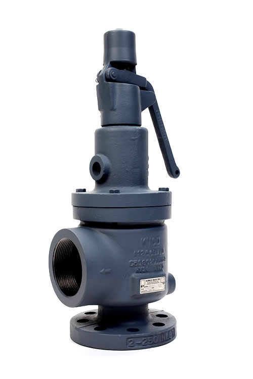
ASME Code Type--select--Section I; 6252FKK01-AS Steam Boiler Service, V stampSection VIII; 6252FKK01-LS Unfired Pressure Vessel Steam Service, UV stampSection VIII; 6252FKK01-KS Air Service, UV stamp
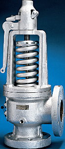
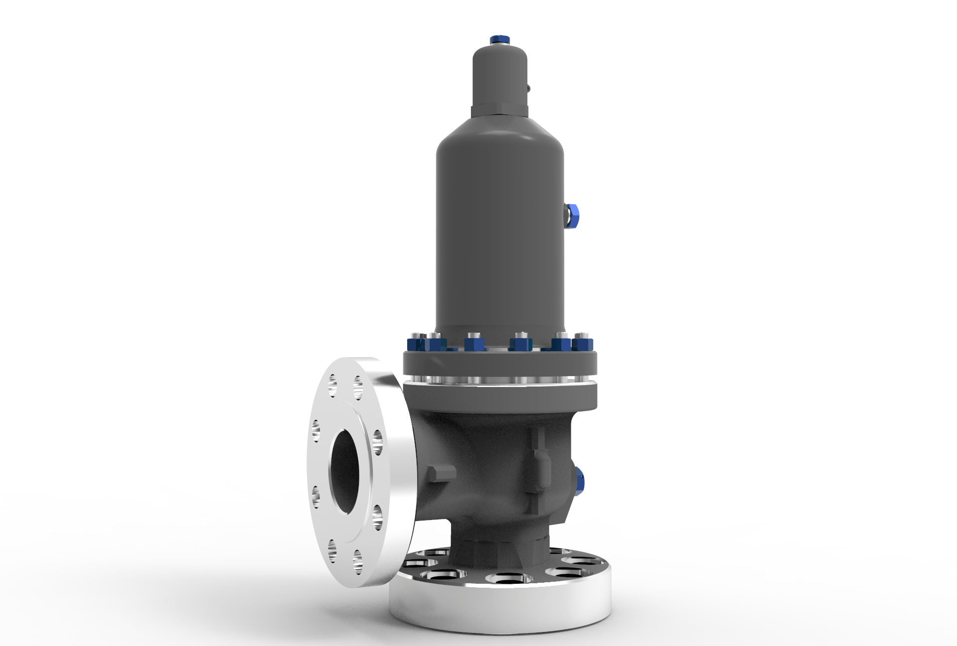
Baker Hughes’s Consolidated 3700 Series Safety Valves are spring-loaded safety valves for steam service. The 3700 Series Safety Valves are provided in accordance with the requirements of the ASME Code III, Division 1, Class 1 and 2, for materials, design, fabrication, examinations, pressure testing and overpressure protection. In addition these valves are provided in accordance with the Owner"s Design Specification. Every effort has been made to provide a design which can be readily serviced in the field and which has a high degree of reliability to meet the stringent needs of our Nuclear Power customers. 3700 Series Safety Valves are capacity certified, including demonstration of function under Section III of the ASME Code for application in Nuclear Power Systems and ASME PTC 25 (Power Test Code).

As soon as mankind was able to boil water to create steam, the necessity of the safety device became evident. As long as 2000 years ago, the Chinese were using cauldrons with hinged lids to allow (relatively) safer production of steam. At the beginning of the 14th century, chemists used conical plugs and later, compressed springs to act as safety devices on pressurised vessels.
Early in the 19th century, boiler explosions on ships and locomotives frequently resulted from faulty safety devices, which led to the development of the first safety relief valves.
In 1848, Charles Retchie invented the accumulation chamber, which increases the compression surface within the safety valve allowing it to open rapidly within a narrow overpressure margin.
Today, most steam users are compelled by local health and safety regulations to ensure that their plant and processes incorporate safety devices and precautions, which ensure that dangerous conditions are prevented.
The principle type of device used to prevent overpressure in plant is the safety or safety relief valve. The safety valve operates by releasing a volume of fluid from within the plant when a predetermined maximum pressure is reached, thereby reducing the excess pressure in a safe manner. As the safety valve may be the only remaining device to prevent catastrophic failure under overpressure conditions, it is important that any such device is capable of operating at all times and under all possible conditions.
Safety valves should be installed wherever the maximum allowable working pressure (MAWP) of a system or pressure-containing vessel is likely to be exceeded. In steam systems, safety valves are typically used for boiler overpressure protection and other applications such as downstream of pressure reducing controls. Although their primary role is for safety, safety valves are also used in process operations to prevent product damage due to excess pressure. Pressure excess can be generated in a number of different situations, including:
The terms ‘safety valve’ and ‘safety relief valve’ are generic terms to describe many varieties of pressure relief devices that are designed to prevent excessive internal fluid pressure build-up. A wide range of different valves is available for many different applications and performance criteria.
In most national standards, specific definitions are given for the terms associated with safety and safety relief valves. There are several notable differences between the terminology used in the USA and Europe. One of the most important differences is that a valve referred to as a ‘safety valve’ in Europe is referred to as a ‘safety relief valve’ or ‘pressure relief valve’ in the USA. In addition, the term ‘safety valve’ in the USA generally refers specifically to the full-lift type of safety valve used in Europe.
Pressure relief valve- A spring-loaded pressure relief valve which is designed to open to relieve excess pressure and to reclose and prevent the further flow of fluid after normal conditions have been restored. It is characterised by a rapid-opening ‘pop’ action or by opening in a manner generally proportional to the increase in pressure over the opening pressure. It may be used for either compressible or incompressible fluids, depending on design, adjustment, or application.
Safety valves are primarily used with compressible gases and in particular for steam and air services. However, they can also be used for process type applications where they may be needed to protect the plant or to prevent spoilage of the product being processed.
Relief valve - A pressure relief device actuated by inlet static pressure having a gradual lift generally proportional to the increase in pressure over opening pressure.
Relief valves are commonly used in liquid systems, especially for lower capacities and thermal expansion duty. They can also be used on pumped systems as pressure overspill devices.
Safety relief valve - A pressure relief valve characterised by rapid opening or pop action, or by opening in proportion to the increase in pressure over the opening pressure, depending on the application, and which may be used either for liquid or compressible fluid.
In general, the safety relief valve will perform as a safety valve when used in a compressible gas system, but it will open in proportion to the overpressure when used in liquid systems, as would a relief valve.
Safety valve- A valve which automatically, without the assistance of any energy other than that of the fluid concerned, discharges a quantity of the fluid so as to prevent a predetermined safe pressure being exceeded, and which is designed to re-close and prevent further flow of fluid after normal pressure conditions of service have been restored.

In order to ensure that the maximum allowable accumulation pressure of any system or apparatus protected by a safety valve is never exceeded, careful consideration of the safety valve’s position in the system has to be made. As there is such a wide range of applications, there is no absolute rule as to where the valve should be positioned and therefore, every application needs to be treated separately.
A common steam application for a safety valve is to protect process equipment supplied from a pressure reducing station. Two possible arrangements are shown in Figure 9.3.3.
The safety valve can be fitted within the pressure reducing station itself, that is, before the downstream stop valve, as in Figure 9.3.3 (a), or further downstream, nearer the apparatus as in Figure 9.3.3 (b). Fitting the safety valve before the downstream stop valve has the following advantages:
• The safety valve can be tested in-line by shutting down the downstream stop valve without the chance of downstream apparatus being over pressurised, should the safety valve fail under test.
• When setting the PRV under no-load conditions, the operation of the safety valve can be observed, as this condition is most likely to cause ‘simmer’. If this should occur, the PRV pressure can be adjusted to below the safety valve reseat pressure.
Indeed, a separate safety valve may have to be fitted on the inlet to each downstream piece of apparatus, when the PRV supplies several such pieces of apparatus.
• If supplying one piece of apparatus, which has a MAWP pressure less than the PRV supply pressure, the apparatus must be fitted with a safety valve, preferably close-coupled to its steam inlet connection.
• If a PRV is supplying more than one apparatus and the MAWP of any item is less than the PRV supply pressure, either the PRV station must be fitted with a safety valve set at the lowest possible MAWP of the connected apparatus, or each item of affected apparatus must be fitted with a safety valve.
• The safety valve must be located so that the pressure cannot accumulate in the apparatus viaanother route, for example, from a separate steam line or a bypass line.
It could be argued that every installation deserves special consideration when it comes to safety, but the following applications and situations are a little unusual and worth considering:
• Fire - Any pressure vessel should be protected from overpressure in the event of fire. Although a safety valve mounted for operational protection may also offer protection under fire conditions,such cases require special consideration, which is beyond the scope of this text.
• Exothermic applications - These must be fitted with a safety valve close-coupled to the apparatus steam inlet or the body direct. No alternative applies.
• Safety valves used as warning devices - Sometimes, safety valves are fitted to systems as warning devices. They are not required to relieve fault loads but to warn of pressures increasing above normal working pressures for operational reasons only. In these instances, safety valves are set at the warning pressure and only need to be of minimum size. If there is any danger of systems fitted with such a safety valve exceeding their maximum allowable working pressure, they must be protected by additional safety valves in the usual way.
In order to illustrate the importance of the positioning of a safety valve, consider an automatic pump trap (see Block 14) used to remove condensate from a heating vessel. The automatic pump trap (APT), incorporates a mechanical type pump, which uses the motive force of steam to pump the condensate through the return system. The position of the safety valve will depend on the MAWP of the APT and its required motive inlet pressure.
This arrangement is suitable if the pump-trap motive pressure is less than 1.6 bar g (safety valve set pressure of 2 bar g less 0.3 bar blowdown and a 0.1 bar shut-off margin). Since the MAWP of both the APT and the vessel are greater than the safety valve set pressure, a single safety valve would provide suitable protection for the system.
Here, two separate PRV stations are used each with its own safety valve. If the APT internals failed and steam at 4 bar g passed through the APT and into the vessel, safety valve ‘A’ would relieve this pressure and protect the vessel. Safety valve ‘B’ would not lift as the pressure in the APT is still acceptable and below its set pressure.
It should be noted that safety valve ‘A’ is positioned on the downstream side of the temperature control valve; this is done for both safety and operational reasons:
Operation - There is less chance of safety valve ‘A’ simmering during operation in this position,as the pressure is typically lower after the control valve than before it.
Also, note that if the MAWP of the pump-trap were greater than the pressure upstream of PRV ‘A’, it would be permissible to omit safety valve ‘B’ from the system, but safety valve ‘A’ must be sized to take into account the total fault flow through PRV ‘B’ as well as through PRV ‘A’.
A pharmaceutical factory has twelve jacketed pans on the same production floor, all rated with the same MAWP. Where would the safety valve be positioned?
One solution would be to install a safety valve on the inlet to each pan (Figure 9.3.6). In this instance, each safety valve would have to be sized to pass the entire load, in case the PRV failed open whilst the other eleven pans were shut down.
If additional apparatus with a lower MAWP than the pans (for example, a shell and tube heat exchanger) were to be included in the system, it would be necessary to fit an additional safety valve. This safety valve would be set to an appropriate lower set pressure and sized to pass the fault flow through the temperature control valve (see Figure 9.3.8).
Setpoint Integrated Solutions offers many Safety Valves to meet your specific application needs. Highlighted below is our wide array of Consolidated Products
The Consolidated Type 1700 Maxiflow High Pressure Safety Valve is a premium product that is installed on a majority of power generating stations worldwide to protect boilers from over-pressure conditions.
The Consolidated Type 1511 Steam Safety Valve are designed for low-pressure steam heating boilers and steam generators as well as air service applications
Safety valves are used in a variety of applications, including air/gas, vapor, steam and liquid service. Flotech has been approved by the National Board of Boiler and Pressure Vessel Inspectors to perform safety and relief valve testing, repair and certification.
Our valve experts will focus on getting your valves tested, repaired and quickly set to the exact specifications. We evaluate the repair condition of every valve and will recommend the right solution to manage your maintenance program.

The main purpose of a safety valve is to prevent the pressure in a system to exceed the certification pressure. Above certification pressure, no one can guaranty the systems safety - and especially for a steam system with very hot gas with huge amount of latent heat, the consequences can be dramatically.
The size of the safety valve depends primarily on the maximum boiler output and the operation pressure of the system. The safety valve shall as minimum have the evacuation capacity of all the vapor the boiler can produce running at full power at working (or certification) pressure.
The table below can be used to select a typical safety valve based on boiler output. Before final design, always consult the manufactures documentation.
Note! The table above is based on low pressure steam of 100 kN/m2 (1 bar)or 15 psiin imperial units. Latent heat of saturated steam is 2201 kJ/kg (945 Btu/lb). 1 N/m2 = 1 Pa = 1.4504 x 10⁻⁴ lb/in2 (psi) = 10-5 bar For higher pressure, steam is compressed and require less volume - required size of the valve reduced
Above certification pressure no one can guaranty the systems safety - and especially for a steam system with a very hot gas with a huge amount of latent heat the consequence with a failure can be dramatically.
The size of a safety valve depends primarily on the maximum boiler output and the operation pressure of the system. The safety valve must as minimum have the evacuation capacity of all the vapor the boiler can produce running at full power at the working (or certification) pressure. for a higher pressure the steam is compressed and requires less volume and the size of the valve can be reduced
The tables below can be used to select a typical safety valve in a high pressure system. Before the final design - always consult manufacturing documentation.
Note! The table above is based on steam with pressure 300 kPa (3 bar) (or 50 psiin imperial units). Latent heat of saturated steam is 1 N/m2 = 1 Pa = 1.4504 x 10⁻⁴ lb/in2 (psi) = 1x10⁻⁵ bar

Curtiss-Wright"s selection of Pressure Relief Valves comes from its outstanding product brands Farris and Target Rock. We endeavor to support the whole life cycle of a facility and continuously provide custom products and technologies. Boasting a reputation for producing high quality, durable products, our collection of Pressure Relief Valves is guaranteed to provide effective and reliable pressure relief.
While some basic components and activations in relieving pressure may differ between the specific types of relief valves, each aims to be 100% effective in keeping your equipment running safely. Our current range includes numerous valve types, from flanged to spring-loaded, threaded to wireless, pilot operated, and much more.
A pressure relief valve is a type of safety valve designed to control the pressure in a vessel. It protects the system and keeps the people operating the device safely in an overpressure event or equipment failure.
A pressure relief valve is designed to withstand a maximum allowable working pressure (MAWP). Once an overpressure event occurs in the system, the pressure relief valve detects pressure beyond its design"s specified capability. The pressure relief valve would then discharge the pressurized fluid or gas to flow from an auxiliary passage out of the system.
Below is an example of one of our pilot operated pressure relief valves in action; the cutaway demonstrates when high pressure is released from the system.
Air pressure relief valves can be applied to a variety of environments and equipment. Pressure relief valves are a safety valve used to keep equipment and the operators safe too. They"re instrumental in applications where proper pressure levels are vital for correct and safe operation. Such as oil and gas, power generation like central heating systems, and multi-phase applications in refining and chemical processing.
At Curtiss-Wright, we provide a range of different pressure relief valves based on two primary operations – spring-loaded and pilot operated. Spring-loaded valves can either be conventional spring-loaded or balanced spring-loaded.
Spring-loaded valves are programmed to open and close via a spring mechanism. They open when the pressure reaches an unacceptable level to release the material inside the vessel. It closes automatically when the pressure is released, and it returns to an average operating level. Spring-loaded safety valves rely on the closing force applied by a spring onto the main seating area. They can also be controlled in numerous ways, such as a remote, control panel, and computer program.
Pilot-operated relief valves operate by combining the primary relieving device (main valve) with self-actuated auxiliary pressure relief valves, also known as the pilot control. This pilot control dictates the opening and closing of the main valve and responds to system pressure. System pressure is fed from the inlet into and through the pilot control and ultimately into the main valve"s dome. In normal operating conditions, system pressure will prevent the main valve from opening.
The valves allow media to flow from an auxiliary passage and out of the system once absolute pressure is reached, whether it is a maximum or minimum level.
When the pressure is below the maximum amount, the pressure differential is slightly positive on the piston"s dome size, which keeps the main valve in the closed position. When system pressure rises and reaches the set point, the pilot will cut off flow to the dome, causing depressurization in the piston"s dome side. The pressure differential has reversed, and the piston will rise, opening the main valve, relieving pressure.
When the process pressure decreases to a specific pressure, the pilot closes, the dome is repressurized, and the main valve closes. The main difference between spring-loaded PRVs and pilot-operated is that a pilot-operated safety valve uses pressure to keep the valve closed.
Pilot-operated relief valves are controlled by hand and are typically opened often through a wheel or similar component. The user opens the valve when the gauge signifies that the system pressure is at an unsafe level; once the valve has opened and the pressure has been released, the operator can shut it by hand again.
Increasing pressure helps to maintain the pilot"s seal. Once the setpoint has been reached, the valve opens. This reduces leakage and fugitive emissions.
At set pressure the valve snaps to full lift. This can be quite violent on large pipes with significant pressure. The pressure has to drop below the set pressure in order for the piston to reseat.
At Curtiss-Wright we also provide solutions for pressure relief valve monitoring. Historically, pressure relief valves have been difficult or impossible to monitor. Our SmartPRV features a 2600 Series pressure relief valve accessorized with a wireless position monitor that alerts plant operators during an overpressure event, including the time and duration.
There are many causes of overpressure, but the most common ones are typically blocked discharge in the system, gas blowby, and fire. Even proper inspection and maintenance will not eliminate the occurrence of leakages. An air pressure relief valve is the only way to ensure a safe environment for the device, its surroundings, and operators.
A PRV and PSV are interchangeable, but there is a difference between the two valves. A pressure release valve gradually opens when experiencing pressure, whereas a pressure safety valve opens suddenly when the pressure hits a certain level of over pressurization. Safety valves can be used manually and are typically used for a permanent shutdown. Air pressure relief valves are used for operational requirements, and they gently release the pressure before it hits the maximum high-pressure point and circulates it back into the system.
Pressure relief valves should be subject to an annual test, one per year. The operator is responsible for carrying out the test, which should be done using an air compressor. It’s imperative to ensure pressure relief valves maintain their effectiveness over time and are checked for signs of corrosion and loss of functionality. Air pressure relief valves should also be checked before their installation, after each fire event, and regularly as decided by the operators.
Direct-acting solenoid valves have a direct connection with the opening and closing armature, whereas pilot-operated valves use of the process fluid to assist in piloting the operation of the valve.
A control valve works by varying the rate of fluid passing through the valve itself. As the valve stem moves, it alters the size of the passage and increases, decreases or holds steady the flow. The opening and closing of the valve is altered whenever the controlled process parameter does not reach the set point.
Control valves are usually at floor level or easily accessible via platforms. They are also located on the same equipment or pipeline as the measurement and downstream or flow measurements.
An industrial relief valve is designed to control or limit surges of pressure in a system, most often in fluid or compressed air system valves. It does so as a form of protection for the system and defending against instrument or equipment failure. They are usually present in clean water industries.
A PRV is often referred to as a pressure relief valve, which is also known as a PSV or pressure safety valve. They are used interchangeably throughout the industry depending on company standards.

The primary purpose of a safety valve is to protect life, property and the environment. Safety valves are designed to open and release excess pressure from vessels or equipment and then close again.
The function of safety valves differs depending on the load or main type of the valve. The main types of safety valves are spring-loaded, weight-loaded and controlled safety valves.
Regardless of the type or load, safety valves are set to a specific set pressure at which the medium is discharged in a controlled manner, thus preventing overpressure of the equipment. In dependence of several parameters such as the contained medium, the set pressure is individual for each safety application.
Industry leading pressure and safety relief valve designs with over 140 years of technical and application expertise providing custom engineered solutions for O&G, Refining, Chemical, Petrochemical, Process and Power applications. Our designs meet global and local codes and standards (API 526; ASME Section I, IV & VIII; EN ISO 4126; PED & more). Gain insight into the performance of your pressure relief valves with wireless monitoring.
Years ago, it was not uncommon to read news about tragic boiler explosions, sometimes resulting in mass destruction. Today, boilers are equipped with important safety devises to help protect against these types of catastrophes. Let’s take a look at the most critical of these devices: the safety valve.
The safety valve is one of the most important safety devices in a steam system. Safety valves provide a measure of security for plant operators and equipment from over pressure conditions. The main function of a safety valve is to relieve pressure. It is located on the boiler steam drum, and will automatically open when the pressure of the inlet side of the valve increases past the preset pressure. All boilers are required by ASME code to have at least one safety valve, dependent upon the maximum flow capacity (MFC) of the boiler. The total capacity of the safety valve at the set point must exceed the steam control valve’s MFC if the steam valve were to fail to open. In most cases, two safety valves per boiler are required, and a third may be needed if they do not exceed the MFC.
There are three main parts to the safety valve: nozzle, disc, and spring. Pressurized steam enters the valve through the nozzle and is then threaded to the boiler. The disc is the lid to the nozzle, which opens or closes depending on the pressure coming from the boiler. The spring is the pressure controller.
As a boiler starts to over pressure, the nozzle will start to receive a higher pressure coming from the inlet side of the valve, and will start to sound like it is simmering. When the pressure becomes higher than the predetermined pressure of the spring, the disc will start to lift and release the steam, creating a “pop” sound. After it has released and the steam and pressure drops below the set pressure of the valve, the spring will close the disc. Once the safety valve has popped, it is important to check the valve to make sure it is not damaged and is working properly.
A safety valve is usually referred to as the last line of safety defense. Without safety valves, the boiler can exceed it’s maximum allowable working pressure (MAWP) and not only damage equipment, but also injure or kill plant operators that are close by. Many variables can cause a safety valve on a boiler to lift, such as a compressed air or electrical power failure to control instrumentation, or an imbalance of feedwater rate caused by an inadvertently shut or open isolation valve.
Once a safety valve has lifted, it is important to do a complete boiler inspection and confirm that there are no other boiler servicing issues. A safety valve should only do its job once; safety valves should not lift continuously. Lastly, it is important to have the safety valves fully repaired, cleaned and recertified with a National Board valve repair (VR) stamp as required by local code or jurisdiction. Safety valves are a critical component in a steam system, and must be maintained.
All of Nationwide Boiler’s rental boilers include on to two safety valves depending on the size; one set at design pressure and the other set slightly higher than design. By request, we can reset the safeties to a lower pressure if the application requires it. In addition, the valves are thoroughly checked after every rental and before going out to a new customer, and they are replaced and re-certified as needed.
RM2BHFJN7–Coryton, Stanford-le-Hope, Essex, UK. 25th Apr, 2020. A build up of pressure caused a safety valve to release at a power station (initially thought to be the oil refinery nearby) in Coryton, close to DP World port cranes on the Thames Estuary, creating steam and noise in the area leading people to believe that there had been an explosion. Local fire brigade and emergency services attended
RMT94YD7–Papin holding a diagram of a steam engine, lithograph, 1689. Denis Papin (August 22, 1647 - 1712) was a French physicist, mathematician and inventor. He worked with Robert Boyle from 1676-79, publishing an account of his work in Continuation of New Experiments (1680). During this period, Papin invented the steam digester, a type of pressure cooker with a safety valve.
RMGE4JB3–(September 6, 1963) Vent flowing cryogenic fuel and T/C Rake mounted on a 1/10 scale model Centaur in the l0 x l0 Foot Supersonic Wind Tunnel. The fuel being used is liquid hydrogen. The point of the test is to determine how far to expel venting fuel from the rocket body to prevent explosion at the base of the vehicle. This vent is used as a safety valve for the fumes created when loading the fuel tanks during launch preparation. Liquid hydrogen has to be kept at a very low temperature. As it heats, it turns to gas and increases pressure in the tank. It therefore has to be vented overboard whi
RMMR3WYE–Illustration depicting Papin"s steam engine (1707) for pumping water from mines. It was the first engine to use the safety valve he had invented twenty-seven years earlier for his "digester". (1647-1713) a French physicist, mathematician and inventor, best known for his pioneering invention of the steam digester, the forerunner of the pressure cooker and of the steam engine. Dated 19th century
RM2BHFJR5–Coryton, Stanford-le-Hope, Essex, UK. 25th Apr, 2020. A build up of pressure caused a safety valve to release at a power station (initially thought to be the oil refinery nearby) in Coryton, close to DP World port cranes on the Thames Estuary, creating steam and noise in the area leading people to believe that there had been an explosion. Local fire brigade and emergency services attended
RME14RJF–Apr. 18, 2012 - The main road through the area is always busy: The gaunt, Barren Hills are a constant reminder of the wilderness of the territory afar. The safety valve with its ever-burning flame at the top is behind the wire pending on the night.
RMCYXCAB–A well engineered brass and ferrous metal model gas fired horizontal stationary steam set, The brass boiler with metal cladding and normal fittings, weight and lever safety valve, main stop and lagged steam line to single horizontal cylinder¦ mill engine with overmounted valve chest and brass bound cylinder, barrelled connecting rod, counterbalanced crankshaft, spoked flywheel and multi rope pulley. Other details include feed water heater and hand feed pump ,the whole finished in maroon, black and polished brightwork and mounted on a brick and tiled plinth with, Additional-Rights-Clearences-NA
RMT965J2–Color enhanced lithograph of Papin holding a diagram of a steam engine, 1689. Denis Papin (August 22, 1647 - 1712) was a French physicist, mathematician and inventor. He worked with Robert Boyle from 1676-79, publishing an account of his work in Continuation of New Experiments (1680). During this period, Papin invented the steam digester, a type of pressure cooker with a safety valve.
RMW56XWK–Model of a Hydraulic Press, Model of a simple hydraulic press on a wooden floorboard. On the one hand is a manually operated pump, equipped with a pump arm, regulator, overflow and safety valve. The pump arm can be set in two positions. The regulator is a screw valve. The safety valve is adjusted with a weight. A tube for the liquid runs from the pump to the bottom of the press, where an oval press platform is pushed upwards., Joseph Bramah (possibly), United Kingdom, 1820, iron (metal), copper (metal), wood (plant material), model: h 41 cm × w 56 cm × d 27 cm packaging capsule: h 45.5 cm × w
RMMR3X05–Illustration depicting Papin"s steam engine (1707) for pumping water from mines. It was the first engine to use the safety valve he had invented twenty-seven years earlier for his "digester". (1647-1713) a French physicist, mathematician and inventor, best known for his pioneering invention of the steam digester, the forerunner of the pressure cooker and of the steam engine. Dated 19th century
RM2JM8GB6–Alain Sauthier, Director of Nant de Drance poses in front of a safety valve of the penstock in the newly operational Nant de Drance pumped storage electricity power plant in Finhaut, Switzerland, August 4, 2022. REUTERS/Denis Balibouse
RMCYXC6B–A well engineered brass and ferrous metal model gas fired horizontal stationary steam set, The brass boiler with metal cladding and normal fittings, weight and lever safety valve, main stop and lagged steam line to single horizontal cylinder¦ mill engine with overmounted valve chest and brass bound cylinder, barrelled connecting rod, counterbalanced crankshaft, spoked flywheel and multi rope pulley. Other details include feed water heater and hand feed pump ,the whole finished in maroon, black and polished brightwork and mounted on a brick and tiled plinth with, Additional-Rights-Clearences-NA
RF2JHG6MN–An industrial pressure safety valve, abbreviated as "psv" a well-known concept in the industry. Specially made to prevent dangerous high pressures in
RMP3880C–. Grand Geyser Cone and safety valve, Yellowstone National Park. Coverage: 1881-1889. Source Imprint: Fargo, D.T. : F. Jay Haynes, 1881-1889.. Digital item published 1-25-2006; updated 2-12-2009. 129 Grand Geyser Cone and safety valve, Yellowstone National Park, by Haynes, F. Jay (Frank Jay), 1853-1921
RM2JM8G81–Alain Sauthier, Director of Nant de Drance talks to a journalist in front of a safety valve of the penstock in the newly operational Nant de Drance pumped storage electricity power plant in Finhaut, Switzerland, August 4, 2022. REUTERS/Denis Balibouse
RF2JHG6N4–An industrial pressure safety valve, abbreviated as "psv" a well-known concept in the industry. Specially made to prevent dangerous high pressures in
RMP38806–. Grand Geyser Cone and safety valve, Yellowstone National Park. Coverage: 1881-1889. Source Imprint: Fargo, D.T. : F. Jay Haynes, 1881-1889.. Digital item published 1-25-2006; updated 2-12-2009. 129 Grand Geyser Cone and safety valve, Yellowstone National Park, by Haynes, F. Jay (Frank Jay), 1853-1921 2
RM2D3PPTK–Iraqi looters wave to the passing convoy of U.S. Marines as they ride a stolen small construction vehicle in the suburbs of Iraqi capital Baghdad April 7, 2003. British Air Marshal Brian Burridge said during his briefing at Central Command on Monday looting was almost "an inevitability". "There is a release of pent up annoyance and hatred against the Ba"ath Party and the Ba"ath regime but once that safety valve is blown...the business of protecting property becomes easier," he said. REUTERS/Oleg Popov OP/AA
RMTWH30F–Relief and safety valve of turbine unit no. 1, located in the subway below the Generator Room; looking south. The safety valve was manufactured by the Chapman Valve Company of Springfield, Massachusetts. It is identical to the adjacent safety valve for turbine unit no. 2. Photo by Jet Lowe, HAER, 1989. - Puget Sound Power and Light Company, White River Hydroelectric Project, 600 North River Avenue, Dieringer, Pierce County, WA; Shuffletin, Samuel L; Stine, Charles; Webster, Edwin; Baker, Charles H
RMD6K57N–A technician walks away from the safety valve of the drill on the drilling platform of German-Canadian oil company Firma CEP (Central European Petroleum GmbH) near Pudagla on the island of Usedom, Germany, 02 April 2012. After suspedning the controversial search for oil on Usedom in the fall of 2011, work on the the platform now starts up again. Photo: STEFAN SAUER
RM2CF74YH–Vent flowing cryogenic fuel and T/C Rake mounted on a 1/10 scale model Centaur in the l0 x l0 Foot Supersonic Wind Tunnel. The fuel being used is liquid hydrogen. The point of the test is to determine how far to expel venting fuel from the rocket body to prevent explosion at the base of the vehicle. This vent is used as a safety valve for the fumes created when loading the fuel tanks during launch preparation. Liquid hydrogen has to be kept at a very low temperature. As it heats, it turns to gas and increases pressure in the tank. It therefore has to be vented overboard while the rocket sits o


 8613371530291