
main steam safety valve factory

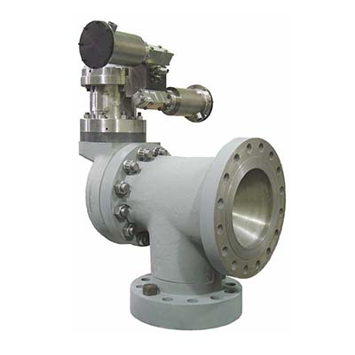
Baker Hughes’s Consolidated 3700 Series Safety Valves are spring-loaded safety valves for steam service. The 3700 Series Safety Valves are provided in accordance with the requirements of the ASME Code III, Division 1, Class 1 and 2, for materials, design, fabrication, examinations, pressure testing and overpressure protection. In addition these valves are provided in accordance with the Owner"s Design Specification. Every effort has been made to provide a design which can be readily serviced in the field and which has a high degree of reliability to meet the stringent needs of our Nuclear Power customers. 3700 Series Safety Valves are capacity certified, including demonstration of function under Section III of the ASME Code for application in Nuclear Power Systems and ASME PTC 25 (Power Test Code).

As soon as mankind was able to boil water to create steam, the necessity of the safety device became evident. As long as 2000 years ago, the Chinese were using cauldrons with hinged lids to allow (relatively) safer production of steam. At the beginning of the 14th century, chemists used conical plugs and later, compressed springs to act as safety devices on pressurised vessels.
Early in the 19th century, boiler explosions on ships and locomotives frequently resulted from faulty safety devices, which led to the development of the first safety relief valves.
In 1848, Charles Retchie invented the accumulation chamber, which increases the compression surface within the safety valve allowing it to open rapidly within a narrow overpressure margin.
Today, most steam users are compelled by local health and safety regulations to ensure that their plant and processes incorporate safety devices and precautions, which ensure that dangerous conditions are prevented.
The principle type of device used to prevent overpressure in plant is the safety or safety relief valve. The safety valve operates by releasing a volume of fluid from within the plant when a predetermined maximum pressure is reached, thereby reducing the excess pressure in a safe manner. As the safety valve may be the only remaining device to prevent catastrophic failure under overpressure conditions, it is important that any such device is capable of operating at all times and under all possible conditions.
Safety valves should be installed wherever the maximum allowable working pressure (MAWP) of a system or pressure-containing vessel is likely to be exceeded. In steam systems, safety valves are typically used for boiler overpressure protection and other applications such as downstream of pressure reducing controls. Although their primary role is for safety, safety valves are also used in process operations to prevent product damage due to excess pressure. Pressure excess can be generated in a number of different situations, including:
The terms ‘safety valve’ and ‘safety relief valve’ are generic terms to describe many varieties of pressure relief devices that are designed to prevent excessive internal fluid pressure build-up. A wide range of different valves is available for many different applications and performance criteria.
In most national standards, specific definitions are given for the terms associated with safety and safety relief valves. There are several notable differences between the terminology used in the USA and Europe. One of the most important differences is that a valve referred to as a ‘safety valve’ in Europe is referred to as a ‘safety relief valve’ or ‘pressure relief valve’ in the USA. In addition, the term ‘safety valve’ in the USA generally refers specifically to the full-lift type of safety valve used in Europe.
Pressure relief valve- A spring-loaded pressure relief valve which is designed to open to relieve excess pressure and to reclose and prevent the further flow of fluid after normal conditions have been restored. It is characterised by a rapid-opening ‘pop’ action or by opening in a manner generally proportional to the increase in pressure over the opening pressure. It may be used for either compressible or incompressible fluids, depending on design, adjustment, or application.
Safety valves are primarily used with compressible gases and in particular for steam and air services. However, they can also be used for process type applications where they may be needed to protect the plant or to prevent spoilage of the product being processed.
Relief valve - A pressure relief device actuated by inlet static pressure having a gradual lift generally proportional to the increase in pressure over opening pressure.
Relief valves are commonly used in liquid systems, especially for lower capacities and thermal expansion duty. They can also be used on pumped systems as pressure overspill devices.
Safety relief valve - A pressure relief valve characterised by rapid opening or pop action, or by opening in proportion to the increase in pressure over the opening pressure, depending on the application, and which may be used either for liquid or compressible fluid.
In general, the safety relief valve will perform as a safety valve when used in a compressible gas system, but it will open in proportion to the overpressure when used in liquid systems, as would a relief valve.
Safety valve- A valve which automatically, without the assistance of any energy other than that of the fluid concerned, discharges a quantity of the fluid so as to prevent a predetermined safe pressure being exceeded, and which is designed to re-close and prevent further flow of fluid after normal pressure conditions of service have been restored.
Valvesonly Europe is one of the best Steam safety valve manufacturer in germany. The steam safety valve is used to protect the equipment from being subjected to excessive pressure. Pressure relief valves are another name for safety valves. Steam valves regulate the flow and pressure of steam and heated water vapour. Steam valves are used to reduce the pressure of inlet steam for process applications. A steam valve can control temperature in addition to pressure. Steam valves’ primary function is to regulate the temperature and pressure of inlet steam for process applications. To put it another way, it regulates steam production. A steam valve may also regulate temperature in addition to pressure. It is frequently used at lower pressures in manufacturing processes. Lowering the steam pressure would improve plant safety as well. These are precise enough for industrial applications. We offer a Steam Valve that has a low wear rate and a long service life. The steam safety valve is used to prevent the equipment from being damaged by excessive pressure and expanding steam. They’re used to keep steam systems and engines from overheating. This valve’s primary purpose is to relieve strain, either manually or automatically. Wherever the maximum permissible operating pressure or pressure in the equipment is likely to be surpassed, it should be mounted.
Steam safety valve is to relieve pressure. It is located on the boiler steam drum, and will automatically open when the pressure of the inlet side of the valve increases past the present pressure. Safety Valve is to protect life and property against failure to control system pressures, it offers the last means of reducing system pressure before total failure

Safety valves are an arrangement or mechanism to release a substance from the concerned system in the event of pressure or temperature exceeding a particular preset limit. The systems in the context may be boilers, steam boilers, pressure vessels or other related systems. As per the mechanical arrangement, this one get fitted into the bigger picture (part of the bigger arrangement) called as PSV or PRV that is pressure safety or pressure relief valves.
This type of safety mechanism was largely implemented to counter the problem of accidental explosion of steam boilers. Initiated in the working of a steam digester, there were many methodologies that were then accommodated during the phase of the industrial revolution. And since then this safety mechanism has come a long way and now accommodates various other aspects.
These aspects like applications, performance criteria, ranges, nation based standards (countries like United States, European Union, Japan, South Korea provide different standards) etc. manage to differentiate or categorize this safety valve segment. So, there can be many different ways in which these safety valves get differentiated but a common range of bifurcation is as follows:
The American Society of Mechanical Engineers (ASME) I tap is a type of safety valve which opens with respect to 3% and 4% of pressure (ASME code for pressure vessel applications) while ASME VIII valve opens at 10% over pressure and closes at 7%. Lift safety valves get further classified as low-lift and full lift. The flow control valves regulate the pressure or flow of a fluid whereas a balanced valve is used to minimize the effects induced by pressure on operating characteristics of the valve in context.
A power operated valve is a type of pressure relief valve is which an external power source is also used to relieve the pressure. A proportional-relief valve gets opened in a relatively stable manner as compared to increasing pressure. There are 2 types of direct-loaded safety valves, first being diaphragms and second: bellows. diaphragms are valves which spring for the protection of effects of the liquid membrane while bellows provide an arrangement where the parts of rotating elements and sources get protected from the effects of the liquid via bellows.
In a master valve, the operation and even the initiation is controlled by the fluid which gets discharged via a pilot valve. Now coming to the bigger picture, the pressure safety valves based segment gets classified as follows:
So all in all, pressure safety valves, pressure relief valves, relief valves, pilot-operated relief valves, low pressure safety valves, vacuum pressure safety valves etc. complete the range of safety measures in boilers and related devices.
Safety valves have different discharge capacities. These capacities are based on the geometrical area of the body seat upstream and downstream of the valve. Flow diameter is the minimum geometrical diameter upstream and downstream of the body seat.
The nominal size designation refers to the inlet orifice diameter. A safety Valve"s theoretical flowing capacity is the mass flow through an orifice with the same cross-sectional area as the valve"s flow area. This capacity does not account for the flow losses caused by the valve. The actual capacity is measured, and the certified flow capacity is the actual flow capacity reduced by 10%.
A safety valve"s discharge capacity is dependent on the set pressure and position in a system. Once the set pressure is calculated, the discharge capacity must be determined. Safety valves may be oversized or undersized depending on the flow throughput and/or the valve"s set pressure.
The actual discharge capacity of a safety valve depends on the type of discharge system used. In liquid service, safety valves are generally automatic and direct-pressure actuated.
A safety valve is used to protect against overpressure in a fluid system. Its design allows for a lift in the disc, indicating that the valve is about to open. When the inlet pressure rises above the set pressure, the guide moves to the open position, and media flows to the outlet via the pilot tube. Once the inlet pressure falls below the set pressure, the main valve closes and prevents overpressure. There are five criteria for selecting a safety valve.
The first and most basic requirement of a safety valve is its ability to safely control the flow of gas. Hence, the valve must be able to control the flow of gas and water. The valve should be able to withstand the high pressures of the system. This is because the gas or steam coming from the boiler will be condensed and fill the pipe. The steam will then wet the safety valve seat.
The other major requirement for safety valves is their ability to prevent pressure buildup. They prevent overpressure conditions by allowing liquid or gas to escape. Safety valves are used in many different applications. Gas and steam lines, for example, can prevent catastrophic damage to the plant. They are also known as safety relief valves. During an emergency, a safety valve will open automatically and discharge gas or liquid pressure from a pressurized system, preventing it from reaching dangerous levels.
The discharge capacity of a safety valve is based on its orifice area, set pressure, and position in the system. A safety valve"s discharge capacity should be calculated based on the maximum flow through its inlet and outlet orifice areas. Its nominal size is often determined by manufacturer specifications.
Its discharge capacity is the maximum flow through the valve that it can relieve, based on the maximum flow through each individual flow path or combined flow path. The discharge pressure of the safety valve should be more than the operating pressure of the system. As a thumb rule, the relief pressure should be 10% above the working pressure of the system.
It is important to choose the discharge capacity of a safety valve based on the inlet and output piping sizes. Ideally, the discharge capacity should be equal to or greater than the maximum output of the system. A safety valve should also be installed vertically and into a clean fitting. While installing a valve, it is important to use a proper wrench for installation. The discharge piping should slope downward to drain any condensate.
The discharge capacity of a safety valve is measured in a few different ways. The first is the test pressure. This gauge pressure is the pressure at which the valve opens, while the second is the pressure at which it re-closes. Both are measured in a test stand under controlled conditions. A safety valve with a test pressure of 10,000 psi is rated at 10,000 psi (as per ASME PTC25.3).
The discharge capacity of a safety valve should be large enough to dissipate a large volume of pressure. A small valve may be adequate for a smaller system, but a larger one could cause an explosion. In a large-scale manufacturing plant, safety valves are critical for the safety of personnel and equipment. Choosing the right valve size for a particular system is essential to its efficiency.
Before you use a safety valve, you need to know its discharge capacity. Here are some steps you need to follow to calculate the discharge capacity of a safety valve.
To check the discharge capacity of a safety valve, the safety valve should be installed in the appropriate location. Its inlet and outlet pipework should be thoroughly cleaned before installation. It is important to avoid excessive use of PTFE tape and to ensure that the installation is solid. The safety valve should not be exposed to vibration or undue stress. When mounting a safety valve, it should be installed vertically and with the test lever at the top. The inlet connection of the safety valve should be attached to the vessel or pipeline with the shortest length of pipe. It must not be interrupted by any isolation valve. The pressure loss at the inlet of a safety valve should not exceed 3% of the set pressure.
The sizing of a safety valve depends on the amount of fluid it is required to control. The rated discharge capacity is a function of the safety valve"s orifice area, set pressure, and position in the system. Using the manufacturer"s specifications for orifice area and nominal size of the valve, the capacity of a safety valve can be determined. The discharge flow can be calculated using the maximum flow through the valve or the combined flows of several paths. When sizing a safety valve, it"s necessary to consider both its theoretical and actual discharge capacity. Ideally, the discharge capacity will be equal to the minimum area.
To determine the correct set pressure for a safety valve, consider the following criteria. It must be less than the MAAP of the system. Set pressure of 5% greater than the MAAP will result in an overpressure of 10%. If the set pressure is higher than the MAAP, the safety valve will not close. The MAAP must never exceed the set pressure. A set pressure that is too high will result in a poor shutoff after discharge. Depending on the type of valve, a backpressure variation of 10% to 15% of the set pressure cannot be handled by a conventional valve.
Curtiss-Wright"s selection of Pressure Relief Valves comes from its outstanding product brands Farris and Target Rock. We endeavor to support the whole life cycle of a facility and continuously provide custom products and technologies. Boasting a reputation for producing high quality, durable products, our collection of Pressure Relief Valves is guaranteed to provide effective and reliable pressure relief.
While some basic components and activations in relieving pressure may differ between the specific types of relief valves, each aims to be 100% effective in keeping your equipment running safely. Our current range includes numerous valve types, from flanged to spring-loaded, threaded to wireless, pilot operated, and much more.
A pressure relief valve is a type of safety valve designed to control the pressure in a vessel. It protects the system and keeps the people operating the device safely in an overpressure event or equipment failure.
A pressure relief valve is designed to withstand a maximum allowable working pressure (MAWP). Once an overpressure event occurs in the system, the pressure relief valve detects pressure beyond its design"s specified capability. The pressure relief valve would then discharge the pressurized fluid or gas to flow from an auxiliary passage out of the system.
Below is an example of one of our pilot operated pressure relief valves in action; the cutaway demonstrates when high pressure is released from the system.
Air pressure relief valves can be applied to a variety of environments and equipment. Pressure relief valves are a safety valve used to keep equipment and the operators safe too. They"re instrumental in applications where proper pressure levels are vital for correct and safe operation. Such as oil and gas, power generation like central heating systems, and multi-phase applications in refining and chemical processing.
At Curtiss-Wright, we provide a range of different pressure relief valves based on two primary operations – spring-loaded and pilot operated. Spring-loaded valves can either be conventional spring-loaded or balanced spring-loaded.
Spring-loaded valves are programmed to open and close via a spring mechanism. They open when the pressure reaches an unacceptable level to release the material inside the vessel. It closes automatically when the pressure is released, and it returns to an average operating level. Spring-loaded safety valves rely on the closing force applied by a spring onto the main seating area. They can also be controlled in numerous ways, such as a remote, control panel, and computer program.
Pilot-operated relief valves operate by combining the primary relieving device (main valve) with self-actuated auxiliary pressure relief valves, also known as the pilot control. This pilot control dictates the opening and closing of the main valve and responds to system pressure. System pressure is fed from the inlet into and through the pilot control and ultimately into the main valve"s dome. In normal operating conditions, system pressure will prevent the main valve from opening.
The valves allow media to flow from an auxiliary passage and out of the system once absolute pressure is reached, whether it is a maximum or minimum level.
When the pressure is below the maximum amount, the pressure differential is slightly positive on the piston"s dome size, which keeps the main valve in the closed position. When system pressure rises and reaches the set point, the pilot will cut off flow to the dome, causing depressurization in the piston"s dome side. The pressure differential has reversed, and the piston will rise, opening the main valve, relieving pressure.
When the process pressure decreases to a specific pressure, the pilot closes, the dome is repressurized, and the main valve closes. The main difference between spring-loaded PRVs and pilot-operated is that a pilot-operated safety valve uses pressure to keep the valve closed.
Pilot-operated relief valves are controlled by hand and are typically opened often through a wheel or similar component. The user opens the valve when the gauge signifies that the system pressure is at an unsafe level; once the valve has opened and the pressure has been released, the operator can shut it by hand again.
Increasing pressure helps to maintain the pilot"s seal. Once the setpoint has been reached, the valve opens. This reduces leakage and fugitive emissions.
At set pressure the valve snaps to full lift. This can be quite violent on large pipes with significant pressure. The pressure has to drop below the set pressure in order for the piston to reseat.
At Curtiss-Wright we also provide solutions for pressure relief valve monitoring. Historically, pressure relief valves have been difficult or impossible to monitor. Our SmartPRV features a 2600 Series pressure relief valve accessorized with a wireless position monitor that alerts plant operators during an overpressure event, including the time and duration.
There are many causes of overpressure, but the most common ones are typically blocked discharge in the system, gas blowby, and fire. Even proper inspection and maintenance will not eliminate the occurrence of leakages. An air pressure relief valve is the only way to ensure a safe environment for the device, its surroundings, and operators.
A PRV and PSV are interchangeable, but there is a difference between the two valves. A pressure release valve gradually opens when experiencing pressure, whereas a pressure safety valve opens suddenly when the pressure hits a certain level of over pressurization. Safety valves can be used manually and are typically used for a permanent shutdown. Air pressure relief valves are used for operational requirements, and they gently release the pressure before it hits the maximum high-pressure point and circulates it back into the system.
Pressure relief valves should be subject to an annual test, one per year. The operator is responsible for carrying out the test, which should be done using an air compressor. It’s imperative to ensure pressure relief valves maintain their effectiveness over time and are checked for signs of corrosion and loss of functionality. Air pressure relief valves should also be checked before their installation, after each fire event, and regularly as decided by the operators.
Direct-acting solenoid valves have a direct connection with the opening and closing armature, whereas pilot-operated valves use of the process fluid to assist in piloting the operation of the valve.
A control valve works by varying the rate of fluid passing through the valve itself. As the valve stem moves, it alters the size of the passage and increases, decreases or holds steady the flow. The opening and closing of the valve is altered whenever the controlled process parameter does not reach the set point.
Control valves are usually at floor level or easily accessible via platforms. They are also located on the same equipment or pipeline as the measurement and downstream or flow measurements.
An industrial relief valve is designed to control or limit surges of pressure in a system, most often in fluid or compressed air system valves. It does so as a form of protection for the system and defending against instrument or equipment failure. They are usually present in clean water industries.
A PRV is often referred to as a pressure relief valve, which is also known as a PSV or pressure safety valve. They are used interchangeably throughout the industry depending on company standards.

The primary purpose of a safety valve is to protect life, property and the environment. Safety valves are designed to open and release excess pressure from vessels or equipment and then close again.
The function of safety valves differs depending on the load or main type of the valve. The main types of safety valves are spring-loaded, weight-loaded and controlled safety valves.
Regardless of the type or load, safety valves are set to a specific set pressure at which the medium is discharged in a controlled manner, thus preventing overpressure of the equipment. In dependence of several parameters such as the contained medium, the set pressure is individual for each safety application.

A little product education can make you look super smart to customers, which usually means more orders for everything you sell. Here’s a few things to keep in mind about safety valves, so your customers will think you’re a genius.
A safety valve is required on anything that has pressure on it. It can be a boiler (high- or low-pressure), a compressor, heat exchanger, economizer, any pressure vessel, deaerator tank, sterilizer, after a reducing valve, etc.
There are four main types of safety valves: conventional, bellows, pilot-operated, and temperature and pressure. For this column, we will deal with conventional valves.
A safety valve is a simple but delicate device. It’s just two pieces of metal squeezed together by a spring. It is passive because it just sits there waiting for system pressure to rise. If everything else in the system works correctly, then the safety valve will never go off.
A safety valve is NOT 100% tight up to the set pressure. This is VERY important. A safety valve functions a little like a tea kettle. As the temperature rises in the kettle, it starts to hiss and spit when the water is almost at a boil. A safety valve functions the same way but with pressure not temperature. The set pressure must be at least 10% above the operating pressure or 5 psig, whichever is greater. So, if a system is operating at 25 psig, then the minimum set pressure of the safety valve would be 30 psig.
Most valve manufacturers prefer a 10 psig differential just so the customer has fewer problems. If a valve is positioned after a reducing valve, find out the max pressure that the equipment downstream can handle. If it can handle 40 psig, then set the valve at 40. If the customer is operating at 100 psig, then 110 would be the minimum. If the max pressure in this case is 150, then set it at 150. The equipment is still protected and they won’t have as many problems with the safety valve.
Here’s another reason the safety valve is set higher than the operating pressure: When it relieves, it needs room to shut off. This is called BLOWDOWN. In a steam and air valve there is at least one if not two adjusting rings to help control blowdown. They are adjusted to shut the valve off when the pressure subsides to 6% below the set pressure. There are variations to 6% but for our purposes it is good enough. So, if you operate a boiler at 100 psig and you set the safety valve at 105, it will probably leak. But if it didn’t, the blowdown would be set at 99, and the valve would never shut off because the operating pressure would be greater than the blowdown.
All safety valves that are on steam or air are required by code to have a test lever. It can be a plain open lever or a completely enclosed packed lever.
Safety valves are sized by flow rate not by pipe size. If a customer wants a 12″ safety valve, ask them the flow rate and the pressure setting. It will probably turn out that they need an 8×10 instead of a 12×16. Safety valves are not like gate valves. If you have a 12″ line, you put in a 12″ gate valve. If safety valves are sized too large, they will not function correctly. They will chatter and beat themselves to death.
Safety valves need to be selected for the worst possible scenario. If you are sizing a pressure reducing station that has 150 psig steam being reduced to 10 psig, you need a safety valve that is rated for 150 psig even though it is set at 15. You can’t put a 15 psig low-pressure boiler valve after the reducing valve because the body of the valve must to be able to handle the 150 psig of steam in case the reducing valve fails.
The seating surface in a safety valve is surprisingly small. In a 3×4 valve, the seating surface is 1/8″ wide and 5″ around. All it takes is one pop with a piece of debris going through and it can leak. Here’s an example: Folgers had a plant in downtown Kansas City that had a 6×8 DISCONTINUED Consolidated 1411Q set at 15 psig. The valve was probably 70 years old. We repaired it, but it leaked when plant maintenance put it back on. It was after a reducing valve, and I asked him if he played with the reducing valve and brought the pressure up to pop the safety valve. He said no, but I didn’t believe him. I told him the valve didn’t leak when it left our shop and to send it back.
When it came back, I laid it down on the outlet flange and looked up the inlet. There was a 12″ welding rod with the tip stuck between the seat and the disc. That rod was from the original construction and didn’t get blown out properly and just now it got set free. The maintenance guy didn’t believe me and came over and saw it for himself (this was before cell phones when you could take a picture).
If there is a problem with a safety valve, 99% of the time it is not the safety valve or the company that set it. There may be other reasons that the pressure is rising in the system before the safety valve. Some ethanol plants have a problem on starting up their boilers. The valves are set at 150 and they operate at 120 but at startup the pressure gets away from them and there is a spike, which creates enough pressure to cause a leak until things get under control.
If your customer is complaining that the valve is leaking, ask questions before a replacement is sent out. What is the operating pressure below the safety valve? If it is too close to the set pressure then they have to lower their operating pressure or raise the set pressure on the safety valve.
Is the valve installed in a vertical position? If it is on a 45-degree angle, horizontal, or upside down then it needs to be corrected. I have heard of two valves that were upside down in my 47 years. One was on a steam tractor and the other one was on a high-pressure compressor station in the New Mexico desert. He bought a 1/4″ valve set at 5,000 psig. On the outlet side, he left the end cap in the outlet and put a pin hole in it so he could hear if it was leaking or not. He hit the switch and when it got up to 3,500 psig the end cap came flying out like a missile past his nose. I told him to turn that sucker in the right direction and he shouldn’t have any problems. I never heard from him so I guess it worked.
If the set pressure is correct, and the valve is vertical, ask if the outlet piping is supported by something other than the safety valve. If they don’t have pipe hangers or a wall or something to keep the stress off the safety valve, it will leak.
There was a plant in Springfield, Mo. that couldn’t start up because a 2″ valve was leaking on a tank. It was set at 750 psig, and the factory replaced it 5 times. We are not going to replace any valves until certain questions are answered. I was called to solve the problem. The operating pressure was 450 so that wasn’t the problem. It was in a vertical position so we moved on to the piping. You could tell the guy was on his cell phone when I asked if there was any piping on the outlet. He said while looking at the installation that he had a 2″ line coming out into a 2×3 connection going up a story into a 3×4 connection and going up another story. I asked him if there was any support for this mess, and he hung up the phone. He didn’t say thank you, goodbye, or send me a Christmas present.
Above certification pressure no one can guaranty the systems safety - and especially for a steam system with a very hot gas with a huge amount of latent heat the consequence with a failure can be dramatically.
The size of a safety valve depends primarily on the maximum boiler output and the operation pressure of the system. The safety valve must as minimum have the evacuation capacity of all the vapor the boiler can produce running at full power at the working (or certification) pressure. for a higher pressure the steam is compressed and requires less volume and the size of the valve can be reduced
The tables below can be used to select a typical safety valve in a high pressure system. Before the final design - always consult manufacturing documentation.
Note! The table above is based on steam with pressure 300 kPa (3 bar) (or 50 psiin imperial units). Latent heat of saturated steam is 1 N/m2 = 1 Pa = 1.4504 x 10⁻⁴ lb/in2 (psi) = 1x10⁻⁵ bar

The NEUP funded project, NEUP-3496, aims to experimentally investigate two-phase natural circulation flow instability that could occur in Small Modular Reactors (SMRs), especially for natural circulation SMRs. The objective has been achieved by systematically performing tests to study the general natural circulation instability characteristics and the natural circulation behavior under start-up or design basis accident conditions. Experimental data sets highlighting the effect of void reactivity feedback as well as the effect of power ramp-up rate and system pressure have been used to develop a comprehensive stability map. The safety analysis code, RELAP5, has been used to evaluate experimental results andmore »models. Improvements to the constitutive relations for flashing have been made in order to develop a reliable analysis tool. This research has been focusing on two generic SMR designs, i.e. a small modular Simplified Boiling Water Reactor (SBWR) like design and a small integral Pressurized Water Reactor (PWR) like design. A BWR-type natural circulation test facility was firstly built based on the three-level scaling analysis of the Purdue Novel Modular Reactor (NMR) with an electric output of 50 MWe, namely NMR-50, which represents a BWR-type SMR with a significantly reduced reactor pressure vessel (RPV) height. The experimental facility was installed with various equipment to measure thermalhydraulic parameters such as pressure, temperature, mass flow rate and void fraction. Characterization tests were performed before the startup transient tests and quasi-steady tests to determine the loop flow resistance. The control system and data acquisition system were programmed with LabVIEW to realize the realtime control and data storage. The thermal-hydraulic and nuclear coupled startup transients were performed to investigate the flow instabilities at low pressure and low power conditions for NMR-50. Two different power ramps were chosen to study the effect of startup power density on the flow instability. The experimental startup transient results showed the existence of three different flow instability mechanisms, i.e., flashing instability, condensation induced flow instability, and density wave oscillations. In addition, the void-reactivity feedback did not have significant effects on the flow instability during the startup transients for NMR-50. ii Several initial startup procedures with different power ramp rates were experimentally investigated to eliminate the flow instabilities observed from the startup transients. Particularly, the very slow startup transient and pressurized startup transient tests were performed and compared. It was found that the very slow startup transients by applying very small power density can eliminate the flashing oscillations in the single-phase natural circulation and stabilize the flow oscillations in the phase of net vapor generation. The initially pressurized startup procedure was tested to eliminate the flashing instability during the startup transients as well. The pressurized startup procedure included the initial pressurization, heat-up, and venting process. The startup transient tests showed that the pressurized startup procedure could eliminate the flow instability during the transition from single-phase flow to two-phase flow at low pressure conditions. The experimental results indicated that both startup procedures were applicable to the initial startup of NMR. However, the pressurized startup procedures might be preferred due to short operating hours required. In order to have a deeper understanding of natural circulation flow instability, the quasi-steady tests were performed using the test facility installed with preheater and subcooler. The effect of system pressure, core inlet subcooling, core power density, inlet flow resistance coefficient, and void reactivity feedback were investigated in the quasi-steady state tests. The experimental stability boundaries were determined between unstable and stable flow conditions in the dimensionless stability plane of inlet subcooling number and Zuber number. To predict the stability boundary theoretically, linear stability analysis in the frequency domain was performed at four sections of the natural circulation test loop. The flashing phenomena in the chimney section was considered as an axially uniform heat source. And the dimensionless characteristic equation of the pressure drop perturbation was obtained by considering the void fraction effect and outlet flow resistance in the core section. The theoretical flashing boundary showed some discrepancies with previous experimental data from the quasi-steady state tests. In the future, thermal non-equilibrium was recommended to improve the accuracy of flashing instability boundary. As another part of the funded research, flow instabilities of a PWR-type SMR under low pressure and low power conditions were investigated experimentally as well. The NuScale reactor design was selected as the prototype for the PWR-type SMR. In order to experimentally study the natural circulation behavior of NuScale iii reactor during accidental scenarios, detailed scaling analyses are necessary to ensure that the scaled phenomena could be obtained in a laboratory test facility. The three-level scaling method is used as well to obtain the scaling ratios derived from various non-dimensional numbers. The design of the ideally scaled facility (ISF) was initially accomplished based on these scaling ratios. Then the engineering scaled facility (ESF) was designed and constructed based on the ISF by considering engineering limitations including laboratory space, pipe size, and pipe connections etc. PWR-type SMR experiments were performed in this well-scaled test facility to investigate the potential thermal hydraulic flow instability during the blowdown events, which might occur during the loss of coolant accident (LOCA) and loss of heat sink accident (LOHS) of the prototype PWR-type SMR. Two kinds of experiments, normal blowdown event and cold blowdown event, were experimentally investigated and compared with code predictions. The normal blowdown event was experimentally simulated since an initial condition where the pressure was lower than the designed pressure of the experiment facility, while the code prediction of blowdown started from the normal operation condition. Important thermal hydraulic parameters including reactor pressure vessel (RPV) pressure, containment pressure, local void fraction and temperature, pressure drop and natural circulation flow rate were measured and analyzed during the blowdown event. The pressure and water level transients are similar to the experimental results published by NuScale [51], which proves the capability of current loop in simulating the thermal hydraulic transient of real PWR-type SMR. During the 20000s blowdown experiment, water level in the core was always above the active fuel assemble during the experiment and proved the safety of natural circulation cooling and water recycling design of PWR-type SMR. Besides, pressure, temperature, and water level transient can be accurately predicted by RELAP5 code. However, the oscillations of natural circulation flow rate, water level and pressure drops were observed during the blowdown transients. This kind of flow oscillations are related to the water level and the location upper plenum, which is a path for coolant flow from chimney to steam generator and down comer. In order to investigate the transients start from the opening of ADS valve in both experimental and numerical way, the cold blow-down experiment is conducted. For the cold blowdown event, different from setting both reactor iv pressure vessel (RPV) and containment at high temperature and pressure, only RPV was heated close to the highest designed pressure and then open the ADS valve, same process was predicted using RELAP5 code. By doing cold blowdown experiment, the entire transients from the opening of ADS can be investigated by code and benchmarked with experimental data. Similar flow instability observed in the cold blowdown experiment. The comparison between code prediction and experiment data showed that the RELAP5 code can successfully predict the pressure void fraction and temperature transient during the cold blowdown event with limited error, but numerical instability exists in predicting natural circulation flow rate. Besides, the code is lack of capability in predicting the water level related flow instability observed in experiments.« less


 8613371530291