
oil well safety valve price
At the Well Services Department of Pemex, Seal-Tite® cured a simulated severe leak in a subsurface safety valve. After curing the leak, Pemex was able to cycle the test valve repeatedly to verify that the valve was fully functional.
After the successful shop test, a leaking installed SCSSV was selected to verify the shop results in the field. The selected SCSSV was of a different manufacturer and type. The high viscosity oil used to maintain the valve open was displaced and sealant injected into the control line. Over a brief period of time, the leak was cured to a pressure of 5000 psi. After verifying the functionality of the valve, the pressure was reduced to the operating pressure of 3200 psi and the valve tied back into the main hydraulic control panel.
The results of Pemex’s field and shop evaluation of the Seal-Tite® pressure activated sealant can be found in SPE Paper No. 59026. The paper is entitled, “Leak Sealant in Hydraulic Systems Minimizes Maintenance Costs in Offshore Wells”. Miguel A. Mendoza and Javier Hernandez of Pemex prepared the SPE paper.
SSSV: Subsurface Safety Valve: a valve installed in the tubing down the well to prevent uncontrolled flow in case of an emergency through the tubing when actuated. These valves can be installed by wireline or as an integral part of the tubing. Subsurface Valves are usually divided into the following categories.
SCSSV: Surface-Controlled Subsurface Safety Valves: SSSV which is controlled from the surface and installed by wireline or as an integral part of the tubing.
SSCSV (storm choke): Subsurface-Controlled Subsurface Safety Valve: SSSV which is actuated by the flow characteristics of the well, and is wireline retrievable.
ASV: Annulus Safety Valve: a valve installed in the well to prevent uncontrolled flow in the casing-tubing annulus when actuated. It consists of an annular safety valve packer with a by-pass. The opening in the by-pass is controlled by a safety valve, which can be an integral part of the packer on a wireline retrievable valve.
The tubing safety valve is installed to provide a flow barrier in the production tubing string, between the tail pipe and the surface or mudline. Such a valve consists of 3 main items:
Safety valve should not be considered as an extra barrier in the tubing when the well is closed-in for a long period of time. Sealing is not optimal because of design space limitations. They should not be used to regularly shut-in the well.
The annulus safety valve (ASV) provides a flow barrier in the casing-tubing annulus. It consists of an annular safety valve packer with a by-pass. The opening of the by-pass is controlled by a safety valve, which can be an integral part of the packer or a wireline retrievable valve. It is a surface controlled, fail-safe closed device for annular flow.
In general, the ASV is installed in gas lifted wells where the annulus is filled with compressed gas and serves as a barrier. Because of gas lift valves, the tubing cannot be considered as a barrier between the reservoir and the surface. Although the gas lift valves are commonly equipped with check valves, they are not a valid barrier. The ASV is normally located at a shallow depth to reduce the volume of the gas stored in the annulus between the ASV and the wellhead.
The valve body and connections should be at least as strong as the tubing. It should provide leak resistance to internal and external pressures and be compatible with the fluids.
During the installation of the tubing string, it is necessary to keep the valve open. This can be done by inserting a retrievable lock-open tool in the valve, without or in combination with the control signal from surface.
Wells that have high volume oil production, because a TR-SSSV has a larger bore then a WR-SSSV (Compressibility of gas allows high rates through relative small bores without appreciable pressure drop).
Multiple zone completions, where wireline jobs are frequent on equipment installed beneath the safety valve. The larger bore of a TR-SSSV facilitates the operations, where a WR-SSSV normally has to be retrieved.
The wireline retrievable safety valve (WR SCSSV) is run on wireline. A lock mandrel is screwed on top of the WR SCSSV that enables using a landing nipple. This nipple must hold the valve/mandrel assembly against pressure differentials loads. The nipple has a polished bores to seal the path between WR SCSSV and landing nipple by seals fitted to the outside of the valve/mandrel assembly.
With hydraulically operated WR SCSSVs, the external seals have also the function of containing the control fluid that is to be transmitted to the valve actuator.
The landing nipple for an electrically operated valve has a connection for an electric control line and an inductive coupler to transmit the signal to the WR SCSSV.
Trough Flowline retrievable safety valves use specially constructed mandrels and landing nipples. They must have a stronger hold-open force than SCSSVs, because the Trough Flowline tools are circulated upwards in the tubing string, which tends to drag the valve"s flow tube up, causing the valve to close. To overcome this problem the actuator hold-open force should be higher than the sum of the normal hold open force and the drag forces that can be experienced. Trough Flowline retrievable SSSVs can be used for subsea completions where wireline operations are difficult.
Another application is to install a SSSV in tubing without a landing nipple. Such a system consists of a production packer with an integral safety valve. The assembly is positioned by the coiled tubing and the packer is set by pressure from the coiled tubing.
Subsurface controlled valves are normally open and are designed to close with an abnormal change in well condition. They detect the flow or well pressure and close when the set limit is reached. Basically there are three different concepts:
Surface controlled valves utilise valve elements that are normally closed. This fail-safe mode requires that the valve is to be opened by a hydraulic control-line pressure. Loss of this pressure will result in the closing of the valve by a spring. The hydraulic pressure is supplied from a surface control panel to the valve and acts on the actuator. Typical for hydraulic operated SCSSVs is the hydrostatic head pressure, generated by the vertical column of control fluid, which additionally acts on the valve actuator.
the surface control line pressure and the time for valve operation will give an indication whether the valve opening and closing performance is satisfactory;
TR-SCSSVs of which the hydraulic actuator is damaged can be put back into function by inserting a back-up valve (insert valve), which can be operated with the existing hydraulic control system;
Electrically operated SCSSVs have in common with hydraulic SCSSVs that the differential pressure over the closed valve must be equalised before the valve can be opened and a means to keep the valve open must be permanently available from surface for fail safe operation.
With electric valves that means is an electrical signal, either dc or ac. Loss of this signal will result in closing of the valve. The force to close is always provided by expanding steel springs, which are precompressed by either electric power or by the well pressure.
One type of mechanically operated SSSV is the Go-Devil valve from Otis. This safety valve is a normally open valve. It is designed to close by an impact force on the head of the valve, provided by a heavy ball that is dropped from a ball-dropper assembly at surface. The impact force will activate the spring based mechanical linkage, that moves the valve to the closed position.
The ball-dropper assembly is flange mounted on top of the Christmas tree. The pocket of the ball dropper retains the ball, sized to activate the Go-Devil SSSV by falling against flow and impacting the head of the valve. The ball dropper assembly retains the ball until the loss of the control signal activates the release mechanism.
Three types of valve closure elements are commonly used for SSSV: the ball, the flapper and the poppet type. The flapper valve can further be divided in flat, contoured and curved flappers, while the poppet valve can be divided into closed body and sleeve type poppet valves. All types of closure elements pinch off the fluid stream by a pair of opposing surfaces rather than sliding surfaces. This principal method has the advantage that it can provide a good tight shut-off when the sealing surfaces are sound.
As noted the flapper valves may be flat, curved or contoured. The latter two were introduced to obtain a better OD/ID ratio, as they are shaped to fit when in the open position, more efficiently in the annular space of the valve housing.
The seat angle is the shape of the flapper sealing surfaces, which is an important parameter of the valve sealing performance. Traditional flapper valves have a seat angle of 45°, as the angled seat has the advantage that:
Due to the characteristics of the curved flapper design the seat angle may vary from 0° to 60° along the flapper circumference, thus requiring stringent alignment of the sealing faces. The contoured flapper design has an angled sealing surface over the full circumference of the flapper and thus has potential to provide good sealing. Field experience indicate that the flapper valve type is more reliable than the ball valve type.
When a SSSV is closed, a high differential pressure may be present across the valve closure element. Opening the valve under this condition will be difficult, if not impossible, because of the incapability of the relatively small valve mechanism to cope with the load working on the large diameter closure element. Insufficient equalising will introduce high loads that could deform critical valve parts. Also, erosive wash-out on the closure element by the sudden rush of well fluid through the partly opened valve can occur. Therefore, prior to opening a SSSV it is necessary to equalise the differential pressure.
The depth at which to set the subsurface safety valve depends upon a number of variables, such as hydrate and wax formation tendencies, deviation kick-off depth, scale precipitation, earthquake probabilities, etc. The OD of the safety valve may influence the casing/tubing string configuration and should be addressed at the conceptual design stage.
to provide for well control in the event that one wellbore is intersected by another during drilling on an offshore platform where numerous highly deviated wells are drilled in a relative small area;
For tubing safety valves it is obvious that the deeper the valve is set (closer to the hydrocarbon source) the more protection it will give to the completion. However, the application of a deep-set tubing SSSV generates some unfavourable conditions, namely:
the higher temperature further downhole effects the reliability and the longevity of non-metal valve parts, for instance polymeric seals in hydraulic valves and electric/electronic parts in electric valves;
the hydrostatic head pressure generated by the hydraulic control-line column will generate excessive forces on the valve operating mechanism. Hence, designing and manufacturing of these valves becomes more complicated.
Furthermore, the required control pressure to operate a single control line valve (the majority of SSSVs) could become too high and more than the pressure rating of standard well completion equipment.
The approach for determining the required hydraulic control pressure at surface to hold a valve open depends on the type of valve, viz. the single control line valve, the dual control line valve and the valve with a pressure chamber.
Due to friction in the valve mechanism and the spring characteristic, there is a certain spread between the valve opening pressure (Pvo) and closing pressure (Pvc).
To ensure that the valve is completely open, a safety factor or pressure margin (Pm) is added to the surface control pressure. Hence, the available control pressure at surface to open the valve must be at least:
The dual control line valve or the pressure balanced valve uses a second control line from surface to balance the generated hydrostatic head pressure in the control line. The forces acting to operate this type of valve are as follows:
Due to friction in the valve mechanism and the spring characteristic, there is a certain spread between the valve opening pressure (Pvo) and closing pressure (Pvc).
When the valve is in the fully open position and the control and the balance line are both filled with fluid of the same fluid gradient, the following force equilibrium exists:
To insure that the valve is completely open, a safety factor or pressure margin (Pm) is added to the surface control pressure. Hence, the available control pressure at surface to open the valve must be at least:
The dome charged valve uses a pressure in an integral dome to (partly) balance the generated hydrostatic head pressure in the control line. The forces acting to operate this type of valve are as follows:
Due to friction in the valve mechanism and the spring characteristic, there is a certain spread between the valve opening pressure (Pvo) and closing pressure (Pvc).
To ensure that the valve is completely open, a safety factor or pressure margin (Pm) is added to the surface control pressure. Hence, the available control pressure at surface to open the valve must be at least:
The theoretical maximum setting depth of a single control line SSSV depends on the capacity of the valve closing spring to overcome the generated hydrostatic head pressure in the control line. For fail safety it is essential that the tubing pressure is not taken into account for the assistance of valve closing, even though single control line valves are assisted by this pressure. Hence, the governing factors for the maximum valve setting depth are:
* For fail safety, the worst case must be assumed, one in which the control line ruptures near the valve and annulus fluid will enter the control line. Therefore, for any completion the heaviest fluid gradient, either from the control fluid or from the annulus fluid, is used as the minimum control line fluid gradient.
Because the hydrostatic head pressure in the control line is counteracted, the setting depths of the dual control-line and the dome-charged valves are theoretically not limited.

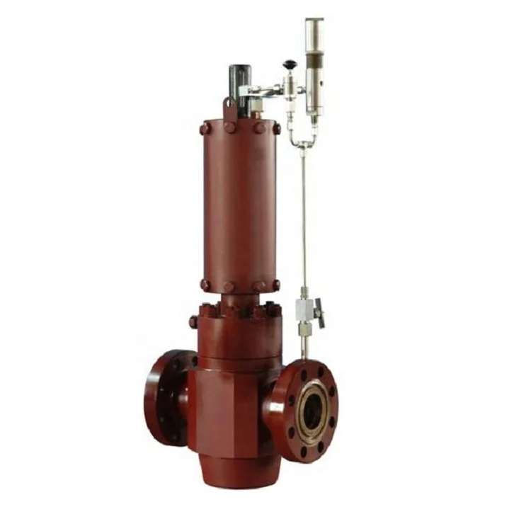
Surface safety valve (SSV) is a hydraulically actuated fail-safe gate valvefor producing or testing oil and gas wells with high flow rates, high pressures, or the presence of H2S.
The SSV is used to quickly shut down the well upstream in the event of overpressure, failure, a leak in downstream equipment, or any other well emergency requiring an immediate shut down.
A number of SSV models are available for different well conditions (pressures, temperatures, and flow rates) and with various connections, such as hammer union or API-6A flanges.
Subsurface safety valves (SSSVs), which are standard and often statutorily required in the oil and gas industry for upper completions, were first developed in the late 1930s. Operators sought to drill more high-pressure wells, often near populated areas or, conversely, offshore or very isolated areas, making the need for a device to protect the wells from uncontrolled flow increasingly apparent. The need was made even more urgent by the fact that the uncontrolled flow could be caused by accident or by damage to the surface equipment, which at the time was quite common.
By the 1970s three companies had established themselves as industry leaders as SSSV suppliers in the field: Otis Engineering (now Halliburton), Baker Hughes (now Baker Hughes, a GE company) and Camco Products and Services (now Schlumberger). Implementation of SSSVs grew, but it was not until the Piper Alpha incident of the late 1980s that regulations truly shifted. The explosion on Piper Alpha and resulting oil and gas fires that destroyed the platform served as the impetus for global regulatory mandates that SSSVs be deployed in offshore wells.
The watchword for the 21st century oil industry has been reliability, as offshore, deepwater workovers in many wells cost tens of millions of dollars. As such, reliability became the primary focus and mission of the engineering team at Tejas Research & Engineering as it moved to design and deliver reliable, high-performing products. In the late 2000s the energy industry and governments worldwide revisited the use of SSSV deployment requirements, which had not seen much change since the Piper Alpha incident more than two decades prior. The consensus was that when reliable SSSVs are present, a blowout and oil spill are virtually impossible. Therefore, many governments, such as the EU, now require SSSVs in all wells—even those on land.
Modern developments in SSSV design have sought to address the industry’s challenges and the issues that arise in more complex reservoirs and harsher downhole environments through additional testing and research to optimize the valves’ technical specifications. While the basic functionality of the valves has not changed for some time, the standard to which the valves are engineered and manufactured is now shifting, thanks in part to a new partnership between Tejas Research & Engineering and National Oilwell Varco (NOV). It is a partnership bolstered by Tejas’ involvement on the American Petroleum Institute’s (API) 14A standards subcommittee.
NOV has built its portfolio of completion and production products and technologies since the company’s acquisition of Trican Well Service’s completion tools division in mid-2016. As the breadth of NOV’s completions business expanded to include multistage fracturing and multizone completions, among other disciplines, it became clear that a missing link for upper completions was SSSVs. The company partnered with Tejas Research & Engineering to commercialize a line of SSSVs representing a new industry standard in design and reliability.
Tejas Research & Engineering sprang from the Camco tradition that pioneered many pivotal developments in SSSV design. The R&D and engineering for safety valve products are conducted in Tejas’ HP/HT facility in The Woodlands, Texas, where SSSVs with pressure requirements of 25,000 psi and 260 C (500 F) are designed, tested, qualified and produced.
Tejas’ model TRSV(E) SSSVs are tubing-retrievable, surface- controlled, normally closed devices installed in oil and gas wells to control tubing fl ow. Metal-to-metal seals are used in 100% of Tejas’ tubing-retrievable product line, which has products that are rated to 10,000 psig and are suitable for temperatures up to 176 C (349 F) at moderate setting depths. Higher temperature/pressure/setting depths/slimline diameters are available for custom order. The TRSSSV series are API-14A V1 certified and adaptable to any standard or premium tubing thread. The system features a large fullbore, where the inside diameter (ID) is equivalent or greater tubing than the tubing ID to which the SSSV is attached. Additionally, it has either flat flappers (2⅜ in. to 3½ in.) or curved flappers (4½ in. to 7 in.) and a single rod piston featuring nonelastomeric dynamic seals. The TRSSSV is available in either equalizing or nonequalizing trims. The valve is controlled hydraulically with a ¼-in. control line in the well’s annulus, enabling valve closure during an emergency shutdown.
The new safety valve builds upon lessons learned in valve design over Tejas Research & Engineering’s entire history. Previous valves have achieved significant milestones— including one design that has more than 8,000 valves in use without a single failure or degradation in performance. Completions have evolved since those early designs, and new valves need to withstand significantly higher temperatures, working pressures and setting depths as well as accommodate different diameters. The new valve product line meets the rigorous quality standards outlined in API Specification 14A and tested beyond the specifications in Revision 12, including Annex H, which specifically addresses the verification and validation requirements for use in HP/HT environments.
An evolution in safety valve standards means the industry can be more confident that well control incidents will not occur. As regulations continue to change and become stricter, it is imperative that safety valves maintain their rigorous quality and durability while being able to handle even more challenging well environments.
Production sustainability from oil and gas wells could be an uphill task when there is a need to constantly monitor Subsurface safety valves for optimal functionality. It"s always a standard practice that surface safety valves are tested on specific periods safe enough to ensure well"s safety is not compromised. Surface controlled subsurface safety valves are also tested with same objective.
Many Production Engineers are ignorant of the fact that the subsurface safety valve affect well productivity through drop in hydrostatic pressure across valve for Surface Controlled Subsurface Safety Valve (SCSSV) and the Sub-Surface Controlled Subsurface Safety Valves (SSCSV) additionally causes drop in fluid flow across valves in the process of sensing fluid velocity across valve.
In this Paper, A case by case analysis was performed on the various sub-surface safety valves for producing wells with the view of minimizing friction to flow of well fluids which affects performance which in turn minimizes production restriction. Efficiency of different type of subsurface safety valves where evaluated and compared and business cases where made on the most attractive option.
Periodic testing or inspection of valves was analyzed, and best routine testing time proffered with reasons to wells performance. The advantages and disadvantage of different valve options were also discussed to recommend a workable valve option for Uninterrupted well flow. Flow assurance and flow stability considerations were also made to ensure no unwanted valve closure occurs.
A Stable and uninterrupted production was realized for five wells using this analytical method and the total productivity increase was about 1,200 BOPD for the five wells. Addressed wax blockage valve/sticky flapper problems to enable the SCSSV four wells function. The SSCSV of the last well caused flow assurance challenges which was addressed by surface choke bean optimization.

United States Patent 11 1 A Young AMBIENT PRESSURE RESPONSlVE SAFETY VALVE l PM i /3a on 3,814,181 1451 June 4, 1974 Primary Examiner-James A, Leppink Attorney, Agent, or Firm-David L. Moseley; Stewart F. Moore; William R. Sherman [57] ABSTRACT A safety valve apparatus for wells producing well fluid by formation pressure and including a valve mechanism that is normally maintained in the open or flowing position by an urging means and is closed responsive to a predetermined differential pressure developed between flowing pressure, within the valve apparatus and ambient pressure, externally of the valve apparatus. A predetermined differential pressure develops a force overcoming the bias of the urging means and moves the valve mechanism to the closed position thereof. The valve apparatus is provided with means for modifying the effective size of the inlet orifice of the valve mechanism responsive to a predetermined decrease in ambient pressure from a normal operating range, thereby developing the predetermined pressure differential for achieving automatic closure of the safety valve apparatus.
AMBIENT PRESSURE RESPONSIVE SAFETY VALVE FIELD OF THE INVENTION This invention relates generally to safety valve apparatus for downhole environment in wells having a formation pressure for producing well fluid, and more specifically concerns the provision of a safety valve apparatus adapted for positive closure of a safety valve mechanism in the event ambient pressure at the level of the safety valve should decrease below a predetermined minimum.
BACKGROUND OF THE INVENTION In the early stages of development of the petroleum industry it was typically the practice to tap a pressurized source or reservoir of petroleum products by drilling and to allow any gas pressure that might be contained therein to dissipate to a controllable level or to a level at which the petroleum products might be recovered by pumping. The gas during this particular period was substantially unusable and wasgenerally wasted. Where oil was blown fromthe well along with the escaping gas, it was the practice to collect the oil in surface ditches constructed about the well site. As the petroleum industry rapidly developed, it was discovered that the pressurized gas within production formations could be efficiently utilized to produce other petroleum products contained therein and the gas itself could be efficiently marketed in its natural state or in other physical states, such as the liquid state, for example. Various developments have been made to ensure against the loss of gas pressure within petroleum reservoirs, but most of the early developments were related to surface control valves and the like that might be manipulated manually or mechanically for flow control purposes.
Although wells may now be effectively controlled to prevent unnecessary escape of gas from the reservoir, occasionally an unforeseen circumstance will develop that may cause a well to blow wild. Surface production control equipment may be damaged by mechanical apparatus operating in the vicinity of the well site and the surface equipment of the well may be otherwise subject to various hazards of the surface environment that could result in blow-out of the well.
When the well is being produced through an offshore facility such as a production platform, the occurrence of an explosion or fire and the like is extremely hazardous to lives of personnel because of the difficulty of escape from the production facility. Offshore explosions and fires are also extremely expensive from a property damage standpoint because of the extremely expensive nature of offshore production facilities. Moreover, an oil spill that might be caused by damage to surface production flow control equipment, located on an offshore production facility, may result in pollution of an extremely large area of the shoreline thereby resulting in extensive. damage to wildlife sanctuaries and the like.
Explosions, both at surface flow control equipment and within the well bore below the surface equipment, may result in sufficient damage to allow a"particular well to blow wild.
Wells may also blow-out due to shifting of earth stratum through which the well bore passes and likewise, may blow-out due to insufficient structural interconnection between well cement within the well bore and the earth stratum through which the well bore passes,
When a well blows wild for any reason whatever, the expense thereof to well drilling and producing companies can be extremely great. Such expense may be caused by loss of production during the time the well is blowing wild and due to the loss of field reservoir pressure which may prevent future production of petroleum products in situ. Loss of reservoir pressure may also substantially slow the production of petroleum products or may make the production of such products extremely expensive by requiring gas lifting operations and secondary recovery operations for effective production.
It is obviously necessary to provide subsurface production flow control mechanisms that may be controllable automatically or selectively as desired to prevent well blow-outs even though surface flow control equipment may be damaged or rendered inoperative. Subsurface production flow control apparatus of this nature may be capable of preventing explosion and fires that otherwise might occur in the event of damage or malfunction that surface flow control systems. Moreover, subsurface flow control safety equipment may effectively prevent the pollution of the surface environment tha might otherwise occur if an offshore well is allowed to blow wild. Since subsurface safety valve mechanisms may effectively present a great majority of well blow-outs and since pollution control is so extremely important from the standpoint of conservation, it is obvious that subsurface safety mechanisms are necessary to efficient functioning of the petroleum industry.
THE PRIOR ART Various well safety systems have been developed, involving both surface and subsurface safety equipment, that may be actuated to a safe position in response to the development of an adverse well condition, to stop the flow of production fluid, until the production equipment may be made safe for further operation. Actuation of safety valves may be automatically controlled by pilot mechanisms, responsive to remote sensing, or in the alternative, safety valves may be actuated to the safe position by a force developed responsive to an adverse well condition. Offshore wells may include production equipment provided with a safe-mode that may allow production of the well or may cause the well to shut in the event of storms or other hazardous conditions that might otherwise adversely affect production operations.
Surface and subsurface safety valve equipment may be developed that effectively achieves shut-in of surface or subsurface production flow control equipment to terminate the flow of production fluid in the event excessive well pressures should develop and in the event the flow control equipment may be subjected to excessive flow of production fluid. For the most part, presently available downhole safety valve equipment is solely velocity sensitive and remains open to allow the flow of production fluid during periods of normal or low velocity flow. Such valves are typically actuated by forces developed during high velocity flow to move the valve structure to the closed position and stop the flow of production fluid.
Where a well is being produced and a failure occurs in the production system of the well, it is desirable that the well shut in automatically. One typical device for serving this purpose is a so-called velocity sensitive valve that includes a spring operator piston which is sealingly slidable within a housing and carries a flow restriction, typically referred to as a flow bean, through which the flowing well fl-uid passes. The pressure drop across the restriction of the flow bean acts on an area defined generally by the piston seal diameter and the bore diameter of the flow restriction to produce an upward resultant force that is related to the flow rate or velocity. When the flow rate increases to a value sufficient to compress the spring by a predetermined amount, the valve closes to shut off the flow.
One of the more commonly employed valve elements is a poppet valve device that includes an enlarged head around which the flowing fluid passes immediately before it flows through lateral ports in the valve actuator sleeve. ln"the closed position, the head engages an annular valve seat with a metalto-metal seal. This type of closure presents a number of difficulties, however. It is likely to leak where there are small manufacturing imperfections in the respective seal surfaces. Abrasives such as sand grains in the well fluids, scale and the like, tends to erode away the metal seat and cause a tiny leak which, in very short order, may be enlarged by cavitation and result in the failure of the valve. Moreover, if the valve element does not movedirectly into a tight sealing position and is allowed to oscillate or to develop a throttling function for any period of time before closing, the throttling condition will likely result in cavitation of the sealing parts, thereby rendering the valve inoperative.
Another commonly employed valve system utilizes a vall valve element, where closure is effected by metalto-metal contact between the ball and a companion seat or by a bonded seal ring that seats against the metal surface of the ball. A condition of throttling can occur if the valve ball is not moved directly and firmly to its fully closed position upon immediate sensing of If a leak should occur in the surface flow equipment of the well, and" if the leak is initially small and increases due to erosion or cavitation of the flow control equipment, the differential pressure condition that causes automatic closure in a velocity sensitive well safety system may cause a throttling condition to occur and, therefore, may cause cavitation of the safety valve mechanism, rendering the safety valve inoperable. It is, therefore, a primary object of the present invention to provide a novel safety valve mechanism that is capable of closure responsive to a predetermined pressure differential but is not subject to erosion by well fluid due to the development of a throttling condition.
It is an even further object of the present invention to provide a novel safety valve mechanism capable of moving directly and efficiently into closed position responsive to the sensing of an adverse well condition that might otherwise develop excessive flow in a well production system.
Among the several objects of the present invention is noted the contemplation of a novel downhole safety valve mechanism for a well that is responsive to a predetermined decrease in ambient pressure in a well bore externally of a safety valve mechanism for developing a pressure drop that causes closure of the safety valve.
it is an even further object of the present invention to provide a novel safety valve mechanism for a downhole well environment including means, separate from the valve mechanism, that functions to develop a pres- Another important object of the present invention contemplates the provision of a novel safety valve mechanism that"may be reopened simply by injection of sufficient pressure into the tubing string to balance the forces maintaining the closed valve assembly in its closed condition.
This invention also contemplatesthe provision of a novel downhole safety valve mechanism that is of inexpensive nature, is reliable in use and low in cost.
BRIEF SUMMARY OF THE INVENTION A downhole safety valve mechanism, according to the present invention, may include a housing structure adapted for connection to a production tubing within a well system within which housing may be disposed a safety valve assembly capable of terminating the flow of production fluid responsive to the development of an adverse pressure condition within the well. A valve seat may be provided within the housing against which may be seated a valve element that is movable between open and closed positions relative to the seat. The valve element may be connected to an actuating sleeve movably disposed within the housing and urged to the open position thereof by a spring element to allow flow of fluid through the valve mechanism. The movable sleeve may constitute a piston against which a force is developed by differential pressure to cause closure of the valve element, the pressuredifferential being defined.
by the difference in flowing pressure within a flow passage defined in the sleeve and ambient pressure within the well bore externally of the safety valve mechanism.
Sufiicient pressure differential may be developed to cause automatic closure of the safety valve mechanism responsive to a predetermined decrease in ambient pressure that causes a movable element to modify the effective size of the inlet opening of the valve mechanism in direct proportion to the amount of decrease in ambient pressure. A plunger, carried by a pressure dome portion of the valve housing, and movable responsive to pressure differential developed between ambient pressure and pressure within a variable volume gas charged chamber, functions to restrict the effective size of the inlet opening of the valve if excessive flow of production fluid through the valve structure, which might be caused by failure of surface equipment, decreases ambient pressure within the well bore below a predetermined minimum operating level. The plunger causes a pressure differential to occur at the inlet opening of the valve assembly to which pressure differential, the actuating sleeve is responsive to move the valve element to the closed condition thereof. An urging means such as a compression spring may be utilized to assist movement of the plunger element towarda position restricting the effective size of the inlet opening.
BRIEF DESCRIPTION OF THE DRAWINGS So that the manner in which the above recited features, advantages and objects of the present invention, as well as others, which will become apparent, are attained and can be understood in detail, more particular description of the invention, briefly summarized above, may be had be reference to the embodiment thereof which is illustrated in the appended drawings, which drawings form a part of this specification.
" FIG. I is a pictorial representation, illustrated partially in section, of a subsurface earth formation having a well bore extended therethrough and being lined with a well casing enclosing a production tubing, to which production tubing is attached a downhole safety valve mechanism constructed in accordance with the present invention.
FIGS. 2A, 2B and 2C are longitudinal sectional views forming the upper intermediate and lower portions, respectively, of a safety valve mechanism constructed in accordance with the present invention.
FIG. 3B is an enlarged cross-sectional view of an ambient pressure responsive valve inlet opening controller constructed in accordance with the present invention.
DESCRIPTION OF THE PREFERRED EMBODIMENT Now referring to the drawings and first to FIG. "1, an earth formation is illustrated generally at having a well bore 12 drilled therein which bore is lined with a well conduit 14 that may be cemented in place in conventional manner and traverses the earth formation being produced. A production string of tubing 16 extends from the surface downwardly through a typical production packer 18 having a packing element 20 that seals off the production interval from the well casing thereabove. Well fluid enters the casing 14 through perforations (not shown) disposed below the packer l8 and passes upwardly through the tubing string 16.
" At a suitable downhole location in the tubing string, usually above the packer 18, a safety valve 22, constructed in accordance with the present invention, is shown to be attached to the lower extremity of a conventional wire line setting a retrieving mandrel 24 that is seated in a landing nipple 26. The retrieving mandrel 24 is provided with locking dogs 28 and locator keys 30, disposed on either side of seal packing rings 32, and the upper extremity of the mandrel 24 is provided with a running and retrieving neck 34. The details of construction of the setting mandrel assembly, as well as the procedures for running and retrieving the assembly on wire line, are well known to those skilled in the art and form no part of the present invention.
22, a valve housing, generally illustrated at 36, may comprise an upper sub 38 having an internally threaded upper extremity 40 for establishing threaded connection with the lower extremity of the setting mandrel 24.
The housing 36 of the safety valve may also be provided with a valve section 56, provided with internal threads 58 at the upper extremity thereof for threaded connection to a lower externally threaded portion 60 of the lower housing section 44. The valve section may also be provided with internal threads 62 at the lower extremity thereof for connection to the upper externally threaded portion 64 ofa support coupling 66. The lower extremity of the lower housing section 44 may define an annular abutment 68 providing support for a seat element 70 that is retained in engagement with the abutment surface 68 by an annular seat support flange 72 defined within the valve section 56 of the housing. The seat element 70 may be provided with a sealing element 74, such as an O-ring or the like, retained within a circumferential groove for establishment for a sealed relationship between the seat element 70 and the internal wall 76 of the seal pocket defined between the abutment shoulder 68 and the internal fiange 72. The seat ring 70 presents an inclined stop surface 78 located just above an inwardly facing sea] surface 80.
A valve element, illustrated generally at 82, may be disposed for reciprocation within the valve section 56 of the housing and may include a tubular portion 84 provided with an upper threaded extremity 86 for threaded connection to a lower internally threaded portion 88 of a valve actuating sleeve element 90, also disposed for reciprocation within the housing 36. The tubular portion 84 of the valve element may be provided with a closed lower extremity 92 which may be stepped down to define an annular abutment portion 94 providing support for an annular seal retainer ring 96. A sea] support end cap 98 may be provided with internal threads 100 for threaded connection with external threads 102 of the valve element, and together with the retainer ring 96 may serve to retain an annular sealing element 104 that may be compressed to some degree by the retainer ring or compression ring 96 to increase the degree of sealing engagement between the sealing element 104 and the seal surface 80, when the valve element is in its closed position.
As the valve element 82 is moved upwardly to its closed position, the outer periphery of the sealing element 104 will slide into sealing engagement with the generally cylindrical sealing surface 80 of the seal element 70 and a tapered surface 106 of the compression ring 96 ,will move into abutment with the tapered sur face 78 of the seat element. As the valve element 82 is urged by pressure differential in an upwardly direction, the compression ring 96 will be forced away from the abutment portion 94 and will deform the sealing element 104, thereby causing the sealing element to increase the pressure of its sealing contact with the annular sealing surface 80. The sealing ability of the valve is therefore increased directly proportional to increase in pressure differential across the closed valve.
In the open position of the valve element 82, as shown in FIG. 2B, fluid being produced through the safety valve mechanism will flow around the lower extremity of the valve element and will enter the tubular portion 84 through at least one and preferably a plurality of apertures 108. The production fluid will then continue upwardly through a flow passage 110 defined by cooperating tubular portions of the valve element and valve actuating sleeve and into the tubing string to which the safety valve mechanism is connected by the upper sub 38.
It will be desirable to provide a mechanism for retaining the valve element 82 in the open or H6. 28 position thereof as long as ambient pressure within the well casing and externally of the safety valve mechanism is within a proper operating range and to achieve closure of the valve element to stop the flow of production fluid in the event ambient pressure should fall below a pre determined minimum level for any reason whatever. Means for achieving pressure responsive control on the valve element 82 may conveniently take the form illustrated in FIG. 2A where an urging means, such as a compression spring 112 may be interposed between abutment shoulders 114 and 116 defined respectively by the lower extremities of the coupling 46 and by a thickened wall portion 120 of the valve actuating sleeve element 90. The compression spring 112, under normal conditions, will urge the valve actuating sleeve element 90 downwardly until an annular tapered shoulder 122, defined thereon, moves into abutment with a tapered support shoulder 124, defined internally of the lower housing section 44 where further downward movement of the valve element 82 will be restrained by the stop surface 124.
It will be necessary to develop a force, acting upwardly on the valve actuating sleeve 90, that is capable of overcoming the bias of the compression spring 112 in order to cause upward movement of the actuating sleeve to a position moving the valve element to its closed position. In accordance with the present invention, an annular sealing element 126 may be retained within an annular groove defined within an inwardly projecting portion 128 of the coupling element 46, which sealing element may establish sealing contact with a generally cylindrical sealing surface 130 defined on the valve actuating sleeve 90. A second annular sealing element 32 may be retained within an annular groove defined in a piston element 134 having a lower internally threaded extremity 136. receiving external threads 138 defined at the upper extremity of the sleeve element 90. The sealing element 132 may be disposed in sealing engagement with an internal sealing surface 140 defined within the upper housing section 42. The piston element 134,-together with the sleeve and sealing element 132, cooperate with the upper housing section 42, the coupling element 46 and sealing element 126 to define a valve actuating chamber 142 that is communicated with ambient pressure by at least one and preferably a plurality of orifices 144 formed in the upper housing section 42. Above the piston element 134 may be provided a thin walled sleeve cooperating with a sleeve 137 depending from the upper sub 38 to define a barrier for sand and other abrasive matter produced along with the well fluid. The sleeves 135 and 137 define a dead space therebetween that prevents sand from accumulating above the O-ring seal 132, thereby protecting the seal from abrasive wear.
. Ambient pressure, communicated through orifices 144 into the annular valve actuating chamber 142, will act upon"a surface area of the valve actuating sleeve element 90 defined by the piston element 134, and referred to as area Al, while fluid pressure within the valve housing downstream of the valve element, also referred to as flowing pressure, acts upon a surface area of the valve actuating sleeve referred to as A2. Under normal operating conditions ambient pressure acting upwardly upon the sleeve 90 will be slightly overbalanced by flowing pressure acting downwardly upon the sleeve and the net downward pressure responsive force will be added to the downward force developed by the compression spring 112, thereby maintaining the sleeve, and the valve element connected thereto, in the lowermost or open position thereof. If, for some reason, the pressure of the flowing fluid within the valve mechanism should decrease substantially relative to ambient pressure externally of the safety valve, the differential pressure acting upon the sleeve 90 will be such that a resultant force of substantial magnitude will be developed acting upwardly upon the sleeve 90 through the piston element 134 that overcomes the compression of spring 112 and urges the valve actuating sleeve 90 to the upper position thereof, thereby causing the valve element 82 to seat against the seat element 70 and stop the flow of fluid through the apertures 108.
If the flow control equipment of a well should be come damaged, such as by rupture of a flow line, failure of a well control valve, etc. and uncontrolled flow of well fluid is allowed to occur, the pressure of flowing means for achieving valve closure, where the valve is v actuated to the closed position thereof by a condition of predetermined pressure differential, may conveniently take the form illustrated particularly in FIG. 2C where a combination inlet adapter and support sleeve 146 is shown to be provided with upper and lower internally threaded extremities 148 and 150, respectively, for connection to externally threaded portions 152 of coupling element 66 and 154 of a coupling element 156. The coupling element 156, in turn, may be provided with an externally threaded lower portion 158 adapted to receive internal threads 160 defined within the upper extremity of a pressure dome housing 162. The housing 162 may be closed at its lower extremity by a closure plug 164 having an externally threaded portion 166 disposed in threadedconnection with the lower internally threaded portion 168 of the housing 162. The closure plug 164 cooperates with the housing 162 and coupling element 156 to define an internal pressure chamber or dome, within which may be introduced a gaseous medium at any suitable pressure, depending upon the desired operational characteristics of the safety valve mechanism.
It may be desirable to add, to the force created by the compressed gaseous medium acting upon the plunger, a mechanical force such as might be developed by a compression spring 208 or any other suitable urging means to develop a resultant force tending to urge an enlarged head portion 210 of the plunger into restricting relation with an inlet aperture 212 in the coupling element 66 to restrict the flow of production fluid through the coupling passage 114 and into the safety valve mechanism. The combined forces of gas pressure and the spring force acting upon the plunger, during normal operation of the safety valve mechanism, are overcome by a resultant downward force, acting upon the plunger, that is developed by ambient pressure and maintains the plunger in its FIG. 2C position thereof until ambient pressure decreases below a predetermined minimum level. The pressurized medium within the pressure chamber or dome 170 is always maintained at a lower pressure than the ambient pressure expected during normal operation of the flow system of the well and the combined forces developed by the gas eous medium within the pressure chamber and the force developed by the compression spring will be less than the downward force developed by ambient pressure during normal valve operation.
As an illustration of the foregoing, the pressure of the compressible medium in the pressure dome may be designated P while the pressure of production fluid flowing through the safety valve mechanism may be P;, the force exerted by the compression spring in the pressure dome may be P and ambient pressure may be designated P During normal operation of the flow system of the well P P is less than P and, therefore, the plunger will be retained in its lowermost position by the resultant force acting on the plunger and the inlet aperture 212 will be unrestricted. Also during normal operation of the flow system, P, will be less than P and the valve actuating mechanism will be maintained in the open position thereof by the resultant force created by pressure differential between P; and P,,.
When an adverse well condition is developed, due to failure of the flow system that would otherwise cause excessive flow to occur in the well flow system, P, will suddenly decrease and this pressure decrease will be reflected by a decrease in the ambient pressure P,, of the well. When this occurs P P, will exert a force on the plunger that is greater than the opposing force caused by ambient pressure P,, acting on the plunger and the resultant force between these two opposing forces will cause the plunger to be moved upwardly causing the head portion of the plunger to restrict the inlet opening 212. This will cause a pressure differential to be created across the inlet aperture between am-" bient pressure P,, and flowing pressure P, which pressure differential will develop a resultant force acting on the piston 134 of the valve actuating sleeve element which urges the sleeve and the valve element 82 to the closed position thereof.
OPERATION Assuming the safety valve mechanism of this invention to be connected to a tubing string in conventional manner and also assuming it to be disposed in the flowing condition thereof as shown in FIGS. 2A, 2B, 2C, 3A and 33, production fluid will be entering the safety valve mechanism through the inlet slots 113 and will be flowing through the inlet aperture 212 and inlet passage 114 into the tubular valve housing and will flow through inlet apertures 108 into the flow passage 110 defined by the valve actuating sleeve element 90. The compression spring 112 will develop a force acting downwardly upon the annular shoulder 116 of the valve actuating sleeve and will overbalance a force developed by ambient pressure within the valve actuating chamber 142 acting upwardly upon the piston portion 134 of the sleeve element, thereby resulting in a net downward force which maintains the sleeve in its lowermost position against the tapered stop shoulder 124. Under this condition the valve element will be open and production fluid will be produced in unrestricted manner through the safety"valve mechanism and the tubing string. The flow of production fluid will be controlled elsewhere in the flow system, such as by a choke disposed in the surface flow control equipment.
If a failure occurs in the production system of the well and a substantial decrease in flowing pressure occurs, this decrease will be reflected through the safety valve mechanism thereby resulting in a decrease in ambient pressure within the well casing. As ambient pressure decreases, the net downward force acting upon the plunger 194 will be reduced and perhaps will be dissipated, thereby resulting in a net upward force acting upon the plunger due to the combined effects of the spring force and gas pressure force exerted upon the plunger from within the pressure chamber 170. When this occurs, the plunger will begin to move upwardly causing the head portion of the plunger to move into restricting relation with the inlet aperture 212, thereby causing a pressure drop to be developed across the inlet aperture. The pressure drop is of course reflected downstream from the aperture into the flow passage 110 and also causes the development of a greater pressure differential acting across the piston portion 134 of the valve actuating sleeve 90 which reduces the net downward force acting upon the sleeve.
1f ambient pressure should decrease below a predetermined minimum operating level the head portion 210 of the plunger will be caused to move into juxtaposed relation with the inlet aperture 212, thereby developing a severe pressure drop across the inlet aperture 212. This condition causes a severe pressure differential to exist across the piston element 134, due to ambient pressure within the valve actuating chamber 142 acting upwardly on the piston which develops a force of sufficient magnitude to overcome the compression force of spring 112, and thereby urges the valve actuating sleeve 90 upwardly and moves the valve element 82 to its closed position as shown in FIGS. 4A and 4B.
As soon as the valve element 82 moves to its closed position and the sealing element 104 achieves sealing engagement with the sealing surface of the valve seat element 70, flow of production fluidthrough the valve will be stopped and the valve element will remain closed due to the pressure differential acting upon the piston portion-134 of the valve actuating sleeve 90. When the flow of production fluid through the valve is stopped, pressure within the inlet passage 114 upstream of the valve element will quickly become balanced with ambient pressure. Moreover, because the valve element 82 has sealed the low pressure condition from the inlet passage, the reduced pressure condition will no longer be reflected below the safety valve. Ambient pressure within the well, therefore, will suddenly increase to the maximum well pressure and the increased ambient pressure, acting upon the plunger 194, will again develop a net downward force that will urge the plunger to the lowermost position thereof.
When it is desired to reopen the safety valve mechanism, after the production system of the well has been restored to proper operating condition, a pressurized medium may be injected into the tubing string above or downstream of the valve and, acting upon surface area A2 will develop a force which, when added to the force developed by compression spring 112, will overcome the force developed by ambient pressure acting on area A1 of the piston. A downward resultant force is thereby produced that will move the actuating sleeve and the valve element to the open position thereof, as shown in FIG. 2A. At this time, ambient pressure will be at its highest level and production flow may be initiated simply by bleeding off the injected pressure, such as by opening ofa surface flow control valve of the well production system.
The safety valve mechanism of this invention provides a valve mechanism that will remain open, allowing normal unrestricted flow of production fluid as long as ambient pressure within the well remains within a predetermined operating range. A mechanism is provided for closure of the safety valve assembly responsive to development of a predetermined decrease in ambient pressure and means is also provided for developing a pressure differential capable of actuating the valve assembly to-its closed position responsive to decrease in ambient pressure below a predetermined minimum pressure level. During normal operating conditions, the valve actuating sleeve and valve assembly of the present invention will be maintained in a static position and will not be allowed to reciprocate as is typically the case where a safety valve mechanism is maintained in its open position by force developed solely by pressure differential across a restriction provided in the flow path through the valve mechanism.
After becoming automatically closed responsive to predetermined decrease in ambient pressure, the valve assembly may be reopened and placed back in production by simple injection of pressure into the tubing string above the valve.
.Since the valve closes automatically, responsive to decrease in ambient pressure below a predetermined operating level, the valve may be effectively tested simply by opening a surface control valve sufficiently to increase production flow and thereby reflect a predetermined decrease in pressure into the well casing. The valve will shut in as soon as ambient pressure decreases to a level allowing the plunger 194 to be urged, by the combined forces of the compression spring 208 and the fluid pressure within the pressure chamber 170, into restricting relation with the inlet aperture 112. If, during inspection or testing, the valve mechanism is found to be in need of servicing, the valve mechanism may be removed from the flow control system of the well without necessitating removal of the tubing string. A conventional wire line tool may be utilized to retrieve and replace the safety valve mechanism.
It is therefore seen that this invention is one well adapted to attain all of the objects and advantages, hereinabove set forth, together with other advantages,
valve means being supported by a well tubing and including co-engageable means being movable between open and closed positions responsive to a pressure differential of a predetermined magnitude; and
flow restriction means being disposed upstream of said valve means and being responsive to a decrease in ambient pressure in the well bore for developing said pressure differential.
valve housing means adapted for connection to the production tubing of said well, said housing means having inlet and outlet aperture means communieating said valve housing respectively with said casing and said production tubing;
valve actuator piston means being disposed in movable relation to said housing means and being movable relative to said valve housing responsive to predetermined pressure differential between ambient pressure and pressure within said valve housing means, said valve actuator means, upon being moved, inducing opening and closing movement to said valve means; and
flow restricting means being supported within said well casing upstream of said valve means and being responsive to ambient pressure for controlling the flow of production fluid toward said valve means, said flow restricting means developing said predetermined pressure differential responsive to predetermined decrease in ambient pressure.
piston means movable supported by said valve housing means and being movable between a position allowing unrestricted flow of fluid through said inlet aperture means and positions restricting the flow of fluid through said inlet aperture means; means urging said piston means toward said positions restricting the flow of fluid through said inlet aperture means; and ambient pressure acting upon said piston means and developing a force opposing said urging means and maintaining said piston means in the said position allowing unrestricted flow of fluid.
housing means adapted for connection to the production tubing of a well having formation pressure for producing the well, said housing means deflning.
valve means movably disposed within said housing and being movable between open and closed positions relative to said seat means for controlling the flow of fluid through said flow passage means;
piston means being carried by said valve means and being movable within said housing responsive to predetermined pressure differential between ambient pressure and pressure downstream of said valve means for moving said valve means to the closed position thereof against the bias of said urging means; and
flow restricting means being supported within said casing upstream of said valve means and being responsive to ambient pressure for controlling the flow of production fluid toward said valve means, said flow restricting means developing said pressure differential responsive to a predetermined decrease in ambient pressure.


 8613371530291