
safe working load of wire rope sling in stock

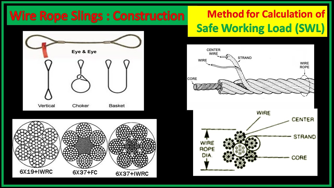
Wire rope is often used in slings because of its strength, durability, abrasion resistance and ability to conform to the shape of the loads on which it is used. In addition, wire rope slings are able to lift hot materials.
Wire rope used in slings can be made of ropes with either Independent Wire Rope Core (IWRC) or a fiber-core. It should be noted that a sling manufactured with a fiber-core is usually more flexible but is less resistant to environmental damage. Conversely, a core that is made of a wire rope strand tends to have greater strength and is more resistant to heat damage.
Wire rope may be manufactured using different rope lays. The lay of a wire rope describes the direction the wires and strands are twisted during the construction of the rope. Most wire rope is right lay, regular lay. This type of rope has the widest range of applications. Wire rope slings may be made of other wire rope lays at the recommendation of the sling manufacturer or a qualified person.
Wire rope slings are made from various grades of wire rope, but the most common grades in use are Extra Improved Plow Steel (EIPS) and Extra Extra Improved Plow Steel (EEIPS). These wire ropes are manufactured and tested in accordance with ASTM guidelines. If other grades of wire rope are used, use them in accordance with the manufacturer"s recommendations and guidance.
When selecting a wire rope sling to give the best service, consider four characteristics: strength, ability to bend without distortion, ability to withstand abrasive wear, and ability to withstand abuse.
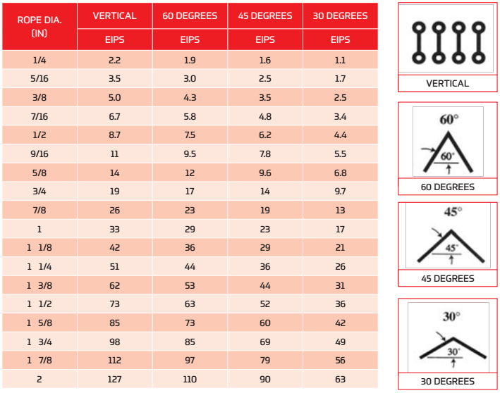
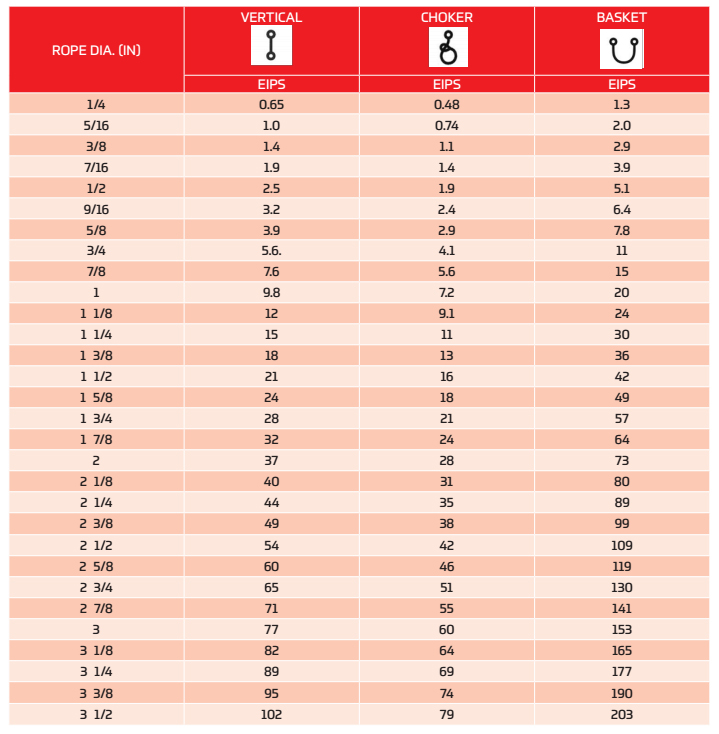
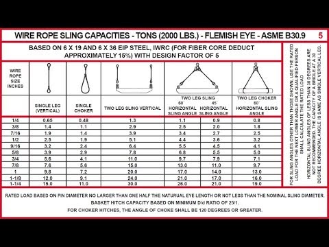
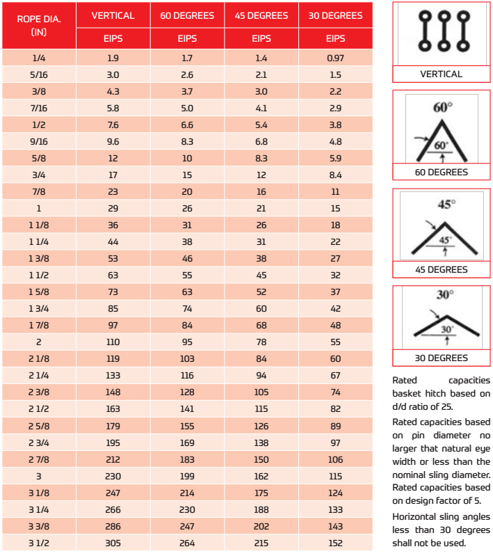
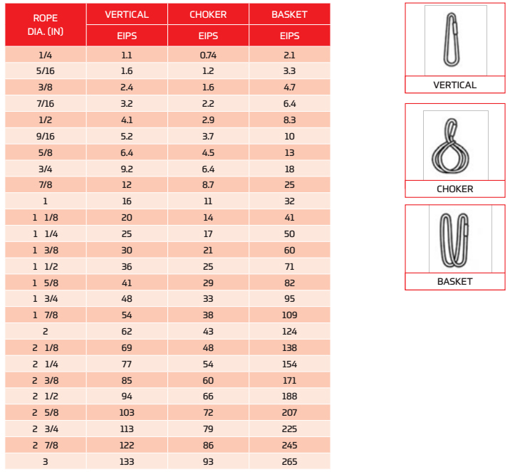
Rated loads (capacities) for single-leg vertical, choker, basket hitches, and two-, three-, and four-leg bridle slings for specific grades of wire rope slings are as shown in Tables 7 through 15.
Rated loads for a sling in a choker hitch are the values shown in Table 7, 9, 11, 13, 14, or 15, provided that the angle of the choke is 120 degrees or more (Fig. 2). Use the values in Fig. 2 or those from the sling manufacturer or a qualified person for angles of choke less than 120 degrees.
Ensure that slings made of rope with 6×19 and 6x37 classifications and cable slings have a minimum clear length of rope 10 times the component rope diameter between splices, sleeves, or end fittings unless approved by a qualified person,
Ensure that braided slings have a minimum clear length of rope 40 times the component rope diameter between the loops or end fittings unless approved by a qualified person,
Ensure that grommets and endless slings have a minimum circumferential length of 96 times the body diameter of the grommet or endless sling unless approved by a qualified person, and
Perform welding of handles or other accessories to end attachments, except covers to thimbles, before assembly of the sling. Ensure that welded end attachments are proof tested by the manufacturer or a qualified person. Retain the certificates of proof test and make them available for examination.
Do not use wire rope clips to fabricate wire rope slings, except where the application precludes the use of prefabricated slings and where the sling is designed for the specific application by a qualified person,
Although OSHA"s sling standard does not require you to make and maintain records of inspections, the ASME standard contains provisions on inspection records.[3]
Use damaged slings only after they are repaired, reconditioned, and proof tested by the sling manufacturer or a qualified person using the following criteria:
Ensure that wire rope slings have suitable characteristics for the type of load, hitch, and environment in which they will be used and that they are not used with loads in excess of the rated load capacities described in the appropriate tables. When D/d ratios (Fig. 4) are smaller than those listed in the tables, consult the sling manufacturer. Follow other safe operating practices, including:
Ensure that multiple-leg slings are selected according to Tables 7 through 15 when used at the specific angles given in the tables. Ensure that operations at other angles are limited to the rated load of the next lower angle given in the tables or calculated by a qualified person,
When D/d ratios (see Fig. 6) smaller than those cited in the tables are necessary, ensure that the rated load of the sling is decreased. Consult the sling manufacturer for specific data or refer to the WRTB (Wire Rope Technical Board) Wire Rope Sling Users Manual, and
Ensure that all portions of the human body are kept away from the areas between the sling and the load and between the sling and the crane or hoist hook,
When using a basket hitch, ensure that the legs of the sling contain or support the load from the sides, above the center of gravity, so that the load remains under control,
Ensure that the load applied to the hook is centered in the base (bowl) of the hook to prevent point loading on the hook, unless the hook is designed for point loading,
Before initial use, ensure that all new swaged-socket, poured-socket, turnback-eye, mechanical joint grommets, and endless wire rope slings are proof tested by the sling manufacturer or a qualified person.
Permanently remove from service fiber-core wire rope slings of any grade if they are exposed to temperatures in excess of 180 degrees F (82 degrees C).
Follow the recommendations of the sling manufacturer when you use metallic-core wire rope slings of any grade at temperatures above 400 degrees F (204 degrees C) or below minus 40 degrees F (minus 40 degrees C).
Scope. This section applies to slings used in conjunction with other material handling equipment for the movement of material by hoisting, in employments covered by this part. The types of slings covered are those made from alloy steel chain, wire rope, metal mesh, natural or synthetic fiber rope (conventional three strand construction), and synthetic web (nylon, polyester, and polypropylene).
Definitions. Angle of loading is the inclination of a leg or branch of a sling measured from the horizontal or vertical plane as shown in Fig. N-184-5; provided that an angle of loading of five degrees or less from the vertical may be considered a vertical angle of loading.
Basket hitch is a sling configuration whereby the sling is passed under the load and has both ends, end attachments, eyes or handles on the hook or a single master link.
Cable laid endless sling-mechanical joint is a wire rope sling made endless by joining the ends of a single length of cable laid rope with one or more metallic fittings.
Cable laid grommet-hand tucked is an endless wire rope sling made from one length of rope wrapped six times around a core formed by hand tucking the ends of the rope inside the six wraps.
Cable laid rope sling-mechanical joint is a wire rope sling made from a cable laid rope with eyes fabricated by pressing or swaging one or more metal sleeves over the rope junction.
Choker hitch is a sling configuration with one end of the sling passing under the load and through an end attachment, handle or eye on the other end of the sling.
Equivalent entity is a person or organization (including an employer) which, by possession of equipment, technical knowledge and skills, can perform with equal competence the same repairs and tests as the person or organization with which it is equated.
Female handle (choker) is a handle with a handle eye and a slot of such dimension as to permit passage of a male handle thereby allowing the use of a metal mesh sling in a choker hitch. (See Fig. N-184-1.)
Master link or gathering ring is a forged or welded steel link used to support all members (legs) of an alloy steel chain sling or wire rope sling. (See Fig. N-184-3.)
Diagam howing Two slings with indicators for sling width, overall length, bearing to bearing length, and fabric length. Further indicators point to both male handles, handle eye, female handle, and slot depth
Diagram indicates Forms of Hitch and Kind of Sling. Eye&Eye Vertical Hitch. Eye&Eye Choker Hitch. Eye&Eye Basket Hitch (Alterates have identical load rations). Endless Vertical Hitch. Endless Choker Hitch. Endless Basket Hitch (Alternateve have identical load ratings). Notes: Angles 5 deg or less from the veritcal may be considered vertical angles. For slings with legs more than 5 deg off vertical, the actual angle as shown in Figure N-184-5 must be considered. Explanation of Symbols: Minimum Diameter of Curvature. Represents a contact surface which shall have a diameter of curvature at least double the diameter of the rope from which the sling is made. Represents a contact surface which shall have a diameter of curvature at least 8 times the diameter of the rope. Represents a load in a choker hitch and illustrates the rotary force on the load and/or the slippage of the rope in contact with the load. Diameter of curvature of load surface shall be at least double the diameter of the rope.
Diagram indicates Form of Hitch and Vertical Hitch. Kind of Sling. Eye&Eye Vertical Hitch Not Applicable. Eye&Eye Choker Hitch Not Applicable. Eye&Eye Basket Hitch (Alternates have identical load ratings). Endless Vertical Hitch Not Applicable. Endless Choker Hitch Not Applicable. Endless Basket Hitch (Alternates have identical load ratings). Notes: For vertical angles of 5 deg or less, refer to Figure N-184-4 ""Basic Sling Configurations with Vertical Legs"". See Figure N-184-4 for explanation of symbols.
Proof test is a nondestructive tension test performed by the sling manufacturer or an equivalent entity to verify construction and workmanship of a sling.
Reach is the effective length of an alloy steel chain sling measured from the top bearing surface of the upper terminal component to the bottom bearing surface of the lower terminal component.
Strand laid endless sling-mechanical joint is a wire rope sling made endless from one length of rope with the ends joined by one or more metallic fittings.
Strand laid grommet-hand tucked is an endless wire rope sling made from one length of strand wrapped six times around a core formed by hand tucking the ends of the strand inside the six wraps.
Strand laid rope is a wire rope made with strands (usually six or eight) wrapped around a fiber core, wire strand core, or independent wire rope core (IWRC).
Employers must not load a sling in excess of its recommended safe working load as prescribed by the sling manufacturer on the identification markings permanently affixed to the sling.
Inspections. Each day before being used, the sling and all fastenings and attachments shall be inspected for damage or defects by a competent person designated by the employer. Additional inspections shall be performed during sling use, where service conditions warrant. Damaged or defective slings shall be immediately removed from service.
Hooks, rings, oblong links, pear shaped links, welded or mechanical coupling links or other attachments shall have a rated capacity at least equal to that of the alloy steel chain with which they are used or the sling shall not be used in excess of the rated capacity of the weakest component.
In addition to the inspection required by paragraph (d) of this section, a thorough periodic inspection of alloy steel chain slings in use shall be made on a regular basis, to be determined on the basis of
experience gained on the service life of slings used in similar circumstances. Such inspections shall in no event be at intervals greater than once every 12 months.
The employer shall make and maintain a record of the most recent month in which each alloy steel chain sling was thoroughly inspected, and shall make such record available for examination.
The thorough inspection of alloy steel chain slings shall be performed by a competent person designated by the employer, and shall include a thorough inspection for wear, defective welds, deformation and increase in length. Where such defects or deterioration are present, the sling shall be immediately removed from service.
Proof testing. The employer shall ensure that before use, each new, repaired, or reconditioned alloy steel chain sling, including all welded components in the sling assembly, shall be proof tested by the sling manufacturer or equivalent entity, in accordance with paragraph 5.2 of the American Society of Testing and Materials Specification A391-65, which is incorporated by reference as specified in § 1910.6 (ANSI G61.1-1968). The employer shall retain a certificate of the proof test and shall make it available for examination.
Safe operating temperatures. Employers must permanently remove an alloy steel-chain slings from service if it is heated above 1000 degrees F. When exposed to service temperatures in excess of 600 degrees F, employers must reduce the maximum working-load limits permitted by the chain manufacturer in accordance with the chain or sling manufacturer"s recommendations.
Worn or damaged alloy steel chain slings or attachments shall not be used until repaired. When welding or heat testing is performed, slings shall not be used unless repaired, reconditioned and proof tested by the sling manufacturer or an equivalent entity.
Effect of wear. If the chain size at any point of the link is less than that stated in Table N-184-1, the employer must remove the chain from service.
Slings shall be removed from service if hooks are cracked, have been opened more than 15 percent of the normal throat opening measured at the narrowest point or twisted more than 10 degrees from the plane of the unbent hook.
Sling use. Employers must use only wire-rope slings that have permanently affixed and legible identification markings as prescribed by the manufacturer, and that indicate the recommended safe working load for the type(s) of hitch(es) used, the angle upon which it is based, and the number of legs if more than one.
Cable laid and 6 × 19 and 6 × 37 slings shall have a minimum clear length of wire rope 10 times the component rope diameter between splices, sleeves or end fittings.
Safe operating temperatures. Fiber core wire rope slings of all grades shall be permanently removed from service if they are exposed to temperatures in excess of 200 °F. When nonfiber core wire rope slings of any grade are used at temperatures above 400 °F or below minus 60 °F, recommendations of the sling manufacturer regarding use at that temperature shall be followed.
All welded end attachments shall not be used unless proof tested by the manufacturer or equivalent entity at twice their rated capacity prior to initial use. The employer shall retain a certificate of the proof test, and make it available for examination.
Hooks that have been opened more than 15 percent of the normal throat opening measured at the narrowest point or twisted more than 10 degrees from the plane of the unbent hook.
Sling marking. Each metal mesh sling shall have permanently affixed to it a durable marking that states the rated capacity for vertical basket hitch and choker hitch loadings.
Sling testing. All new and repaired metal mesh slings, including handles, shall not be used unless proof tested by the manufacturer or equivalent entity at a minimum of 1½ times their rated capacity. Elastomer impregnated slings shall be proof tested before coating.
Safe operating temperatures. Metal mesh slings which are not impregnated with elastomers may be used in a temperature range from minus 20 °F to plus 550 °F without decreasing the working load limit. Metal mesh slings impregnated with polyvinyl chloride or neoprene may be used only in a temperature range from zero degrees to plus 200 °F. For operations outside these temperature ranges or for metal mesh slings impregnated with other materials, the sling manufacturer"s recommendations shall be followed.
Once repaired, each sling shall be permanently marked or tagged, or a written record maintained, to indicate the date and nature of the repairs and the person or organization that performed the repairs. Records of repairs shall be made available for examination.
Sling use. Employers must use natural and synthetic fiber-rope slings that have permanently affixed and legible identification markings stating the rated capacity for the type(s) of hitch(es) used and the angle upon which it is based, type of fiber material, and the number of legs if more than one.
Safe operating temperatures. Natural and synthetic fiber rope slings, except for wet frozen slings, may be used in a temperature range from minus 20 °F to plus 180 °F without decreasing the working load limit. For operations outside this temperature range and for wet frozen slings, the sling manufacturer"s recommendations shall be followed.
Splicing. Spliced fiber rope slings shall not be used unless they have been spliced in accordance with the following minimum requirements and in accordance with any additional recommendations of the manufacturer:
In manila rope, eye splices shall consist of at least three full tucks, and short splices shall consist of at least six full tucks, three on each side of the splice center line.
In synthetic fiber rope, eye splices shall consist of at least four full tucks, and short splices shall consist of at least eight full tucks, four on each side of the center line.
Strand end tails shall not be trimmed flush with the surface of the rope immediately adjacent to the full tucks. This applies to all types of fiber rope and both eye and short splices. For fiber rope under one inch in diameter, the tail shall project at least six rope diameters beyond the last full tuck. For fiber rope one inch in diameter and larger, the tail shall project at least six inches beyond the last full tuck. Where a projecting tail interferes with the use of the sling, the tail shall be tapered and spliced into the body of the rope using at least two additional tucks (which will require a tail length of approximately six rope diameters beyond the last full tuck).
For all eye splices, the eye shall be of such size to provide an included angle of not greater than 60 degrees at the splice when the eye is placed over the load or support.
Removal from service. Natural and synthetic fiber rope slings shall be immediately removed from service if any of the following conditions are present:
Attachment of end fittings to webbing and formation of eyes. Stitching shall be the only method used to attach end fittings to webbing and to form eyes. The thread shall be in an even pattern and contain a sufficient number of stitches to develop the full breaking strength of the sling.
Diagram depicting three of six types of sling constructions. Type I Triangle Choker typer. Contains Triangle Fitting, measured pull to pull when flat, choker slot, choker fitting, and fitting eye. Type II Triangle Triangle. Length Measured pull to pull when flat. Type III Eye and Eye with Flat Eyes. Length between Lap and Eye.
Diagram depicting the final three types of six of sling constructions. Type IV Eye and eye with Twisted Eyes. Length measured Eye Perpendicular to Sling Body. Type V Endless Type. Type VII Return Eye.
Safe operating temperatures. Synthetic web slings of polyester and nylon shall not be used at temperatures in excess of 180 °F. Polypropylene web slings shall not be used at temperatures in excess of 200 °F.
Each repaired sling shall be proof tested by the manufacturer or equivalent entity to twice the rated capacity prior to its return to service. The employer shall retain a certificate of the proof test and make it available for examination.

Wire rope slings are a type of lifting sling. The end fitting includes soft eyes, thimble eyes, and a big range of hooks. The legs on the sling can range between having 1-4 legs with the number of legs determining what weight and sized item the assembly can carry. The maximum safe working load can also accommodate different sling methods which is another reason you need to give consideration to what you want the slings to carry as the number of legs can vary depending on the weight of the load.
There are 11 different types of endings that can be used which include; fused and tapered, ferrule secured thimble hard eye, ferrule secured soft eye, flemish eye, captivated shackle, aster ring, sling hook, self-locking hook, foundry hook, swivel sling hook, and swivel self-locking hook.
All these wire rope sling endings offer something different to accommodate your required load and it"s important that you get the right one. If you"re unsure about what sling ending is right for you, please contact Lifting Equipment Store USA so we can assist you in purchasing the right ones.
SWL, NWL, MBS — all of the acronyms can get very confusing. Don’t fret – we’re here to clear things up when it comes to safe working load limits and the terms associated with it.
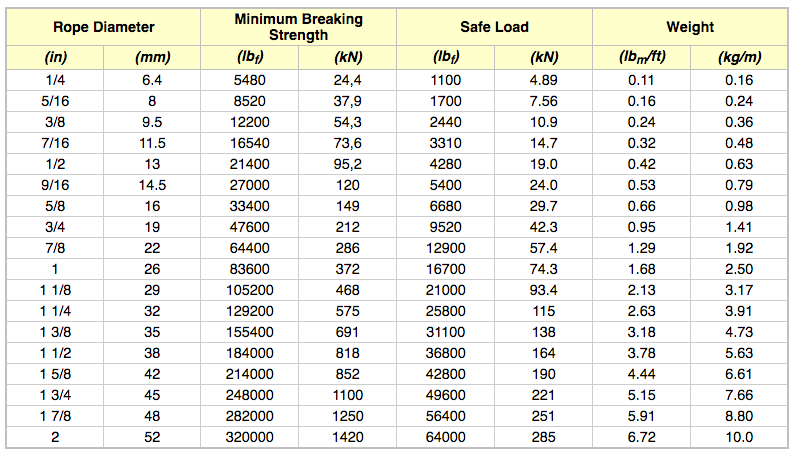
Safe Working Load (SWL) sometimes stated as the Normal Working Load (NWL) is the mass or force that a piece of lifting equipment, lifting device or accessory can safely utilize to lift, suspend, or lower a mass without fear of breaking. Usually marked on the equipment by the manufacturer and is often 1/5 of the Minimum Breaking Strength (MBS) although other fractions may be used such as 1/4, 1/6 and 1/10.[1][2][3]
Other synonyms include Working Load Limit (WLL), which is the maximum working load designed by the manufacturer. This load represents a force that is much less than that required to make the lifting equipment fail or yield, also known as the Minimum Breaking Load (MBL). SWL or WLL are calculated by dividing MBL by a safety factor (SF). An example of this would be a chain that has a MBL of 2000 lbf (8.89 kN) would have a SWL or WLL of 400 lbf (1.78 kN) if a safety factor of 5 (5:1, 5 to 1, or 1/5) is used.
Here at Industrial Rope Supply, we are not only committed to providing you with a quality product, but also with all the information needed to insure safety comes first on every job. Have safety questions on a product purchased from us? Contact us today and we’ll be happy to talk you through and/or provide you with the safety materials needed.
Wire ropes are essential for safety purposes on construction sites and industrial workplaces. They are used to secure and transport extremely heavy pieces of equipment – so they must be strong enough to withstand substantial loads. This is why the wire rope safety factor is crucial.
You may have heard that it is always recommended to use wire ropes or slings with a higher breaking strength than the actual load. For instance, say that you need to move 50,000 lbs. with an overhead crane. You should generally use equipment with a working load limit that is rated for weight at least five times higher – or 250,000 lbs. in this case.
This recommendation is all thanks to the wire rope safety factor. This calculation is designed to help you determine important numbers, such as the minimum breaking strength and the working load limit of a wire rope.
The safety factor is a measurement of how strong of a force a wire rope can withstand before it breaks. It is commonly stated as a ratio, such as 5:1. This means that the wire rope can hold five times their Safe Work Load (SWL) before it will break.
So, if a 5:1 wire rope’s SWL is 10,000 lbs., the safety factor is 50,000 lbs. However, you would never want to place a load near 50,000 lbs. for wire rope safety reasons.
The safety factor rating of a wire rope is the calculation of the Minimum Break Strength (MBS) or the Minimum Breaking Load (MBL) compared to the highest absolute maximum load limit. It is crucial to use a wire rope with a high ratio to account for factors that could influence the weight of the load.
The Safe Working Load (SWL) is a measurement that is required by law to be clearly marked on all lifting devices – including hoists, lifting machines, and tackles. However, this is not visibly listed on wire ropes, so it is important to understand what this term means and how to calculate it.
The safe working load will change depending on the diameter of the wire rope and its weight per foot. Of course, the smaller the wire rope is, the lower its SWL will be. The SWL also changes depending on the safety factor ratio.
The margin of safety for wire ropes accounts for any unexpected extra loads to ensure the utmost safety for everyone involved. Every year there aredue to overhead crane accidents. Many of these deaths occur when a heavy load is dropped because the weight load limit was not properly calculated and the wire rope broke or slipped.
The margin of safety is a hazard control calculation that essentially accounts for worst-case scenarios. For instance, what if a strong gust of wind were to blow while a crane was lifting a load? Or what if the brakes slipped and the load dropped several feet unexpectedly? This is certainly a wire rope safety factor that must be considered.
Themargin of safety(also referred to as the factor of safety) measures the ultimate load or stress divided by theallowablestress. This helps to account for the applied tensile forces and stress thatcouldbe applied to the rope, causing it to inch closer to the breaking strength limit.
A proof test must be conducted on a wire rope or any other piece of rigging equipment before it is used for the first time.that a sample of a wire rope must be tested to ensure that it can safely hold one-fifth of the breaking load limit. The proof test ensures that the wire rope is not defective and can withstand the minimum weight load limit.
First, the wire rope and other lifting accessories (such as hooks or slings) are set up as needed for the particular task. Then weight or force is slowly added until it reaches the maximum allowable working load limit.
Some wire rope distributors will conduct proof loading tests before you purchase them. Be sure to investigate the criteria of these tests before purchasing, as some testing factors may need to be changed depending on your requirements.
When purchasing wire ropes for overhead lifting or other heavy-duty applications, understanding the safety dynamics and limits is critical. These terms can get confusing, but all of thesefactors serve an important purpose.
Our company has served as a wire rope distributor and industrial hardware supplier for many years. We know all there is to know about safety factors. We will help you find the exact wire ropes that will meet your requirements, no matter what project you have in mind.
Examine slings for wear, fatigue, crushed or broken wires, kinking, ballooning or "bird-caging", heat damage, etc. Check both before and after using slings to detect any damage or defects. See Hoist wire rope for more inspection tips.
The PMI Wire Rope Sling are excellent temporary and semi-permanent ANSI certified anchors. The Iridescent blue tubing makes for easier cable inspections. The breaking strength of 5000 pounds allows for versatility on the job or in a rescue kit. The rope sling is ANSI Z359 certified. OSHA 1926.251(a)(2)(i) states that material handling equipment "Has permanently affixed and legible identification markings as prescribed by the manufacturer that indicates the recommended safe working load" For our material handling slings, please see our Lifting and Rigging Slings.
Our wire rope slings comply with the Supply of Machinery (Safety) Regulations. Wire rope fittings and steel rope are matched up against each other to suit the required load. They go through thorough quality assurances and are clearly labelled to maximise safety. Slinging arrangements are made up to order, in accordance with your specifications.
Various end fittings and end fitting combinations are available for online quotation, where you can choose the complete configuration of the sling that you require. If you require any additional features such as fibre core, or the construction of the wire e.g. 6x36 IWRC, please add this into the additional information box at the end of constructing your wire ropes.
The working load limits of slings made from general engineering ropes to BS EN 12385-4 should conform to BS EN 13414-1: 2003. Note that the working load limits shown are based on the assumption that soft-eyes of single-part slings are used over bearing points of not less than twice the normal diameter of the rope. All sling ropes must be ordinary lay.
The Safe Working Load will normally be equal to the Working Load Limit but in some circumstances it may be less e.g. If the sling is used in choke hitch SWL=WLL x 0.8.
BS EN 13414-1 covers only those sling assemblies that have legs of equal nominal length, diameter, construction and tensile grade. While sling assemblies with legs of unequal length may be made up generally in accordance with the requirements of BS EN 13414-1, it must be stressed that their rating requires special consideration by a competent person.
In all cases, where hooks or shackles are used, the WLL of the hooks and shackles shall never be less than the WLL of the leg which they are fitted to.
When using multi-leg sling assemblies, remember that increasing the angles between the legs will increase the load in each leg. Examine all slings before use, and discard any that are defective. Slings which are found to be unfit for use should be destroyed by cutting them up - not put on a refuse dump. ‘Hooking back’ to the leg of a sling is not recommended. The Safe Working Load of slings is affected by the method of usage. Check that the crane hook is positioned over the loads centre of gravity to prevent swinging when the load is being raised. Correct signals, according to the recognised code, should be given to the crane driver. The signals must be given by the person responsible for the lift and nobody else.
Keep the wire rope sling away from welding and flame cutting operations. The Law requires that all lifting tackle must be examined by a competent person at regular intervals. Users should not store away slings and regard them as their own private slinging assemblies, as this could lead to them being overlooked at inspection time.

A lifting sling has a purpose, which is to move bulky, large, and heavy loads. Slings are used because lifting without them can be difficult and sometimes not even possible. Lifting slings makes a direct connection between the load and the lifting equipment being used. Although these slings are used to make lifting more accessible, they can make lifting more dangerous if the straps are misused. Anytime a sling is used for lifting, it is essential that users take concrete steps and precautions.
A lifting sling should be inspected before every use (including the first time). A damaged sling can break while lifting loads. Dropping loads can harm people, products, and the environment.
Different sling styles and sizes exist, and so not all can be used interchangeably. When it comes to lifting tools, you need the right sling for the job. Webbing slings have a full surface, which can help to protect larger loads.
Never exceed the working limit for a load. All lifting devices, like cranes and hoists, are rated for the weight they can carry. Lifting slings are calculated similarly. If you are lifting an object that is roughly 18 tonnes, you will want to acquire slings that have a WLL (working load limit) of 20 tonnes.

The Working Load Limit is the maximum load which should ever be applied to the product, even when the product is new and when the load is uniformly applied – straight line pull only. Avoid side loading. All catalog ratings are based upon usual environmental conditions and consideration must be given to unusual conditions such as extreme high or low temperatures, chemical solutions or vapors, prolonged immersion in salt water, etc. Never exceed the Working Load Limit.
The term “Proof Test” designates a quality control test applied to the product for the sole purpose of detecting defects in material or manufacture. The Proof Test Load (usually twice the Working Load Limit) is the load which the product withstood without deformation when new and under laboratory test conditions. A constantly increasing force is applied in direct line to the product at a uniform rate of speed on a standard pull testing machine. The Proof Test Load does not mean the Working Load Limit should ever be exceeded.
Do not use breaking strength as a criterion for service or design purposes. Refer to the Working Load Limit instead. Breaking Strength is the average force at which the product, in the condition it would leave the factory, has been found by representative testing to break, when a constantly increasing force is applied in direct line to the product at a uniform rate of speed on a standard pull testing machine. Proof testing to twice the Working Load Limit does not apply to hand-spliced slings. Remember: Breaking Strengths, when published, were obtained under controlled laboratory conditions. Listing of the Breaking Strength does not mean the Working Load Limit should ever be exceeded.
An industry term usually computed by dividing the catalog Breaking Strength by the catalog Working Load Limit and generally expressed as a ratio. For example: 5 to 1.
A load resulting from rapid change of movement, such as impacting, jerking or swinging of a static load. Sudden release of tension is another form of shock loading. Shock loads are generally significantly greater than static loads. Any shock loading must be considered when selecting the item for use in a system.
Safe rigging practices are essential to get the job done and get home in one piece. Today, we spoke to our rigging experts from our Brampton, Ontario branch—some of their clients include IMAX, Siemens, GM and Bombardier. Read on to learn more about safe rigging practices to use when rigging with wire rope slings.
Rigging, or safe rigging is simply the movement of a mass using mechanical application, like slings and/or lifting equipment. The term ‘rigging’ also includes figuring out what lifting appliances and slings should be used and fitted to control the load (never vice versa!), and where the load should be moved to.
Okay, so you’ve decided wire rope slings are the best sling to lift your load—but wait! Before lifting with wire rope slings, determine these 3 things:
When executing your lift with a wire rope sling, be sure to protect the load and sling from damage at sharp corners—padding the corners is recommended. Be sure to block as needed, examine your sling before each lift and use safe operating practices. This will also help prevent common wire rope sling damage.
If the load needs a multi-leg sling, do not exceed the SWL stamped on the ring—the SWL (safe working load) will always be slated for sling legs at 90°.
Tubular items include scaffold tubes, drilling tubulars, construction pipe work and other items like these. When rigging tubulars in a sling, consider the following:
Use clamps or bulldog clips on the reeved wire to prevent loosening. Use a tie wrap on the sling’s reeved eye to prevent the sling from slipping over the bulldog;
Remember—it’s dangerous to bundle tube with steel angle, channels, etc. Small bore tube may lay loose in the gaps between differently shaped items of steel and could slide out when lifted. At height with the right amount of force, a tube can become a spear and result in fatal injuries.
Hercules SLR spreader beam.Use a certified spreader beam for good control to support loads that are long and/or hard-to-handle. They reduce the tendency for the load to slip or bend, and both single legs will support the load—if the load is evenly balanced, each side will carry half the load.
slippage. These are great for handling loose materials as it has a 360° wrap that can be achieved without battening down the eye—gain control by using two hitches at a horizontal angle of 45° or smaller.
Before you begin lifting your load, you should have a plan and prepared space for the load to land. The type of load will determine how riggers prepare but typically, most loads should be lowered onto timber battens. Slings will be easy to withdraw from the load, but remember—never land a load directly on the sling.
A good rigger will always asses unusual loads and try to estimate their centre of gravity in order to stabilize it. It’s important to attach slings so the centre of gravity is below or within the lift points. If you doubt the load’s stability at all, lift it very slowly. If it tilts, lower it (slowly) and re-sling the load so it’s stable.
Hercules SLR is part of the Hercules Group of Companies which offers a unique portfolio of businesses nationally with locations from coast to coast. Our companies provide an extensive coverage of products and services that support the success of a wide range of business sectors across Canada including the energy, oil & gas, manufacturing, construction, aerospace, infrastructure, utilities, oil and gas, mining and marine industries.


 8613371530291