
safety factor for wire rope slings made in china
We are one of the best webbing sling suppliers in China. Flat duplex webbing sling is made from high tensile polyester yarn or nylon, then weaving the match the polyester yarn by looming machines bought from Kyang Hye, and Swiss Jakob Müller AG, dyeing machine helps to perform two operations on flat woven webbing sling, heating and cooling processes experienced by the webbing help to colour coded according to Safe Working Load Limit, Sewing step is the last and greatest important, we can produce simplex (single ply), duplex webbing sling (double ply) also can up to 4 plies. Final, sewing the labels for synthetic web sling safety bulletin and re-Enforced becket eyes.
Raw Material High Tensile Tenacity Polyester Incoming → Yarn Matching → Raw Material Warping → Weaving → Dyeing → Measuring and Fusing → Joint Sewing and Burr Fusing (End Fitting Applying) → Multi strand wire rope → Sewing (synthetic web sling safety bulletin) → Test Inspection → Film Packing → Warehouse → Shipping
Synthetic web slings are sewn into different configurations and standards, such as eye and eye webbing sling ASME, webbing lifting slings EN1492-1 against different standard. polyester webbing sling, nylon web slings and dyneema webbing slings according to different webbing material. eye and eye webbing sling and endless webbing sling are different reinforced ending.
Duplex eye eye webbing sling has a closed loop eye connector on each end can be sewn into single, double or multi plies with eye and eye type or endless grommet shape, the most common synthetic web slings are eye eye webbing sling (duplex plies) with high tenacity load rating can easily lift heavy duty equipment.
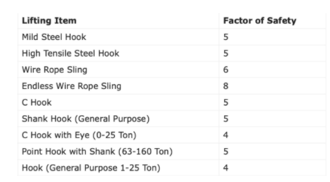
The webbing sling safety factor 8:1 is widely used for overhead lifting, delicate loads, for they feature more stronger, durable and relatively flexible, light weight than steel wire rope slings and chain slings. Perhaps the only significant concern of using synthetic web slings is they are more susceptible to potential damage such as cutting, tearing, abrasion, heat and U.V. degradation than wire rope slings or chain slings. So it is very important to inspect webbing sling regularly, here are some rules you need to know:
Synthetic web slings both end can pair with rigging accessories to conjunct with a crane or some type of lifting device, such as hooks, rings or other attachments.
We offer the length of US Standard Flat Webbing Slings Eye & Eye from 1m to 12m usually but also can OEM or ODM against customers’ requests and M.B.S (lbs) from 15500 lbs to 14200 lbs.

Wire rope is often used in slings because of its strength, durability, abrasion resistance and ability to conform to the shape of the loads on which it is used. In addition, wire rope slings are able to lift hot materials.
Wire rope used in slings can be made of ropes with either Independent Wire Rope Core (IWRC) or a fiber-core. It should be noted that a sling manufactured with a fiber-core is usually more flexible but is less resistant to environmental damage. Conversely, a core that is made of a wire rope strand tends to have greater strength and is more resistant to heat damage.
Wire rope may be manufactured using different rope lays. The lay of a wire rope describes the direction the wires and strands are twisted during the construction of the rope. Most wire rope is right lay, regular lay. This type of rope has the widest range of applications. Wire rope slings may be made of other wire rope lays at the recommendation of the sling manufacturer or a qualified person.
Wire rope slings are made from various grades of wire rope, but the most common grades in use are Extra Improved Plow Steel (EIPS) and Extra Extra Improved Plow Steel (EEIPS). These wire ropes are manufactured and tested in accordance with ASTM guidelines. If other grades of wire rope are used, use them in accordance with the manufacturer"s recommendations and guidance.
When selecting a wire rope sling to give the best service, consider four characteristics: strength, ability to bend without distortion, ability to withstand abrasive wear, and ability to withstand abuse.
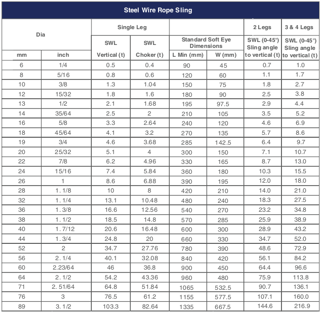
Rated loads (capacities) for single-leg vertical, choker, basket hitches, and two-, three-, and four-leg bridle slings for specific grades of wire rope slings are as shown in Tables 7 through 15.
Rated loads for a sling in a choker hitch are the values shown in Table 7, 9, 11, 13, 14, or 15, provided that the angle of the choke is 120 degrees or more (Fig. 2). Use the values in Fig. 2 or those from the sling manufacturer or a qualified person for angles of choke less than 120 degrees.
Ensure that slings made of rope with 6×19 and 6x37 classifications and cable slings have a minimum clear length of rope 10 times the component rope diameter between splices, sleeves, or end fittings unless approved by a qualified person,
Ensure that braided slings have a minimum clear length of rope 40 times the component rope diameter between the loops or end fittings unless approved by a qualified person,
Ensure that grommets and endless slings have a minimum circumferential length of 96 times the body diameter of the grommet or endless sling unless approved by a qualified person, and
Perform welding of handles or other accessories to end attachments, except covers to thimbles, before assembly of the sling. Ensure that welded end attachments are proof tested by the manufacturer or a qualified person. Retain the certificates of proof test and make them available for examination.
Do not use wire rope clips to fabricate wire rope slings, except where the application precludes the use of prefabricated slings and where the sling is designed for the specific application by a qualified person,
Use damaged slings only after they are repaired, reconditioned, and proof tested by the sling manufacturer or a qualified person using the following criteria:
Ensure that wire rope slings have suitable characteristics for the type of load, hitch, and environment in which they will be used and that they are not used with loads in excess of the rated load capacities described in the appropriate tables. When D/d ratios (Fig. 4) are smaller than those listed in the tables, consult the sling manufacturer. Follow other safe operating practices, including:
Ensure that multiple-leg slings are selected according to Tables 7 through 15 when used at the specific angles given in the tables. Ensure that operations at other angles are limited to the rated load of the next lower angle given in the tables or calculated by a qualified person,
When D/d ratios (see Fig. 6) smaller than those cited in the tables are necessary, ensure that the rated load of the sling is decreased. Consult the sling manufacturer for specific data or refer to the WRTB (Wire Rope Technical Board) Wire Rope Sling Users Manual, and
Ensure that the load applied to the hook is centered in the base (bowl) of the hook to prevent point loading on the hook, unless the hook is designed for point loading,
Before initial use, ensure that all new swaged-socket, poured-socket, turnback-eye, mechanical joint grommets, and endless wire rope slings are proof tested by the sling manufacturer or a qualified person.
Permanently remove from service fiber-core wire rope slings of any grade if they are exposed to temperatures in excess of 180 degrees F (82 degrees C).
Follow the recommendations of the sling manufacturer when you use metallic-core wire rope slings of any grade at temperatures above 400 degrees F (204 degrees C) or below minus 40 degrees F (minus 40 degrees C).
Original equipment wire rope and replacement wire rope must be selected and installed in accordance with the requirements of this section. Selection of replacement wire rope must be in accordance with the recommendations of the wire rope manufacturer, the equipment manufacturer, or a qualified person.
Wire rope design criteria: Wire rope (other than rotation resistant rope) must comply with either Option (1) or Option (2) of this section, as follows:
Option (1). Wire rope must comply with section 5-1.7.1 of ASME B30.5-2004 (incorporated by reference, see § 1926.6) except that section"s paragraph (c) must not apply.
Option (2). Wire rope must be designed to have, in relation to the equipment"s rated capacity, a sufficient minimum breaking force and design factor so that compliance with the applicable inspection provisions in § 1926.1413 will be an effective means of preventing sudden rope failure.
Type I rotation resistant wire rope ("Type I"). Type I rotation resistant rope is stranded rope constructed to have little or no tendency to rotate or, if guided, transmits little or no torque. It has at least 15 outer strands and comprises an assembly of at least three layers of strands laid helically over a center in two operations. The direction of lay of the outer strands is opposite to that of the underlying layer.
Type II rotation resistant wire rope ("Type II"). Type II rotation resistant rope is stranded rope constructed to have significant resistance to rotation. It has at least 10 outer strands and comprises an assembly of two or more layers of strands laid helically over a center in two or three operations. The direction of lay of the outer strands is opposite to that of the underlying layer.
Type III rotation resistant wire rope ("Type III"). Type III rotation resistant rope is stranded rope constructed to have limited resistance to rotation. It has no more than nine outer strands, and comprises an assembly of two layers of strands laid helically over a center in two operations. The direction of lay of the outer strands is opposite to that of the underlying layer.
Type I must have an operating design factor of no less than 5, except where the wire rope manufacturer and the equipment manufacturer approves the design factor, in writing.
When Types II and III with an operating design factor of less than 5 are used (for non-duty cycle, non-repetitive lifts), the following requirements must be met for each lifting operation:
A qualified person must inspect the rope in accordance with § 1926.1413(a). The rope must be used only if the qualified person determines that there are no deficiencies constituting a hazard. In making this determination, more than one broken wire in any one rope lay must be considered a hazard.
Each lift made under § 1926.1414(e)(3) must be recorded in the monthly and annual inspection documents. Such prior uses must be considered by the qualified person in determining whether to use the rope again.
Rotation resistant ropes may be used as boom hoist reeving when load hoists are used as boom hoists for attachments such as luffing attachments or boom and mast attachment systems. Under these conditions, all of the following requirements must be met:
The requirements in ASME B30.5-2004 sections 5-1.3.2(a), (a)(2) through (a)(4), (b) and (d) (incorporated by reference, see § 1926.6) except that the minimum pitch diameter for sheaves used in multiple rope reeving is 18 times the nominal diameter of the rope used (instead of the value of 16 specified in section 5-1.3.2(d)).
The operating design factor for these ropes must be the total minimum breaking force of all parts of rope in the system divided by the load imposed on the rope system when supporting the static weights of the structure and the load within the equipment"s rated capacity.
Wire rope clips used in conjunction with wedge sockets must be attached to the unloaded dead end of the rope only, except that the use of devices specifically designed for dead-ending rope in a wedge socket is permitted.
Prior to cutting a wire rope, seizings must be placed on each side of the point to be cut. The length and number of seizings must be in accordance with the wire rope manufacturer"s instructions.

This website is using a security service to protect itself from online attacks. The action you just performed triggered the security solution. There are several actions that could trigger this block including submitting a certain word or phrase, a SQL command or malformed data.
This website is using a security service to protect itself from online attacks. The action you just performed triggered the security solution. There are several actions that could trigger this block including submitting a certain word or phrase, a SQL command or malformed data.
Hilifting is the best round sling supplier in China, not only can manufacture round sling according to ASME standard for Australia market, but also AS4497 & EN1492-2 for US and EU market.

Wire rope slings adopt precast concrete construction and the main parts include wire rope, inner core, strand, center, steel wire, steel stocks and others.
We can customize various kinds of rigging according to customers’ requirement. Usually, the minimum circumference S of the sling is 50 times the wire rope diameter and the bending radius must be not less than 4 times of the wire rope diameter. The zone between the clamps can’t be bent under lifting force and the length is intended to be the dimension measured between the bearing points of the slings and the measured length of a ferrule-secured sling shall not differ from the nominal length by more than two rope diameters or 1% of the nominal length.
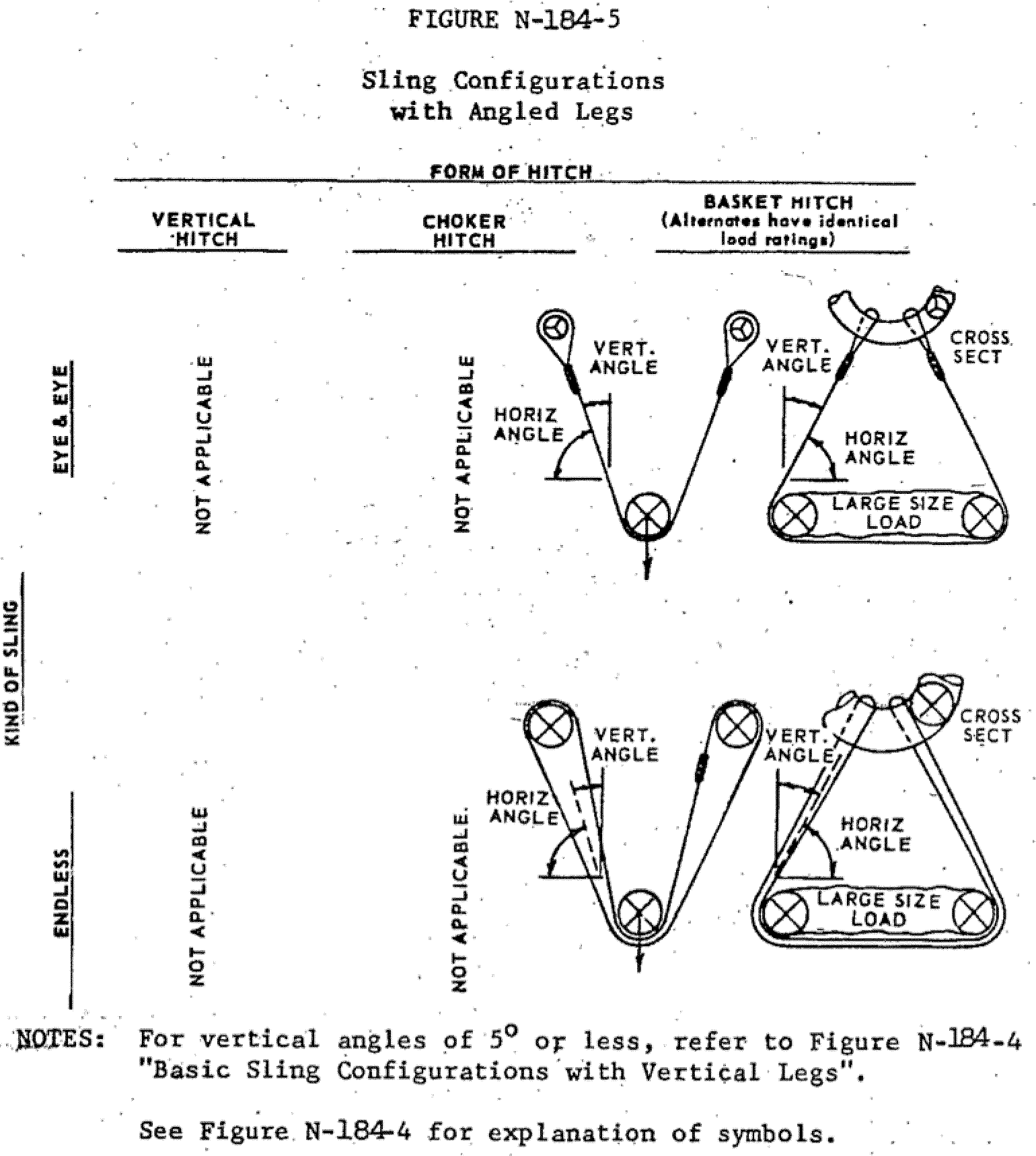
①Vertical hitches are made directly from the crane hook to the load. Full rated capacity of the slings may be used but never exceeded. A tagline should be attached to prevent rotation which can damage the sling. A sling with a hand-tucked splice can’t lay and fail if the sling is allowed to rotate.
②Choker hitches reduce lifting capability of a sling, since this method of rigging affects the ability of the wire rope components to adjust during the lift, places angular loading on the body of the sling, and creates a small diameter bend in the body at the choke point.
Wire rope slings are always packaged in plywood reel/plastic reel/wooden reel/coil in container, and then they will be palletized or put into a crate or a box.
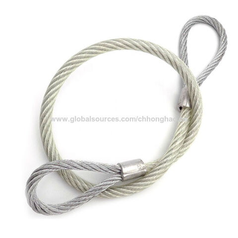
There are various types of wire rope slings including slings with soft eye, hoist slings, slings with soft eye and two legs, steel ferrule secured slings, slings with Flemish eyes, ferrule secured endless slings, slings with steel-ferrule secured end stops, slings with swaged steel tie rod, slings with single hook, slings for crane, slings with sockets, slings with master link and two legs, slings with cuneiform connector, flat wire rope mesh slings, slings with master link and four legs, endless wire rope slings, container lifting slings for sea oil platform, large diameter cable laid slings, slings for lifting reinforcing steel bars, cable laid grommet slings, cable stocking, slings with spliced eye termination and others, and the main products are as following.
2-Leg bridle slings constructed of two wire rope assemblies that are attached to an oblong ring are designed for general lifting when the attachment can be made directly to the load. The lifting ends of the wire rope legs can be fitted with a variety of hooks, eyes, or rings to allow attachment to nearly any object. The advantage of wire rope slings is that they are resistant to corrosion, heat, sunlight and most chemicals and they are custom built to meet your specific needs for any application.
3-Leg bridle wire rope slings constructed of three wire rope assemblies that are attached to an oblong ring are designed to handle unbalanced loads. The lifting ends of the wire rope legs can be fitted with a variety of hooks, eyes, or rings to allow attachment to nearly any object. We carry a range of wire rope slings in our hire fleet with soft eye configurations at each end, available in various capacities and effective working lengths.
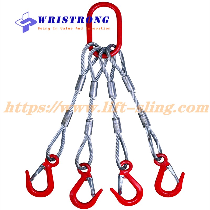
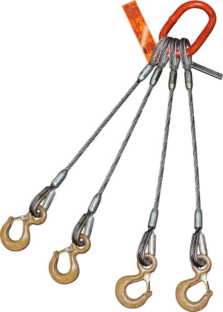
4-Leg bridle wire rope lifting slings constructed of four wire rope assemblies that are attached to an oblong ring are designed for balanced or unbalanced loads and for heavy lifts when the weight can easily be distributed over four points. The lifting ends of the wire rope legs can be fitted with a variety of hooks, eyes, or rings to allow attachment to nearly any object.
The endless wire rope slings are orbicular, economical and adaptable slings with no fixed wear points, using special technology and the most advanced equipment and known for its softness, high tension and increased suspension points. They are suitable to lift and move tubes, pipes and long metal parts which suited in small and limited spaces and for high/large lifting loads, they are also adaptable for special bulk hoisting requirements of different conditions, such as transformers, shipbuilding and special machinery (where the warning mark locates cannot be used as lifting point)
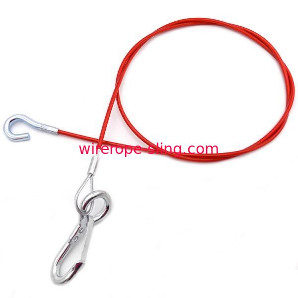
Slings can be realized with galvanized or ungalvanized wire rope, special rope protected by strong PVC sleeve to resist against sharp edges without damaging the goods surface is also available as per your request.
7. According to the strength, wire rope slings can be divided into vertical breaking strength, chocker breaking strength, basket breaking strength, and except for standard eye size, thimble eye size, there are others of different eye hook capacity.
④Evidence of heat damage or if a wire rope sling having a fiber core is exposed to temperatures in excess of 200° F or if a wire rope sling having a steel core is used at temperatures above 400° F or below minus 60° F.
⑤Corrosion of the rope or end attachments or not laying and opening up of a tucked splice. Also, when end attachments that are cracked, deformed, or worn.
⑥Deformation—any visibly apparent bend or twist from the plane of the unbent hook. Throat opening—any distortion will cause an increase in throat opening of 5% not to exceed capacity.
⑦Avoid twists, kinks and knots before lifting, store wire rope slings where they will not be subjected to dirt, moisture, extreme heat, corrosion or mechanical damage.
⑧Protect the sling body against sharp edges and corners of loads, protrusions or abrasive surfaces. Sharp bends can distort wire rope and reduce its strength.
⑨Never "shock load" wire rope slings, the actual force caused by a sudden application of load can easily exceed rated capacities and damage slings and abruptly releasing a load can also damage the slings.

Wire ropes are essential for safety purposes on construction sites and industrial workplaces. They are used to secure and transport extremely heavy pieces of equipment – so they must be strong enough to withstand substantial loads. This is why the wire rope safety factor is crucial.
You may have heard that it is always recommended to use wire ropes or slings with a higher breaking strength than the actual load. For instance, say that you need to move 50,000 lbs. with an overhead crane. You should generally use equipment with a working load limit that is rated for weight at least five times higher – or 250,000 lbs. in this case.
This recommendation is all thanks to the wire rope safety factor. This calculation is designed to help you determine important numbers, such as the minimum breaking strength and the working load limit of a wire rope.
The safety factor is a measurement of how strong of a force a wire rope can withstand before it breaks. It is commonly stated as a ratio, such as 5:1. This means that the wire rope can hold five times their Safe Work Load (SWL) before it will break.
So, if a 5:1 wire rope’s SWL is 10,000 lbs., the safety factor is 50,000 lbs. However, you would never want to place a load near 50,000 lbs. for wire rope safety reasons.
The safety factor rating of a wire rope is the calculation of the Minimum Break Strength (MBS) or the Minimum Breaking Load (MBL) compared to the highest absolute maximum load limit. It is crucial to use a wire rope with a high ratio to account for factors that could influence the weight of the load.
The Safe Working Load (SWL) is a measurement that is required by law to be clearly marked on all lifting devices – including hoists, lifting machines, and tackles. However, this is not visibly listed on wire ropes, so it is important to understand what this term means and how to calculate it.
The safe working load will change depending on the diameter of the wire rope and its weight per foot. Of course, the smaller the wire rope is, the lower its SWL will be. The SWL also changes depending on the safety factor ratio.
The margin of safety for wire ropes accounts for any unexpected extra loads to ensure the utmost safety for everyone involved. Every year there aredue to overhead crane accidents. Many of these deaths occur when a heavy load is dropped because the weight load limit was not properly calculated and the wire rope broke or slipped.
The margin of safety is a hazard control calculation that essentially accounts for worst-case scenarios. For instance, what if a strong gust of wind were to blow while a crane was lifting a load? Or what if the brakes slipped and the load dropped several feet unexpectedly? This is certainly a wire rope safety factor that must be considered.
Themargin of safety(also referred to as the factor of safety) measures the ultimate load or stress divided by theallowablestress. This helps to account for the applied tensile forces and stress thatcouldbe applied to the rope, causing it to inch closer to the breaking strength limit.
A proof test must be conducted on a wire rope or any other piece of rigging equipment before it is used for the first time.that a sample of a wire rope must be tested to ensure that it can safely hold one-fifth of the breaking load limit. The proof test ensures that the wire rope is not defective and can withstand the minimum weight load limit.
First, the wire rope and other lifting accessories (such as hooks or slings) are set up as needed for the particular task. Then weight or force is slowly added until it reaches the maximum allowable working load limit.
Some wire rope distributors will conduct proof loading tests before you purchase them. Be sure to investigate the criteria of these tests before purchasing, as some testing factors may need to be changed depending on your requirements.
When purchasing wire ropes for overhead lifting or other heavy-duty applications, understanding the safety dynamics and limits is critical. These terms can get confusing, but all of thesefactors serve an important purpose.
Our company has served as a wire rope distributor and industrial hardware supplier for many years. We know all there is to know about safety factors. We will help you find the exact wire ropes that will meet your requirements, no matter what project you have in mind.
The LKING STEEL LIMITED 6 x 37 IWRC (independent wire rope core) single-leg wire rope sling has eye-and-eye endings and a mechanical splice for lifting loads with vertical, choker, or basket configurations in general industry applications. The 6 x 37 IWRC construction contains six strands of wire rope with approximately 37 wires per strand wrapped around a separate 7 X 7 wire rope, which has seven strands with seven wires per strand, in the center of the sling. This construction provides more flexibility than a 6 x 7 or 6 x 19 wire rope sling. The wire rope construction has more abrasion and heat resistance than a web sling. This eye-and-eye sling has an eye, or loop, on both ends, and can be used with vertical, choker, and basket lifting configurations. The eyes are secured with a mechanical (also called Flemish) splice that is stronger than a hand splice. This sling has a minimum D/d ratio of 25 and meets American Society of Mechanical Engineers (ASME) specification B30.9 and Occupational Safety and Health Administration (OSHA) specification 1910.184.
Slings are used to lift heavy objects for industrial applications. Types of slings include web slings, wire rope slings, chain slings, and mesh slings. The appropriate type of sling for an application depends on the strength-to-weight ratio, flexibility and resistance to bending, resistance to abrasion and cutting, resistance to crushing, resistance to stretching, and resistance to high temperatures and other environmental stressors. Slings have one, two, three, or four legs; or a continuous loop of webbing or wire rope. Legs are support branches that extend from a single point at the top of the sling to the item being lifted so the weight of the load is distributed evenly among the branches. Slings have eyes (loops) or alloy steel fittings on the ends.
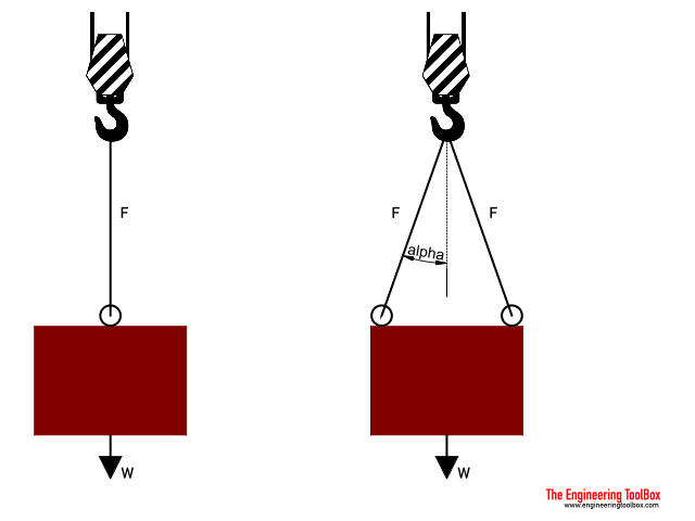
A vertical lifting configuration connects a crane hook directly to a load with a single, vertical sling, usually by means of a hook. In a choker configuration, the sling wraps entirely around the load, and one loop passes through the other to form a slip noose, or choker. In a basket configuration, the sling passes under the load and both ends of the sling connect to the crane hook. Load capacity is the maximum weight to be lifted in a vertical configuration. The capacity in a choker configuration is approximately equal to the vertical capacity times 0.8. The capacity in a basket configuration, with sling ends at a 90-degree angle, is approximately equal to twice the vertical capacity. Load capacity in a basket configuration decreases if the angle of the sling is less than 90 degrees. For example, a sling with a capacity of 2,000 lb. in a vertical configuration will have an approximate capacity of (2,000)(0.8)=1,600 lb. in a choker configuration and an approximate capacity of (2,000)(2)=4,000 lb. in a basket configuration, if the sling ends are at a 90-degree angle to the load. A wire rope sling"s capacity in a basket configuration applies only when the configuration meets the sling"s minimum D/d ratio, which is the ratio of the diameter of the rope"s curve around the load (D) to the diameter of the sling (d). If the minimum D/d ratio is not met, the capacity of the sling is decreased.
LKING STEEL LIMITED Lifting Technologies manufactures lifting solutions including slings, cranes, and hoists. Founded in 1967, the company is headquartered in Shanghai, China.
B) if the 2legswire rope sling, the hanging points should be on both sides of the goods and the hooks are above the center of gravity of the suspended objects.
C) if it is three legs or four legs wire rope sling, the hanger must be proportioned on the plane around the cargo and the hook is located directly above the center of gravity of the suspended object.
(a) Wire rope slings must be made from new or unused regular lay wire rope. The wire rope must be manufactured and tested in accordance with ASTM A 1023-02 and ASTM A 586.
(f) Wire rope clips, if used, must be installed and maintained in accordance with the recommendations of the clip manufacturer or a qualified person, or in accordance with the provisions of ASME B30.26-2010.
(g) You must not use slings made with wire rope clips as a choker hitch.Note:If using wire rope clips under these conditions, follow the guidance given in Table 5.
Number, Torque Values, and Turn Back Requirements for U-Bolt Wire Rope ClipsNumber, Torque Values, and Turn Back Requirements for Double Saddle (Fist Grip) Wire Rope Clips
•Slings made of rope with 6x19 and 6x36 classification.A minimum clear length of rope 10 times the rope diameter between splices, sleeves, or end fittings (see Figure 4, Minimum Sling Length) unless approved by a qualified person.
•Braided slings.A minimum clear length of rope 40 times the component rope diameter between the loops or end fittings (see Figure 5, Minimum Braided Sling Length) unless approved by a qualified person.
•Grommets and endless slings.A minimum circumferential length of 96 times the body diameter of the grommet or endless sling unless approved by a qualified person.
(b) You must rate slings with the load capacity of the lowest rated component of the sling. For example, if you use fittings that are rated lower than the sling material itself, identify the sling with the lower rated capacity.
(3) Identification information. All wire rope slings must have legible identification information attached to the sling which includes the information below, see sample tag in Figure 6. For slings in use that are manufactured before the effective date of this rule, the information below must be added before use or at the time the periodic inspection is completed.
Sample Wire Rope Sling ID TagNote:Sample tag for a 1/2" single-leg sling 6x19 or 6x36 classification, extra improved plow steel (EIPS) grade fiber core (FC) wire rope with a mechanical splice (ton = 2,000 lb).
(b) You must consider modification or alterations to end attachments or fittings must be considered as repairs and must conform to all other provisions of this part.
(6) Proof load tests. You must make sure the sling manufacturer or a qualified person proof load tests the following slings before initial use, according to Table 8:
(c) For single- or multiple-leg slings and endless slings, each leg must be proof loaded according to the requirements listed in Table 8 based on fabrication method. The proof load test must not exceed 50% of the component ropes" or structural strands" minimum breaking strength;
•Swaged socket and poured socket slings.Each leg to at least two times, but not more than two and 1/2 times, the single-leg vertical hitch rated load.
Note: For mechanical splice, swaged socket and poured socket slings follow the rope manufacturer"s recommendations for proof load testing provided that it is within the above-specified proof load range, including (c) of this subsection.
(a) You must use wire rope slings within the rated loads shown in Tables 7 through 15 in ASME B30.9-2010. For angles that are not shown in these tables, either use the rated load for the next lower angle or have a qualified person calculate the rated load.
(c) Rated loads for slings used in a choker hitch must conform to the values shown in the above referenced tables, provided that the angle of choke is 120 degrees or greater. See Figure 9 and Table 10, Angle of Choke.
(e) You must decrease the rated load of the sling when D/d ratios (Figure 8) smaller than 25 to one. Consult the sling manufacturer for specific data or refer to the Wire Rope Sling User"s Manual (wire rope technical board).
(g) Slings in contact with edges, corners, or protrusions must be protected with a material of sufficient strength, thickness, and construction to prevent damage to the sling. See Figure 3.
Grommet Wire Rope slings are made from one continuous strand of wire wire rope. The endless construction gives it the ability to be made in very short circumferences. Additionally, a Cable Grommet design gives extra capacity for the same size diameter rope in an equivalent eye to eye style sling.

A:Of course ,we have to know your application firstly and a number of factors have to be considered, such as work load, safety abrasion, environment ,cycle life, flexibility, , cost, When we design the steel wire cable assembly.
... All lifting keys act as attachment points for lifting solid precast concrete elements. As well as the million-times proven rope eyes, the user can also choose from flared lifting loops, special lifting loops and swivel ...
Manufactured according to SR EN 13414-1 they are available from non-galvanized, lubricated non-galvanized or galvanized wire ropes, in 6x19, 6x36 or 6x37 constructions for diameters between 1.5 and 78 mm.
... CarlStahl® offers this wire rope sling that can accommodate loads with capacity of 700 kg up to 25,000 kg. The attachment point for 1 leg wire rope slings ...
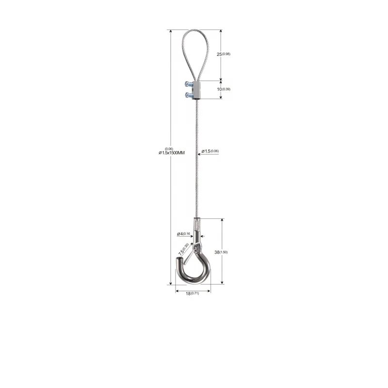
• Used to create safe anchoring point for working at height• PVC coated stainless steel wire rope of dia 8 mm. • The PVC coating prevents exposure to dirt and chemicals, hence increases ...
Steel wire rope and components are all manufactured according to strict specifications for quality and reliability, in-house or with proven top quality partners.
... configuration only, the Cable Sling is approved for use by one person at a time with approved systems. Two strands of cable sling must be of equal length to ensure an ...
With DirectIndustry you can: Find the product, subcontractor or service provider you need | Find a nearby distributor or reseller| Contact the manufacturer to get a quote or a price | Examine product characteristics and technical specifications for major brands | View PDF catalogues and other online documentation
Large Loads Require Large Slings Whatever the load you are lifting. YuanBo Wire Rope Factory can supply a steel wire rope sling to do the task. Sling up to 12" (305mm) diameter can be supplied with minimum braking loads up to tons. There arethree distinct types of Wire Rope Sling.
Slings manufactured from cable laid ropes, 4" diameter to 12" diameter. hand spliced or by combination of hand splicing and socketing with eye at each end.
Slings manufactured from 6 strand equal laid ropes. up to 3.5 " diameter with soft eyes spliced each end. terminated by either hand splicing or mechanical means.
The most common size: wire rope slings having soft eyes at both end used for heavy lifting operations with safety factor of 7, length 6m, 12m, 16m, 20m, and the swl from 5 ton to 40 ton.
A1: OEM or ODM are welcome! Samplings will be arranged after artwork/layout approved by you, Our designers will work on the most detailed requirements you can provide of it. &Off-the-shelf /in stock from factory, are available free of charge and ready to go anytime (NOTE**each customer is limited to get free one unit per style).
General, use a 5 to 1 or 3 to 1 safety factor when we design it. eg: breaking load is (1000 N)100 kgs, safety factor is 5:1 (200N), Breaking strength should never be considered the ropes working load.
A3: The same diameter of steel wire cable ,the 7X19 construction is more flexible than the 7X7 construction. eg:1/16’’7X19 steel wire rope more flexible than 1/16’’7X7
A4: Stainless steel cable has better corrosion resistance, but more expensive and slightly less tensile strength than galvanized wire cable. If it is used for general industry, galvanized steel is OK, as for marine environment, stainless steel wire cable will be recommended, It depends on you application.


 8613371530291