
sheave size for wire rope manufacturer
This website is using a security service to protect itself from online attacks. The action you just performed triggered the security solution. There are several actions that could trigger this block including submitting a certain word or phrase, a SQL command or malformed data.

Wire ropes are manufactured in a great variety of constructions to meet the varying demands of wire rope usage. Where abrasion is an important factor, the rope must be made of a coarse construction containing relatively large outer wires. In other cases, the great amount of bending to which the rope is subjected is more important. Here, a more flexible construction, containing many relatively small wires, is required. In either case, however, if the rope operates over inadequate size sheaves, the severe bending stresses imposed will cause the wires to break from fatigue, even though actual wear is slight. The smaller the diameter of the sheave, the sooner these fatigue breaks will occur and the shorter rope life becomes.
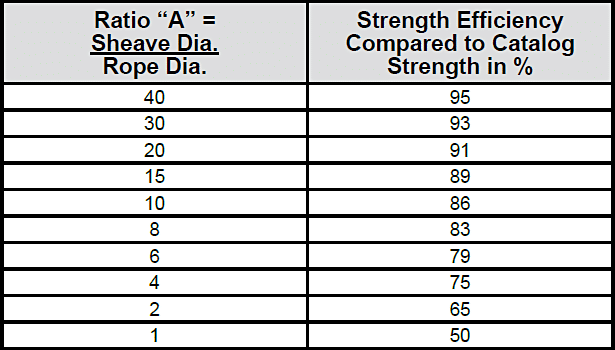
Another undesirable effect of small sheaves is accelerated wear of both rope and sheave groove. The pressure per unit area of rope on sheave groove for a given load is inversely proportional to the size of the sheave. In other words, the smaller the sheave the greater the rope pressure per unit area on the groove. Both sheaves and rope life can be prolonged by using the proper diameter sheave for the size and construction of rope. Sheave diameter also can influence rope strength. When a wire rope is bent around a sheave, there is a loss of effective strength due to the inability of the individual strands and wires to adjust themselves entirely to their changed position. Tests show that rope strength efficiency decreases to a marked degree as the sheave diameter is reduced with respect to the diameter of the rope.
A definite relationship exists between rope service and sheave size. As a guide to users, wire rope manufacturers have established standards for sheave sizes to be used with various rope constructions.
Generally, we recommend grooved drums only. The rope is spooled properly and positively. Depending on the drum/rope diameter relationship helix-grooved drums can be used for up to 3 layers without excessive rope wear. For applications with more than 3 layers (e.g. Mobile cranes) we recommend ‘Lebus’ grooving.
It has to be remembered, however, that rope service life on multiple layer drum systems will always only be a fraction of that compared with single layer helix-grooved drums.
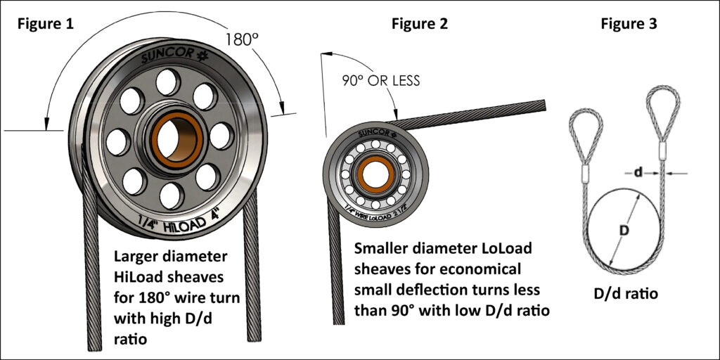
If these values are applied to single layer grooved drums the maximum permissible rope-deflection angle for regular wire rope constructions is 4°. For non rotating /rotation-resistant ropes the maximum permissible deflection angle is 1.5° only.
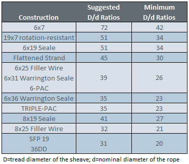
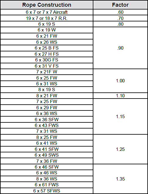
The service life of cable and wire rope can be increased if (1) it operates over the largest possible pulley or sheave diameter, and (2) it is properly supported in the pulley or sheave groove. The working life of the individual wire strands is greatly reduced as the pulley or sheave diameter is diminished. The chart below shows minimum tread diameters over which various sizes and constructions of cable should operate.
To find any tread diameter from this table, the diameter for the rope construction to be used is multiplied by its nominal diameter (d). For example, the minimum sheave tread diameter for a 1/2″ 6 x 21 FW rope would be 1/2″ (nominal diameter) x 30 (minimum ratio) or 15″.
NOTE:These values are for reasonable service. Other values are permitted by various standards such as ANSI, API, PCSA, HMI, CMAA, etc. Smaller values affect rope life.

Sheaves, drums and rollers must be of a correct design if optimum service is to be obtained from both the equipment and the wire rope. Because there are many different types of equipment and many different operating conditions, it is difficult to identify the one specific size of sheave or drum most appropriate for every application.
The guideline to follow is this: the most practical design is the one that most closely accommodates the limiting factors imposed by the equipment, the operating conditions and the wire rope.
All wire ropes operating over sheaves and drums are subjected to cyclic bending stresses, thus the rope wires will eventually fatigue. The magnitude of these stresses depends—all other factors being constant—upon the ratio of the diameter of the sheave or drum to the diameter of the rope.
Frequently, fatigue from cyclic, high-magnitude bending stress is a principal reason for shortened rope service. In order for a rope to bend around a sheave, the rope’s strands and wires must move relative to one another. This movement compensates for the difference in diameter between the underside and the top side of the rope, the distance being greater along the top side than it is on the underside next to the groove.
Proper rope movement (and service) is adversely affected if the wires cannot adjust to compensate for this length differential. Also, there can be additional limitations to wire movement because of excessive pressure caused by a sheave groove diameter which is too small, or by lack of rope lubrication. Avoid changing the bending direction from one sheave to another as this reverse bending further accelerates wire fatigue.
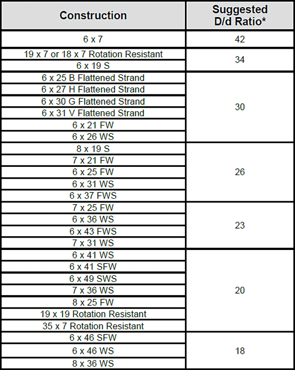
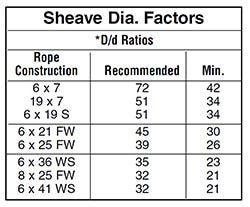
The relationship between sheave diameter and rope diameter is a critical factor that is used to estimate the rope’s fatigue resistance or relative service life. It is expressed in the D/d ratio mentioned earlier in which D is the pitch diameter of the sheave and d is the diameter of the rope. Table 1 lists suggested minimum D/d values for various rope constructions. Smaller values can affect rope life. Table 2 (on next page) shows the effect of rope construction and D/d on service life.
These D/d ratios are based on sheave and drum diameters being approximately 400 times the outer wire diameter of the rope. For rope constructions not listed, consult your Lifting Specialist.
A new wire rope requires careful installation and following all the appropriate guidelines previously noted. After the rope is installed and the ends secured in the correct manner, the equipment should be started carefully and then permitted to run through a cycle of operation at very slow speed.
During this trial operation, closely watch all working parts—sheaves, drums, rollers—to make certain that the rope runs freely, and without any possible obstructions as it makes its way through the system. If no problems appear in running the rope, the next step should include several repetitions of the normal operational cycle under increasing loads and speeds.
This procedure allows the component parts of the new rope to make a gradual adjustment to the actual operating conditions. Taking the time and effort to perform these breaking-in procedures should result in obtaining the optimum service life from the wire rope.
This service life curve only takes into account bending and tensile stresses. This curve can be utilized to predict comparative service life of a specific wire rope with varying D/d ratios.
That resultant comparison is illustrated by the following example: A rope working with a D/d ratio of 26 has a relative service life of 17. If the same rope works over a sheave that increases its D/d ratio to 35, the relative service life increases to 32.
Precision CNC machining, turning and milling services. Capabilities include bending, waterjet cutting, routing, forming, drilling, casting, urethane molding, additive manufacturing (3D printing) and welding. Works with rubber, polyurethane, nylon, acetal, polycarbonate, acrylic, fiberglass reinforced plastics (FRP), laminates, PVC and other plastic materials. Manufacturer of custom and standard truck parts, bumpers, gaskets, seals, bushings, trays, anti-vibration or manifold grommets, caps and vibration mounts. Bearings, sheaves, pulleys, channels, nozzles, profiles, sprockets, outrigger pads, strip doors, elbows, rollers, matting, barriers, ceramic and truck liners are provided. Prototypes, short and high runs production volumes are offered. Materials are available in the form of sheets, tubes and rods. Serves agricultural, aggregate, biomass, construction, marine, port, material handling, mining, oil, gas, retail, transportation, automotive, food and beverage industries.
Wire rope and cabling is very widely used throughout industry in a variety of applications. Failures of such ropes however continue to take place, often due to misuse or lack of understanding of the constraints under which wire ropes operate. Users are referred to the appropriate suppliers who can advise them of the optimum operating conditions, but what is often abused is the size of the sheave wheel selected for a particular wire rope diameter. Many suppliers specify that the ratio of sheave diameter to rope diameter should be in the range 20 to 30 (i.e. D/d = 20 to 30). However at small rope diameters (6 to 10mm), this stringency can be relaxed to ratios closer to 10. Research studies conducted, have shown that for a 13mm diameter wire rope, simply changing a pulley diameter from the recommended 300mm to 150mm diameter led to a six fold decrease in fatigue life of the rope – a significant loss. Manufacturers’ tables should be consulted for all applications and their advice headed (they are seldom overly conservative).
In addition, wear or incorrect machining of the grooves of the sheave is also a common problem, and worn sheaves contribute to significant wear of wire ropes and should be re-machined as soon as any wear (as measured using a suitable groove gauge) becomes apparent. Similarly inappropriate fleet angles (angle of wire running from the drum to a guide pulley/sheave) can also cause significant wear and shorten fatigue life. Fleet angles are specified at typically less than 1-2 degrees and should be adhered to for optimum fatigue life.

Wire sheaves have been around for centuries, being very useful tools for various lifting, pulling and suspension applications. Read on for some basic use, maintenance and safety information on today’s wire rope sheaves.
A sheave is basically a wheel with a groove or track on it which guides the wire rope over it. In its simplistic form, wire rope passes over a sheave and connects to the load. The other end of the wire is attached to a pulling device, such as a winch, to gain mechanical advantage. The threaded line over the sheave completes the device. To prevent the wire rope from leaving the groove, the minimum depth of the groove should be the thickness of the rope or cable.
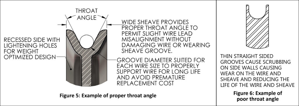
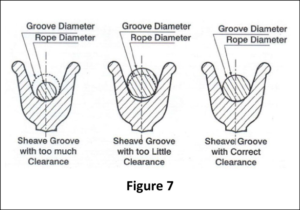
Although the rope sheave has a simple construction, its function is a little bit complicated. You have to determine the exact wire rope diameter to choose the correct sheave size. The groove on a sheave should be flared and slightly larger than the nominal diameter of the rope. If the groove is too big the wire will flatten under load; if the groove is too small, the rope will be pinched.
Wire sheaves or pulleys change the direction of the force or increase the pressure to a load. The wire never lays straight in the groove of a sheave because the attached load moves from slide to slide. The movement causes the wire rope to rub against the sides of the sheave, which in turn causes wear.
Like any mechanical system, rope sheaves require maintenance. Here’s some good points to bear in mind:Always check the sheaves to avoid delay in your operations.
Pay attention to the sheave groove and the edges of the flange. Any fractures or cracks can cut the rope during operation. General wear on the surface of the sheave could result in a reduction in groove surface, creating an uneven load-bearing surface.
Centuries ago, sheaves were commonly used for sailing. Today, wire rope sheaves find usefulness in many industrial and lifting applications. And Wire Rope Australia actively participates in many of these industries as a supplier of wire rope, wire rope sheaves and a full range of wire rope fittings.
Bear Equipment originally specialized in excavator and undercarriage crane parts. As our customers" demands for the supply of replacement wire rope pulley parts grew, we began specializing in sheaves. Today, wire rope sheaves is our primary business.
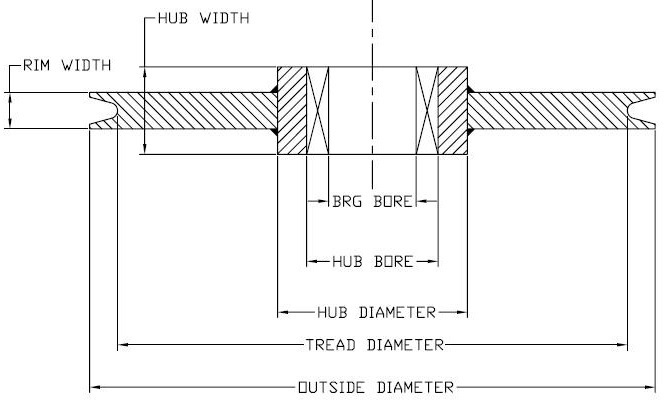
The specifications we require to custom manufacture your wire rope sheaves are: Outside Diameter, Finished Bore, Rim Width, Hub Width, Shaft Size, Groove/Tread Diameter, Hub Diameter, Rope Diameter, Pitch Diameter, Groove Depth. Other important details can be found on our Sheaves Order Form. Please call or email if you require any assistance.
Noticing an increasing demand for replacement wire rope sheaves used in cranes, Bear Equipment began specializing in the manufacture and supply of wire rope sheaves to suit all industries and applications. We have the capability to manufacture your sheaves to your design and specifications or you can choose your wire-rope sheave from our large inventory. We know you"ll be pleased with our customer service, quick delivery, and our quality product at a competitive price.
The specifications we require to custom manufacture your wire rope sheaves are: Outside Diameter, Finished Bore, Rim Width, Hub Width, Shaft Size, Groove/Tread Diameter, Hub Diameter, Rope Diameter, Pitch Diameter, Groove Depth. Other important details can be found on our Sheaves Order Form. Please call or email if you require any assistance.
Manufacturing sheaves for wire rope is our primary business. We have the capability to manufacture your sheaves to your design and specifications or you can choose your wire rope sheave from our large inventory.
Our wire rope sheaves are made from quality materials and machined to precise dimensions and tolerances in order to meet our high standards. In addition, we offer many other options to satisfy your sheave requirements, including choice of material, heat treating of the groove, case hardening, grease fittings, keyways and set screws, plating and many more. We also carry bearings and bronze bushings.
Choose from our stock sheave sizes or we can manufacture your wire rope sheaves to your design and specifications. SELECTING FROM OUR STOCK SIZES OFFERS YOU QUICKER DELIVERY AND ECONOMY, or we can stock for your ongoing requirements. Please complete this form and we will gladly quote.
2" to 4" Wire Rope Pulleys are furnished with a 7/8" stock bore to receive a press fit on the 7/8" outside diameter powdered metal bushing sizes. Pulleys and bushings should be ordered separately by stock number.
5" to 10" Wire Rope Pulleys are furnished with a 1-1/4" stock bore to receive a press fit on the 1-1/4" outside diameter powdered metal bushing sizes. Pulleys and bushings should be ordered separately by stock number.
Selecting the right size for sheaves will help prevent frequent wire rope damage which in some instances occurs after just one run. Many common operational issues including the wireline getting dislodged or losing its strength are caused by improper sheave sizing and alignment problems. Our experts offer 3 valuable tips to eliminate stress failure, improve equipment safety and efficiency, as well as increase the lifespan of your sheaves and wire rope.
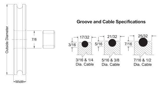
Pay attention to sheave groove size and diameter: When sheaves for your wire rope are too large or too small, there is greater stress on both resulting in spooling trouble and premature wear. For instance, grooves that are too large have proven to cause the wire rope to flatten and unbalance leading to the wire breaking. When properly sized, the groove provides maximum support to the rope lowering the sheave bearing pressure and increasing sheave and rope lifespan. Typically the groove diameter should exceed that of the wire rope by 5% while groove depth should be one-and-a-half times the rope diameter. A groove angle between 30° and 45° offers the best support for the wire rope. Specific dimensions and angles may vary depending on your application.
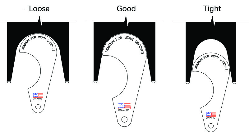
Ensure sheave groove hardness: The hardness of sheaves is a factor that is often overlooked. Since the wire rope is hard, the pressure it exerts on the groove can lead to corrugations if the sheave is not properly hardened. To avoid this, ensure your steel cable sheaves are flame hardened. (A simple way to determine if your grooves are worn out is by using a sheave gauge.) At Rockett Inc., we can provide flame hardening for wear resistance along the contact area.
Correct sheave groove alignment: Poor alignment of your sheaves wears out the wire rope and sheave flange. This is because the rope comes into constant contact with the flange creating stress on the rope, abrasion damage and fatigue breaks. Any alignment issues should be corrected immediately.
To avoid operational problems, opt for custom made steel sheaves. This way the sheaves for your wire ropes are tailored to your specific requirements instead of the other way around. As an experienced sheave manufacturer with a state-of-the-art facility in Mississippi, Rockett Inc. offers comprehensive custom solutions for diverse industrial and commercial needs.
Should you have a specific requirement, our experienced engineers can work closely with you to design and manufacture the product your application requires. Precision engineering and state-of-the-art metal fabrication equipment result in a closer tolerance fit to the wire rope to reduce fatigue and wear. Inspection at every stage of our manufacturing process ensures that the final output meets your specifications.
Need assistance with designing sheaves for wire rope? We are always happy to help. Our team can work directly from your drawings and specifications, or offer 3D CAD design and engineering support optimized for practical, cost-effective results. Over the years, we have produced the most diverse range of custom steel cable sheaves for our clients across the globe. Having the ISO 9001:2008 Certification means we take pride in quality and customer satisfaction.

Original equipment wire rope and replacement wire rope must be selected and installed in accordance with the requirements of this section. Selection of replacement wire rope must be in accordance with the recommendations of the wire rope manufacturer, the equipment manufacturer, or a qualified person.
Wire rope design criteria: Wire rope (other than rotation resistant rope) must comply with either Option (1) or Option (2) of this section, as follows:
Option (1). Wire rope must comply with section 5-1.7.1 of ASME B30.5-2004 (incorporated by reference, see § 1926.6) except that section"s paragraph (c) must not apply.
Option (2). Wire rope must be designed to have, in relation to the equipment"s rated capacity, a sufficient minimum breaking force and design factor so that compliance with the applicable inspection provisions in § 1926.1413 will be an effective means of preventing sudden rope failure.
Type I rotation resistant wire rope ("Type I"). Type I rotation resistant rope is stranded rope constructed to have little or no tendency to rotate or, if guided, transmits little or no torque. It has at least 15 outer strands and comprises an assembly of at least three layers of strands laid helically over a center in two operations. The direction of lay of the outer strands is opposite to that of the underlying layer.
Type II rotation resistant wire rope ("Type II"). Type II rotation resistant rope is stranded rope constructed to have significant resistance to rotation. It has at least 10 outer strands and comprises an assembly of two or more layers of strands laid helically over a center in two or three operations. The direction of lay of the outer strands is opposite to that of the underlying layer.
Type III rotation resistant wire rope ("Type III"). Type III rotation resistant rope is stranded rope constructed to have limited resistance to rotation. It has no more than nine outer strands, and comprises an assembly of two layers of strands laid helically over a center in two operations. The direction of lay of the outer strands is opposite to that of the underlying layer.
Type I must have an operating design factor of no less than 5, except where the wire rope manufacturer and the equipment manufacturer approves the design factor, in writing.
When Types II and III with an operating design factor of less than 5 are used (for non-duty cycle, non-repetitive lifts), the following requirements must be met for each lifting operation:
A qualified person must inspect the rope in accordance with § 1926.1413(a). The rope must be used only if the qualified person determines that there are no deficiencies constituting a hazard. In making this determination, more than one broken wire in any one rope lay must be considered a hazard.
Each lift made under § 1926.1414(e)(3) must be recorded in the monthly and annual inspection documents. Such prior uses must be considered by the qualified person in determining whether to use the rope again.
Rotation resistant ropes may be used as boom hoist reeving when load hoists are used as boom hoists for attachments such as luffing attachments or boom and mast attachment systems. Under these conditions, all of the following requirements must be met:
The requirements in ASME B30.5-2004 sections 5-1.3.2(a), (a)(2) through (a)(4), (b) and (d) (incorporated by reference, see § 1926.6) except that the minimum pitch diameter for sheaves used in multiple rope reeving is 18 times the nominal diameter of the rope used (instead of the value of 16 specified in section 5-1.3.2(d)).
The operating design factor for these ropes must be the total minimum breaking force of all parts of rope in the system divided by the load imposed on the rope system when supporting the static weights of the structure and the load within the equipment"s rated capacity.
Wire rope clips used in conjunction with wedge sockets must be attached to the unloaded dead end of the rope only, except that the use of devices specifically designed for dead-ending rope in a wedge socket is permitted.
Prior to cutting a wire rope, seizings must be placed on each side of the point to be cut. The length and number of seizings must be in accordance with the wire rope manufacturer"s instructions.
(a) Factor of Safety. All rope to be used for regular hoisting shall be wire rope providing a factor of safety not less than five to one for material hoist and ten to one for personnel hoist when new, which shall be calculated by dividing the breaking strength of the wire rope as given in the manufacturer"s published tables, by the total load to be hoisted including the total weight of the wire rope in the shaft when fully let out, plus a proper allowance for impact and acceleration.
The acceleration allowance shall be in accordance with manufacturer"s recommendations, but in all cases the factor of safety of five or more must be maintained when the load, used in determining it, is greater than the actual weight by a percentage that is numerically three times the acceleration or deceleration, whichever is greatest. For example, a deceleration or acceleration of two feet per second that increases the load would require use of an effective load 6 percent greater than the actual weight, in the calculation of a factor of safety.
(b) Wire Rope Fastenings. Every wire rope used for hoisting shall be securely fastened at both ends and when in use shall not be fully unwound; at least three full turns shall remain on the drum so as to protect the end fastening at drum from overload. The wire rope end at the cage, skip or bucket shall be securely fastened by a properly made tapered socket joint, by an eye in the wire rope made with an oval thimble and wire rope clips, or by another method acceptable to the Division for this or similar service. If the wire rope clip method is used, the spacing and number used shall be as shown in Table - 1 for U-Bolts and in Table - 2 for Fist-Grip clips based upon using RRL or RLL wire rope, 6 x 19 or 6 x 37 Class, FC or IWRC; IPS or XIP. If Seale construction or similar large outer wire type construction in the 6 x 19 Class is to be used for sizes 1 inch and larger, add one additional clip. If a pulley (sheave) is used for turning back the wire rope, add one additional clip.
The number of clips shown also applies to rotation-resistant RRL wire rope, 8 x 19 Class, IPS, XIP, sizes 1-1/2 inch and smaller; and to rotation-resistant RRL wire rope, 19 x 7 Class, IPS, XIP (sizes 1-3/4 inch and smaller for U-Bolts and size 1-1/2 inch and smaller for Fist Grips).
(d) Splicing. Spliced wire rope shall not be used, except that the end may be attached to the load by the thimble and/or clip method, as provided in subsection (b) of this section.
(1) A safety hook, shackle or other means providing closed design protection shall form the attachment between rope and a bucket, cage, skip or load. The attachment shall be made so that the force of the hoist pull, vibration, misalignment, release of lift force, or impact will not disengage the connection. Moused or open-throat hooks with light safety latches do not meet this requirement.
(2) All wire rope fittings and connections shall be in accordance with the manufacturers" specifications and compatible with the type of wire rope used.
(g) Drum Flanges. The drum of any hoist used for hoisting shall have flanges which extend at least 2 inches radially beyond the last layer of rope when all the rope is coiled on the drum.


 8613371530291