
splicing steel wire rope factory

We custom manufacture wire rope assemblies (endless loop) for conveyor lines. Our specialty is the Long splice. The Long splice is used to create a continuous or endless loop of wire rope cable frequently utilized on conveyor systems. The splice is a difficult multi-step labor intensive process in which two wire rope cable ends are joined end to end and the strands are intertwined to merge the two individual wire rope cable ropes ends.
Our proven experience can be viewed first hand in the quality of our wire rope cable splices we perform regularly for diverse clientele in the Unites States and around the world. For assistance with your unique wire rope conveyor cable splicing needs, please complete theor call us directly at

The termination is fully wetted, smooth and shiny. Conductor contours are discernable. Tubing is tightly shrunk with proper strain relief, overlap and no exposed conductive surfaces.
The termination is fully wetted, smooth and shiny. Conductor contours are discernable. Tubing is tightly shrunk, with proper strain relief, overlap and no exposed conductive surfaces.
The termination is fully wetted, smooth and shiny. Conductor contours are discernable. Tubing is tightly shrunk, with proper strain relief, overlap and no exposed conductive surfaces.
The termination is fully wetted, smooth and shiny. Conductor contours are discernable. Tubing is tightly shrunk, with proper strain relief, overlap and no exposed conductive surfaces.
The termination is fully wetted, smooth and shiny. Tubing is tightly shrunk, with proper strain relief, overlap and no exposed conductive surfaces. Western Union splices are used for solid conductors.

Manufacturer of aluminum swage sleeves including hour glass, oval, thin wall, combo & fiber rope sleeves. Hour glass sleeves range in rope & sleeve size from 1/32 to 1/2, width from .090 to 1.062, height from .136 to 1.625, hole width from .040 to .562, length from 1/4 to 2. Oval sleeves have a rope & sleeve size of 1/16, width of .172, height of .250, hole width of .078 & length of 3/8. Thin wall sleeves range in rope & sleeve size from 3/32 to 5/32, in width from .226 to .375, height from .372 to .562, hole width from .118 to .200 & length from 1/2 to 11/16. Combo sleeves are available with rope & sleeve size of 1/8 x 1/16, width of .343, height of .500, hole widths of .156 & .078 & length of 5/8 or sleeve size of 3/16 x 1/8, width of .430, height of .656, hole widths of .160 & .320 & length of 1. Fiber rope sleeves range in rope & sleeve size from 1/8 to 7/16, width from .250 to .855, height of .388 to 1.35, hold width from .160 to .525 & length from 1/2 to 1 1/4.

As a rigger or end-user of wire rope, it’s important to understand the types of terminations, or treatments, that can be used at the ends of a length of wire rope. These terminations are usually made by forming an eye or attaching a fitting, and are designed to be a permanent end termination on the wire rope where it connects to the load.
Wire rope is an extremely versatile mechanical device that can be used to help support and move an object or load. In the lifting and rigging industries, wire rope is attached to a crane or hoist and fitted with swivels, shackles or hooks to attach to a load and move it in a controlled matter. It can also be used to lift and lower elevators, or as a means of support for suspension bridges or towers.
In this article, we’ll explain what some of the following terms mean and how the can be used to terminate the end of a wire rope cable:Wire rope sockets—spelter sockets, swaged sockets, and wedge sockets
When you understand the construction and specifications of the wire rope you need, as well as the right type of end termination you need, you’ll be able to select the best performing and longest-lasting wire rope for the job at hand.
There are essentially two techniques that can be used to create a termination on a length of wire rope or cable:You can form an eye, or loop, in the wire rope
Eyes, or loops, can be created at one end of a length of wire rope by using a mechanical splice with a swaged sleeve, a hand-tucked splice, or wire rope clips.
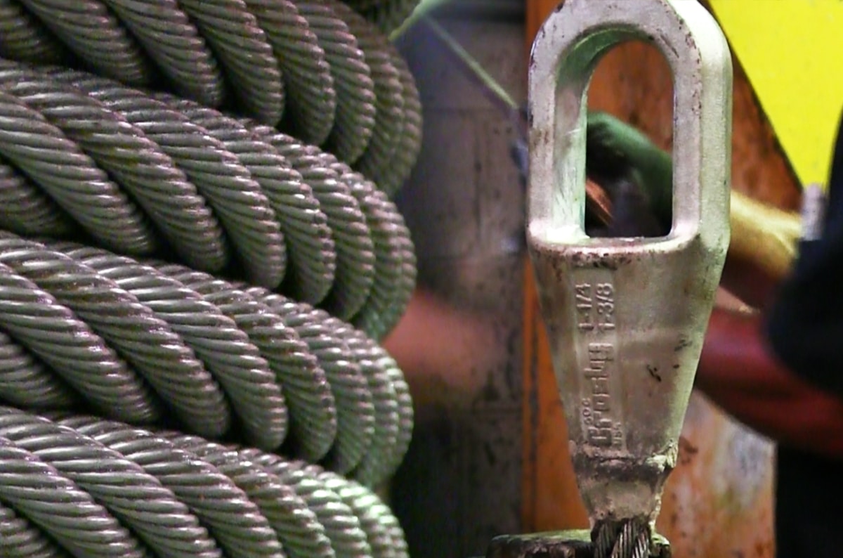
A swaged socket is applied to the end of a wire rope cable and is then forced into place using special dies and a hydraulic machine called a swager. When properly applied with the correct sized fitting, swaged sockets have an efficiency rating of 100% of the breaking strength of the rope.
A poured socket, commonly referred to as a spelter socket, attaches a termination fitting onto the end of a wire rope cable by pouring molten zinc or resin into a socket that then hardens and holds the fitting onto the end of the cable.
Due to the rigidity of this type of termination, the wires of the rope are subject to fatigue where the wires enter the socket, if the poured socket is subject to constant vibration.
Wedge sockets secure the rope to the end attachment by passing it around a grooved, wedge-shaped piece of steel and pulling it down under load into the bowl of the fixture.
Wedge sockets are popular because they can be installed in field and adjusted in field – providing 80% efficiency of rope breaking strength. Wedge sockets are popular in applications where the wire rope may be subjected to abuse and abrasion—particularly in construction and mining applications.
Wire rope clips can be used to form a load bearing eye at the end of a cable or wire rope, or to connect two cables together with a lap splice. Wire rope clips are popular because they can be installed in the field and provide 80% efficiency of the rope breaking strength.
However, the use of wire rope clips is heavily regulated by ASME B30.26 Rigging Hardware. When using wire rope clips, the end user must account for the following:When using U-bolt wire rope clips, the saddle shall be placed on the live end of the wire rope, with the U-bolt on the dead-end side—NEVER SADDLE A DEAD HORSE!
After installation, the connection shall be loaded to at least the expected working load. After unloading, the wire rope clips shall be re-tightened to the torque specifications of the manufacturer or a Qualified Person.
This type of wire rope clip is essentially a U-bolt, two nuts, and a metal base (saddle) that can be made from forged steel or cast iron. Careful consideration and attention must be given to the way U-bolt type wire rope clips are installed.
The base of the wire rope clip is made from forged steel. Forged clips are heated and hammered into the desired shape—resulting in a consistent grain structure in the steel. Forged wire rope clips are used for critical, heavy-duty, overhead loads such as winch lines, crane hoist lines, support lines, guy lines, towing lines, tie downs, scaffolds, etc.
Malleable wire rope clips are used for making eye termination assemblies only with right regular lay wire rope and only for light duty uses with small applied loads, such as hand rails, fencing, guard rails, etc. The base of the wire rope clips is made from malleable cast iron, which may fracture under heavy use and does not have the desirable metal properties of steel, or the beneficial grain structure that a forged base has.
Double saddle wire rope clips consist of two saddles, each with a leg, and two nuts—one used on the top and one on the bottom. Double saddle wire rope clips can be used in either direction, so they take the guesswork out during installation when applying to the live end and the dead end of a piece of wire rope.
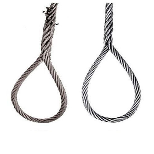
An eye splice may be used to terminate the loose end of a wire rope when forming a loop. The strands of the end of a wire rope are unwound and then the wire is bent around, and the unwrapped strands are then weaved back into the wire rope to form an eye.
A Flemish eye splice is created when the wire rope is opened, and the strands are laid out into two parts. The two strands are looped in opposite directions and then laid back together—forming an eye, or loop, at one end of the wire rope cable. The strands are then rolled back around the rope body and a metal sleeve fitting is slipped over the splice and swaged using hydraulic machinery. This splicing method provides the most efficient use of rope capacity and is highly economical.
A hand tucked splice is formed when the shorter “dead” end is tucked into the longer “live” end of the wire rope—forming an eye. These types of splices allow for easy inspection of the wire rope wires and strands.
When the end of a rope is turned back and formed into an eye, a thimble is often used to keep the shape of the eye, prevent the rope from being crushed, and keep the rope from being bent at a diameter smaller than the rope manufacturer’s recommendations.
The table below will explain the efficiencies of the different types of wire rope end terminations for both independent wire rope core (IWRC) and fiber core (FC) wire rope configurations. Rope efficiency is described as the ratio of a wire rope’s actual breaking strength and the aggregate strength of all individual wires tested separately—usually expressed as a percentage.IWRCFC
*Spelter sockets in smaller rope sizes (usually less than 7/16”) may not always develop 100% efficiency and are not recommended by some rope manufacturers.
When you need to order a replacement wire rope, understanding the right type of end termination will help to make sure you get a direct replacement rope so you can get your project back on track. We hope this article gives you a better understanding of terms related to sockets, wire rope clips, and eye splices and that you understand what type of end termination may be best for your application.
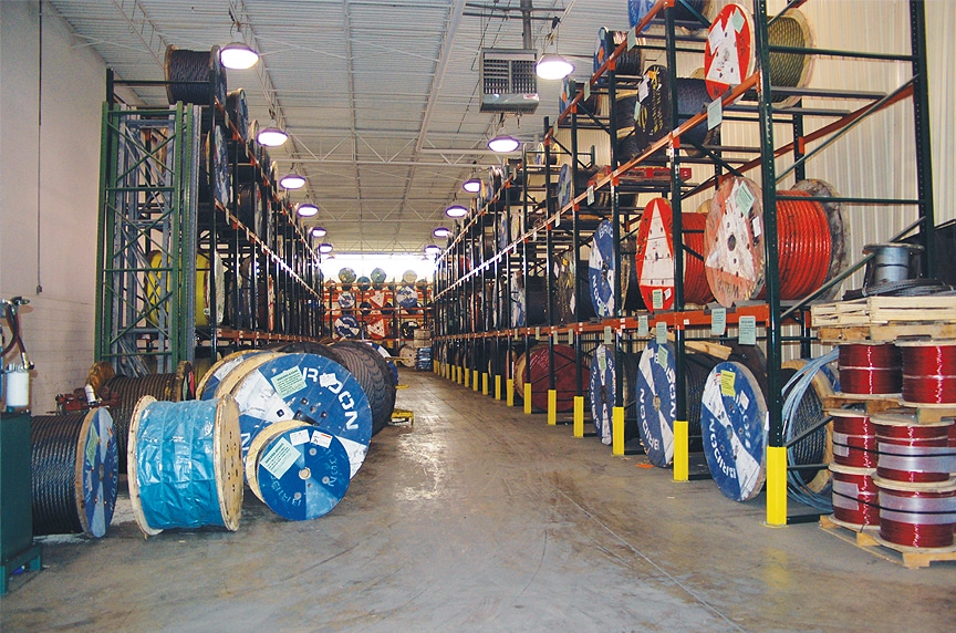
At Mazzella, we offer all different kinds of wire rope from all of the leading manufacturers. We sell the highest-quality domestic and non-domestic rigging products because product quality and operating safety go hand-in-hand. We have one of the largest and most complete inventories of both domestic and non-domestic rigging and lifting products to suit your lifting needs.
We were established in 1961 and since then Sahm-Seilklemmen has produced and distributed products complementing the mechanical splicing of wire ropes. Today we are a leading supplier for wire rope end terminations to the rigging industry and in addition to ferrules, we can supply appropriate accessories and the most diverse services.
Our product range includes ferrules made from aluminium, copper, steel and stainless steel, all manufactured exclusively by us in Germany and USA. As a system supplier, we can provide you not only with the correct ferrule for your application, but also a large range of swaging machines, test beds, cutting & annealing machines and differenttools.

Wire rope splicing is essentially the formation of a knot between two parts of the same rope or between two separate ropes by separating and unravelling the strands and interweaving the threads together to produce a strong joint. Splicing forms a very strong knot which stays secure even if exposed to water.
There are different types of wire rope splicing. The two more common ones areBack or end splicing – This is a type of splicing where rope end strands are directly spliced without making a loop. With this wire rope splicing, rope ends are drawn to a close to prevent fraying.
Eye splicing – This a more popular type of wire rope splicing which involves taking the working end of the rope to form a loop at the end. The end of the rope strands are unraveled, then passed over and under against the lay of the rope to interweave it back into the main length of the rope.
Wire rope splicing maintains almost 95% of the wire rope’s strength. You can employ splicing in three-strand braided ropes, or even in over 12-strand braided ropes.
Splicing lets you create a new rope of any length, alter an existing rope to suit a changing application, or repair a damaged wire rope. There are two main disadvantages to splicing – the expanding thickness of the line at the joint and the distortion in the shape of the rope.
Check the wire rope tools and accessories section of this website for more tools or fill out the enquiry form and let us help with your wire rope splicing needs.

Welcome to AAA Wire Rope & Splicing! If you are looking for high quality lifting and rigging products and first class customer service, you"ve come to the
right place. Since 1962, AAA Wire Rope & Splicing has been serving Southeast Michigan and beyond. Our committment to customer service combined with our daily delivery routes get

We are a leading UK midland based Family run manufacturing Company and stockist of Lifting Equipment, Chain slings, Wire Rope Rigging of all ropes including Anti spin and Crane ropes, Hand splicing of all ropes, and 316 quality Marine equipment, including Architectural, industrial applications.... Read More
“Tough-Lock™” and “Cable-Flex™” slings are uniquely constructed unlike various return wire loop types. Note that our five step manufacturing process, commonly
All “Tough-Lock™” slings adhere and comply with current specifications of OSHA, ASME B30.9c-2000 Wire Rope Technical, and Associated Wire Rope Fabricators.
In stricter senses, the term wire rope refers to a diameter larger than 9.5 mm (3⁄8 in), with smaller gauges designated cable or cords.wrought iron wires were used, but today steel is the main material used for wire ropes.
Historically, wire rope evolved from wrought iron chains, which had a record of mechanical failure. While flaws in chain links or solid steel bars can lead to catastrophic failure, flaws in the wires making up a steel cable are less critical as the other wires easily take up the load. While friction between the individual wires and strands causes wear over the life of the rope, it also helps to compensate for minor failures in the short run.
Wire ropes were developed starting with mining hoist applications in the 1830s. Wire ropes are used dynamically for lifting and hoisting in cranes and elevators, and for transmission of mechanical power. Wire rope is also used to transmit force in mechanisms, such as a Bowden cable or the control surfaces of an airplane connected to levers and pedals in the cockpit. Only aircraft cables have WSC (wire strand core). Also, aircraft cables are available in smaller diameters than wire rope. For example, aircraft cables are available in 1.2 mm (3⁄64 in) diameter while most wire ropes begin at a 6.4 mm (1⁄4 in) diameter.suspension bridges or as guy wires to support towers. An aerial tramway relies on wire rope to support and move cargo overhead.
Modern wire rope was invented by the German mining engineer Wilhelm Albert in the years between 1831 and 1834 for use in mining in the Harz Mountains in Clausthal, Lower Saxony, Germany.chains, such as had been used before.
Wilhelm Albert"s first ropes consisted of three strands consisting of four wires each. In 1840, Scotsman Robert Stirling Newall improved the process further.John A. Roebling, starting in 1841suspension bridge building. Roebling introduced a number of innovations in the design, materials and manufacture of wire rope. Ever with an ear to technology developments in mining and railroading, Josiah White and Erskine Hazard, principal ownersLehigh Coal & Navigation Company (LC&N Co.) — as they had with the first blast furnaces in the Lehigh Valley — built a Wire Rope factory in Mauch Chunk,Pennsylvania in 1848, which provided lift cables for the Ashley Planes project, then the back track planes of the Summit Hill & Mauch Chunk Railroad, improving its attractiveness as a premier tourism destination, and vastly improving the throughput of the coal capacity since return of cars dropped from nearly four hours to less than 20 minutes. The decades were witness to a burgeoning increase in deep shaft mining in both Europe and North America as surface mineral deposits were exhausted and miners had to chase layers along inclined layers. The era was early in railroad development and steam engines lacked sufficient tractive effort to climb steep slopes, so incline plane railways were common. This pushed development of cable hoists rapidly in the United States as surface deposits in the Anthracite Coal Region north and south dove deeper every year, and even the rich deposits in the Panther Creek Valley required LC&N Co. to drive their first shafts into lower slopes beginning Lansford and its Schuylkill County twin-town Coaldale.
The German engineering firm of Adolf Bleichert & Co. was founded in 1874 and began to build bicable aerial tramways for mining in the Ruhr Valley. With important patents, and dozens of working systems in Europe, Bleichert dominated the global industry, later licensing its designs and manufacturing techniques to Trenton Iron Works, New Jersey, USA which built systems across America. Adolf Bleichert & Co. went on to build hundreds of aerial tramways around the world: from Alaska to Argentina, Australia and Spitsbergen. The Bleichert company also built hundreds of aerial tramways for both the Imperial German Army and the Wehrmacht.
In the last half of the 19th century, wire rope systems were used as a means of transmitting mechanical powercable cars. Wire rope systems cost one-tenth as much and had lower friction losses than line shafts. Because of these advantages, wire rope systems were used to transmit power for a distance of a few miles or kilometers.
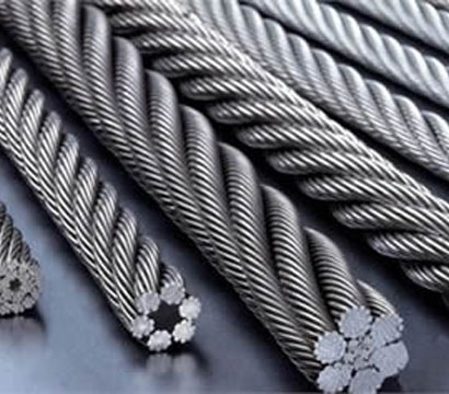
Steel wires for wire ropes are normally made of non-alloy carbon steel with a carbon content of 0.4 to 0.95%. The very high strength of the rope wires enables wire ropes to support large tensile forces and to run over sheaves with relatively small diameters.
In the mostly used parallel lay strands, the lay length of all the wire layers is equal and the wires of any two superimposed layers are parallel, resulting in linear contact. The wire of the outer layer is supported by two wires of the inner layer. These wires are neighbors along the whole length of the strand. Parallel lay strands are made in one operation. The endurance of wire ropes with this kind of strand is always much greater than of those (seldom used) with cross lay strands. Parallel lay strands with two wire layers have the construction Filler, Seale or Warrington.
In principle, spiral ropes are round strands as they have an assembly of layers of wires laid helically over a centre with at least one layer of wires being laid in the opposite direction to that of the outer layer. Spiral ropes can be dimensioned in such a way that they are non-rotating which means that under tension the rope torque is nearly zero. The open spiral rope consists only of round wires. The half-locked coil rope and the full-locked coil rope always have a centre made of round wires. The locked coil ropes have one or more outer layers of profile wires. They have the advantage that their construction prevents the penetration of dirt and water to a greater extent and it also protects them from loss of lubricant. In addition, they have one further very important advantage as the ends of a broken outer wire cannot leave the rope if it has the proper dimensions.
Stranded ropes are an assembly of several strands laid helically in one or more layers around a core. This core can be one of three types. The first is a fiber core, made up of synthetic material or natural fibers like sisal. Synthetic fibers are stronger and more uniform but cannot absorb much lubricant. Natural fibers can absorb up to 15% of their weight in lubricant and so protect the inner wires much better from corrosion than synthetic fibers do. Fiber cores are the most flexible and elastic, but have the downside of getting crushed easily. The second type, wire strand core, is made up of one additional strand of wire, and is typically used for suspension. The third type is independent wire rope core (IWRC), which is the most durable in all types of environments.ordinary lay rope if the lay direction of the wires in the outer strands is in the opposite direction to the lay of the outer strands themselves. If both the wires in the outer strands and the outer strands themselves have the same lay direction, the rope is called a lang lay rope (from Dutch langslag contrary to kruisslag,Regular lay means the individual wires were wrapped around the centers in one direction and the strands were wrapped around the core in the opposite direction.
Multi-strand ropes are all more or less resistant to rotation and have at least two layers of strands laid helically around a centre. The direction of the outer strands is opposite to that of the underlying strand layers. Ropes with three strand layers can be nearly non-rotating. Ropes with two strand layers are mostly only low-rotating.
Stationary ropes, stay ropes (spiral ropes, mostly full-locked) have to carry tensile forces and are therefore mainly loaded by static and fluctuating tensile stresses. Ropes used for suspension are often called cables.
Track ropes (full locked ropes) have to act as rails for the rollers of cabins or other loads in aerial ropeways and cable cranes. In contrast to running ropes, track ropes do not take on the curvature of the rollers. Under the roller force, a so-called free bending radius of the rope occurs. This radius increases (and the bending stresses decrease) with the tensile force and decreases with the roller force.
Wire rope slings (stranded ropes) are used to harness various kinds of goods. These slings are stressed by the tensile forces but first of all by bending stresses when bent over the more or less sharp edges of the goods.
Technical regulations apply to the design of rope drives for cranes, elevators, rope ways and mining installations. Factors that are considered in design include:
Donandt force (yielding tensile force for a given bending diameter ratio D/d) - strict limit. The nominal rope tensile force S must be smaller than the Donandt force SD1.
The wire ropes are stressed by fluctuating forces, by wear, by corrosion and in seldom cases by extreme forces. The rope life is finite and the safety is only ensured by inspection for the detection of wire breaks on a reference rope length, of cross-section loss, as well as other failures so that the wire rope can be replaced before a dangerous situation occurs. Installations should be designed to facilitate the inspection of the wire ropes.
Lifting installations for passenger transportation require that a combination of several methods should be used to prevent a car from plunging downwards. Elevators must have redundant bearing ropes and a safety gear. Ropeways and mine hoistings must be permanently supervised by a responsible manager and the rope must be inspected by a magnetic method capable of detecting inner wire breaks.
The end of a wire rope tends to fray readily, and cannot be easily connected to plant and equipment. There are different ways of securing the ends of wire ropes to prevent fraying. The common and useful type of end fitting for a wire rope is to turn the end back to form a loop. The loose end is then fixed back on the wire rope. Termination efficiencies vary from about 70% for a Flemish eye alone; to nearly 90% for a Flemish eye and splice; to 100% for potted ends and swagings.
When the wire rope is terminated with a loop, there is a risk that it will bend too tightly, especially when the loop is connected to a device that concentrates the load on a relatively small area. A thimble can be installed inside the loop to preserve the natural shape of the loop, and protect the cable from pinching and abrading on the inside of the loop. The use of thimbles in loops is industry best practice. The thimble prevents the load from coming into direct contact with the wires.
A wire rope clip, sometimes called a clamp, is used to fix the loose end of the loop back to the wire rope. It usually consists of a U-bolt, a forged saddle, and two nuts. The two layers of wire rope are placed in the U-bolt. The saddle is then fitted to the bolt over the ropes (the saddle includes two holes to fit to the U-bolt). The nuts secure the arrangement in place. Two or more clips are usually used to terminate a wire rope depending on the diameter. As many as eight may be needed for a 2 in (50.8 mm) diameter rope.
The mnemonic "never saddle a dead horse" means that when installing clips, the saddle portion of the assembly is placed on the load-bearing or "live" side, not on the non-load-bearing or "dead" side of the cable. This is to protect the live or stress-bearing end of the rope against crushing and abuse. The flat bearing seat and extended prongs of the body are designed to protect the rope and are always placed against the live end.
The ends of individual strands of this eye splice used aboard a cargo ship are served with natural fiber cord after splicing to help protect seamens" hands when handling.
An eye splice may be used to terminate the loose end of a wire rope when forming a loop. The strands of the end of a wire rope are unwound a certain distance, then bent around so that the end of the unwrapped length forms an eye. The unwrapped strands are then plaited back into the wire rope, forming the loop, or an eye, called an eye splice.
A Flemish eye, or Dutch Splice, involves unwrapping three strands (the strands need to be next to each other, not alternates) of the wire and keeping them off to one side. The remaining strands are bent around, until the end of the wire meets the "V" where the unwrapping finished, to form the eye. The strands kept to one side are now re-wrapped by wrapping from the end of the wire back to the "V" of the eye. These strands are effectively rewrapped along the wire in the opposite direction to their original lay. When this type of rope splice is used specifically on wire rope, it is called a "Molly Hogan", and, by some, a "Dutch" eye instead of a "Flemish" eye.
Swaging is a method of wire rope termination that refers to the installation technique. The purpose of swaging wire rope fittings is to connect two wire rope ends together, or to otherwise terminate one end of wire rope to something else. A mechanical or hydraulic swager is used to compress and deform the fitting, creating a permanent connection. Threaded studs, ferrules, sockets, and sleeves are examples of different swaged terminations.
A wedge socket termination is useful when the fitting needs to be replaced frequently. For example, if the end of a wire rope is in a high-wear region, the rope may be periodically trimmed, requiring the termination hardware to be removed and reapplied. An example of this is on the ends of the drag ropes on a dragline. The end loop of the wire rope enters a tapered opening in the socket, wrapped around a separate component called the wedge. The arrangement is knocked in place, and load gradually eased onto the rope. As the load increases on the wire rope, the wedge become more secure, gripping the rope tighter.
Poured sockets are used to make a high strength, permanent termination; they are created by inserting the wire rope into the narrow end of a conical cavity which is oriented in-line with the intended direction of strain. The individual wires are splayed out inside the cone or "capel", and the cone is then filled with molten lead-antimony-tin (Pb80Sb15Sn5) solder or "white metal capping",zincpolyester resin compound.
Donald Sayenga. "Modern History of Wire Rope". History of the Atlantic Cable & Submarine Telegraphy (atlantic-cable.com). Archived from the original on 3 February 2014. Retrieved 9 April 2014.

La présente invention concerne un procédé de fabrication de câble en boucle fermée par épissurage, ainsi que la boucle fermée ainsi obtenue qui est plus particulièrement destinée à être intégrée dans une installation de transport par câbles utilisant des câbles tracteurs ou porteurs-tracteurs, sans pour autant y être limitée.The present invention relates to a closed-loop cable manufacturing process by splicing, as well as the closed loop thus obtained which is more particularly intended to be integrated in a cable transport installation using tractor or carrier-tractor cables, without however be limited.
Dans le cadre de la présente invention, on entend par zone d"épissure, une zone comprenant un nœud d"épissure et les deux portions de câbles immédiatement adjacentes à ce nœud, le long desquelles les deux torons noués ont été rentrés à la place de l"âme du câble. In the context of the present invention, splicing zone is understood to mean an area comprising a splicing knot and the two portions of cables immediately adjacent to this knot, along which the two knotted strands have been retracted in place of the soul of the cable.
Ces vibrations, dont la génération est inhérente à l"épissurage des câbles de traction ou porteurs-tracteurs selon l"état de l"art, peuvent toutefois se trouver être de nature à perturber l"environnement de celle-ci (par exemple : génération de bruit à proximité d"habitations) et/ou à accélérer l"usure ou la fatigue de certains de ses composants et en particulier du câble lui-même, ou des composants de l"appareil sur lequel la boucle de câble est utilisée. These vibrations, the generation of which is inherent in the splicing of traction cables or tractor-carriers according to the state of the art, can however be found to be of a nature to disturb the environment of this one (for example: generation noise near homes) and / or accelerate the wear or fatigue of some of its components and in particular the cable itself, or components of the device on which the cable loop is used.
Le but de la présente invention est donc de remédier à ces inconvénients en proposant un procédé d"épissurage permettant d"obtenir un câble en boucle fermée présentant une épissure d"une très grande régularité géométrique, afin de réduire très fortement voire de faire totalement disparaître les vibrations générées par cette zone et de prolonger la durée de vie de ce câble. The purpose of the present invention is therefore to overcome these disadvantages by proposing a splicing process for obtaining a closed loop cable having a splice of a very high geometric regularity, in order to reduce very strongly or even to completely disappear vibrations generated by this area and extend the life of this cable.
- on raccourcit les extrémités des torons à insérer à la place de l"âme de part et d"autre des nœuds d"épissure, de telle sorte qu"il existe un volume libre entre les extrémités et l"âme une fois celles-ci insérées à l"intérieur du câble, volume que l"on remplit ensuite de polymère lors du surmoulage,the ends of the strands to be inserted into the place of the core on either side of the splicing knots are shortened, so that there is a free volume between the ends and the core once these inserted inside the cable, which volume is then filled with polymer during overmolding,
Dans le cadre de la présente invention, on désignera par boucle fermée, une boucle sans fin obtenue par épissurage d"une extrémité d"un câble sur l"autre extrémité de ce même câble, ces deux extrémités étant ramenées l"une en face de l"autre. Ce terme ne recouvre en particulier pas les câbles présentant une boucle terminale, telle qu"une élingue par exemple.The closed-loop cable manufacturing method according to the invention can advantageously be used for splicing a traction cable comprising a monobloc core carrying a plurality of outer strands consisting of steel wires, these strands being most often six in number, made according to the patent application No. PCT / FR12 / 000152 in the name of the applicant and will be described later, by way of illustration but not limitation, with reference to this application. In the context of the present invention, the term closed loop, an endless loop obtained by splicing an end of a cable on the other end of the same cable, these two ends being brought to one opposite of the other. This term does not cover in particular cables having a terminal loop, such as a sling for example.
Dans son principe, l"épissurage consiste donc à "marier" les deux extrémités d"un câble en remplaçant dans chacune d"elles, dans le cas d"un nombre pair de torons, la moitié des torons de l"une par des torons de l"autre et vice versa et en insérant l"extrémité de ces torons à l"intérieur du câble dans une zone où on a ôté l"âme au préalable, après avoir effectué un nœud entre chaque paire de torons concourants. Dans le cas d"un nombre impair de torons, on replacera dans l"une des extrémités de câble à réunir un nombre de torons plus élevé de un que dans l"autre, les deux nombres de torons remplacés dans l"une et l"autre des extrémités correspondant aux deux nombre entiers consécutifs encadrant la valeur égale à la moitié du nombre de torons du câble. Du fait de l"exécution des nœuds entre paires de torons concourants, et dans une moindre mesure de la rentrée des torons noués à l"intérieur du câble, il se produit dans la zone d"épissure diverses augmentations de diamètre plus ou moins ponctuelles de diamètre pouvant atteindre jusqu"à de 10 % du diamètre nominal du câble, l"état de l"art actuel imposant de ne pas dépasser cette valeur. In principle, splicing thus consists in "marrying" the two ends of a cable by replacing in each of them, in the case of an even number of strands, half of the strands of one by strands. the other and vice versa and inserting the end of these strands inside the cable in an area where the soul was removed beforehand, after making a node between each pair of concurrent strands. In the case of an odd number of strands, one of the cable ends will be put back into a higher number of strands than the other, the two numbers of strands replaced in one and the other. other ends corresponding to two consecutive integers framing the value equal to half the number of strands of the cable. Because of the execution of the nodes between pairs of concurrent strands, and to a lesser extent the return of the strands knotted inside the cable, there occur in the splice area various increases in diameter more or less point of diameter up to 10% of the nominal cable diameter, the current state of the art imposing not to exceed this value.
L"ensemble de l"opération d"épissurage nécessite généralement une dizaine d"opérateurs. The entire splicing operation generally requires about ten operators.
longueur en fonction, notamment, du diamètre du câble. Pour des remontées mécaniques, la longueur totale d"une épissure est égale à 1 200 fois le diamètre nominal du câble. Ainsi, pour un câble de diamètre 54 mm, cela représente donc presque 65 m de long.In detail, the manufacture of a closed loop cable by splicing conventionally begins with the preparation of the two areas of the cable to be patched by ligating each of the ends. This ligation is generally done using metal wires positioned respectively at half the estimated length of the splicing zone, in order to precisely position the "marriage" zone of the two ends of the cable. The person skilled in the art knows how to determine this length depending, in particular, the diameter of the cable. For lifts, the total length of a splice is 1,200 times the nominal cable diameter. Thus, for a 54 mm diameter cable, this is almost 65 m long.
classiquement être constitués d"un assemblage de fils de diamètres différents enroulés en hélice autour d"un fil central. Ils sont de préférence métalliques et de façon plus particulièrement préférée en acier. La partie centrale de l"âme du câble peut comprendre en outre un toron. Ce toron peut classiquement être constitué d"un assemblage de fils de diamètres différents enroulés en hélice autour d"un fil central. Il est de préférence métallique et de façon plus particulièrement préféré en acier. Enfin, l"âme du câble peut également comprendre des fibres, métalliques ou non, insérées longitudinalement dans l"âme.Referring now to a cable 1 made according to the application No. PCT / FR12 / 000152 and as shown in Figure 1, it can be seen that it comprises a monobloc core 2 extended by six fins 4 between which come s" insert six strands 3. Strands 3 can conventionally be constituted by an assembly of son of different diameters wound helically around a central wire. They are preferably metallic and more preferably steel. The central portion of the cable core may further comprise a strand. This strand can conventionally consist of an assembly of wires of different diameters wound helically around a central wire. It is preferably metallic and more particularly preferably steel. Finally, the core of the cable may also comprise fibers, metal or not, inserted longitudinally in the core.
chacun des torons à rentrer de part et d"autre des nœuds à exécuter entre torons concourants deux à deux. Chaque aspect de l"invention peut être mis en oeuvre séparément ou en combinaison, en particulier, le surmoulage de chacun des torons à rentrer peut être avantageusement utilisé lors de l"épissurage des câbles porteurs ou porteurs-tracteurs selon l"état de l"art.In order to further improve the geometrical regularity of the splice, one aspect of the invention consists in adding a step of overmolding each splice zone, using a polymer, such as a thermosetting polymer bivariate. component, for example a polyurethane of appropriate grade. Another aspect of the invention, which will be described in more detail a little further, is to add an overmolding step around each of the strands to return from both sides of the nodes to be executed between strands concurrent two by two. Each aspect of the invention can be implemented separately or in combination, in particular, the overmolding of each of the strands to be returned can be advantageously used during the splicing of carrier or carrier-tractors according to the state of the art.
Dans un mode de réalisation préféré, on surmoule la zone d"épissure de façon partielle, de telle sorte que la partie supérieure des torons ne soit pas recouverte par ce polymère, ce qui évite d"en augmenter le diamètre. In a preferred embodiment, the splicing zone is partially overmolded, so that the upper part of the strands is not covered by this polymer, which avoids increasing the diameter thereof.
Ces cales sont réalisées dans un matériau suffisamment dur et résistant dans le temps, par exemple dans des métaux moins durs que l"acier des fils constitutifs du câble, ou en polymères comportant ou non des charges destinées à augmenter leur résistance à la compression et/ou à l"usure, ou encore à leur conférer des propriétés lubrifiantes. These wedges are made of a material that is sufficiently hard and resistant in time, for example in less hard metals than the steel of the constituent wires of the cable, or in polymers that may or may not have fillers intended to increase their compressive strength and / or or wear, or to give them lubricating properties.
Le petit volume ainsi libéré au bout du toron rentré se trouve donc aisément disponible pour se retrouver totalement rempli lors de la coulée du polymère de surmoulage de la zone d"épissure correspondante, ce qui permet ainsi d"obtenir un support optimal des torons extérieurs au droit de l"extrémité du toron rentré à la place de l"âme. The small volume thus released at the end of the retracted strand is therefore readily available to be completely filled during the casting of the overmoulding polymer of the corresponding splicing zone, which thus makes it possible to obtain optimum support for strands external to the right of the end of the strand returned to the place of the soul.
Bien que le procédé selon l"invention ait été illustré de façon préférentielle à l"aide du câble selon la demande N° PCT/FR12/000152, il va de soi que son application à l"épissurage d"autres types de câbles tracteurs ou porteurs-tracteurs est bien entendu possible et également de nature à améliorer la durée de vie dans le temps des boucles ainsi constituées, tout en réduisant une partie des inévitables irrégularités géométriques de leur épissure. Elle est donc également couverte par l"invention.In addition to these applications, the closed-loop cable according to the invention can be used in many other applications such as an urban transport system, for example, and is therefore not limited to these uses. Although the method according to the invention has been illustrated preferably using the cable according to the application No. PCT / FR12 / 000152, it goes without saying that its application to the splicing of other types of tractive cables or Tractor carriers is of course possible and also likely to improve the life time of the loops thus formed, while reducing some of the inevitable geometrical irregularities of their splice. It is therefore also covered by the invention.
On notera enfin que le procédé de la présente invention permet de réaliser des épissures en tous points conforme à la norme harmonisée EN 12927-3 (Prescription de sécurité pour les installations à câbles transportant des personnes - Câbles - Partie 3 : Epissurage des câbles tracteurs, porteurs-tracteurs, et de remorquage à 6 torons). Finally, it should be noted that the method of the present invention makes it possible to perform splices in all respects in accordance with the harmonized standard EN 12927-3 (Safety requirements for cableway installations carrying persons - Cables - Part 3: Splicing of towing cables, carrier-tractors, and 6-strand tow).
PLP Reeving Splices were designed in conjunction with Otis Elevator Company as an aid to simplify marrying wire ropes during elevator repairs. Reeving splices hold galvanized steel cables in place, allowing old elevator wire ropes to be removed and replaced.

Located in northwest New Jersey, Jersey Strand and Cable, Inc. has been the most diversified fine diameter strand and cable manufacturer of its magnitude in the world for over 30 years. Our highly skilled and experienced staff provides our customers with the highest-quality standard and custom cable and stranded wire products available, including wire rope. Our innovative product development and unique custom cable manufacturing techniques allow us to provide micro-miniature, miniature, and small diameter wire sizes up to 1/8-inch finished product diameter.
With two state-of-the-art facilities in New Jersey that total over 100,000 square feet, Jersey Strand and Cable, Inc. is fulfilling a need in the industry for specialty cable and wire strand made to exact customer requirements. Our modern testing and development laboratory, along with other peripheral equipment and 200+ production machines, helps ensure that each customer’s product is manufactured and delivered to meet their precise specifications. Spearheaded by a former IBM systems engineer, we have developed a computerized, fully integrated management control system that controls and records all details of the manufacturing process, from RFQs to shipping and invoicing, to ensure that our products are adhering to customer and Jersey Strand and Cable, Inc. specifications. This system is efficient and streamlined and has been a huge factor in our success as the leading manufacturer of strand and cables.


 8613371530291