
standing wire rope definition manufacturer
Original equipment wire rope and replacement wire rope must be selected and installed in accordance with the requirements of this section. Selection of replacement wire rope must be in accordance with the recommendations of the wire rope manufacturer, the equipment manufacturer, or a qualified person.
Wire rope design criteria: Wire rope (other than rotation resistant rope) must comply with either Option (1) or Option (2) of this section, as follows:
Option (1). Wire rope must comply with section 5-1.7.1 of ASME B30.5-2004 (incorporated by reference, see § 1926.6) except that section"s paragraph (c) must not apply.
Option (2). Wire rope must be designed to have, in relation to the equipment"s rated capacity, a sufficient minimum breaking force and design factor so that compliance with the applicable inspection provisions in § 1926.1413 will be an effective means of preventing sudden rope failure.
Type I rotation resistant wire rope ("Type I"). Type I rotation resistant rope is stranded rope constructed to have little or no tendency to rotate or, if guided, transmits little or no torque. It has at least 15 outer strands and comprises an assembly of at least three layers of strands laid helically over a center in two operations. The direction of lay of the outer strands is opposite to that of the underlying layer.
Type II rotation resistant wire rope ("Type II"). Type II rotation resistant rope is stranded rope constructed to have significant resistance to rotation. It has at least 10 outer strands and comprises an assembly of two or more layers of strands laid helically over a center in two or three operations. The direction of lay of the outer strands is opposite to that of the underlying layer.
Type III rotation resistant wire rope ("Type III"). Type III rotation resistant rope is stranded rope constructed to have limited resistance to rotation. It has no more than nine outer strands, and comprises an assembly of two layers of strands laid helically over a center in two operations. The direction of lay of the outer strands is opposite to that of the underlying layer.
Type I must have an operating design factor of no less than 5, except where the wire rope manufacturer and the equipment manufacturer approves the design factor, in writing.
A qualified person must inspect the rope in accordance with § 1926.1413(a). The rope must be used only if the qualified person determines that there are no deficiencies constituting a hazard. In making this determination, more than one broken wire in any one rope lay must be considered a hazard.
Each lift made under § 1926.1414(e)(3) must be recorded in the monthly and annual inspection documents. Such prior uses must be considered by the qualified person in determining whether to use the rope again.
Rotation resistant ropes may be used as boom hoist reeving when load hoists are used as boom hoists for attachments such as luffing attachments or boom and mast attachment systems. Under these conditions, all of the following requirements must be met:
The requirements in ASME B30.5-2004 sections 5-1.3.2(a), (a)(2) through (a)(4), (b) and (d) (incorporated by reference, see § 1926.6) except that the minimum pitch diameter for sheaves used in multiple rope reeving is 18 times the nominal diameter of the rope used (instead of the value of 16 specified in section 5-1.3.2(d)).
The operating design factor for these ropes must be the total minimum breaking force of all parts of rope in the system divided by the load imposed on the rope system when supporting the static weights of the structure and the load within the equipment"s rated capacity.
Wire rope clips used in conjunction with wedge sockets must be attached to the unloaded dead end of the rope only, except that the use of devices specifically designed for dead-ending rope in a wedge socket is permitted.
Prior to cutting a wire rope, seizings must be placed on each side of the point to be cut. The length and number of seizings must be in accordance with the wire rope manufacturer"s instructions.
A competent person must begin a visual inspection prior to each shift the equipment is used, which must be completed before or during that shift. The inspection must consist of observation of wire ropes (running and standing) that are likely to be in use during the shift for apparent deficiencies, including those listed in paragraph (a)(2) of this section. Untwisting (opening) of wire rope or booming down is not required as part of this inspection.
Significant distortion of the wire rope structure such as kinking, crushing, unstranding, birdcaging, signs of core failure or steel core protrusion between the outer strands.
In running wire ropes: Six randomly distributed broken wires in one rope lay or three broken wires in one strand in one rope lay, where a rope lay is the length along the rope in which one strand makes a complete revolution around the rope.
In rotation resistant ropes: Two randomly distributed broken wires in six rope diameters or four randomly distributed broken wires in 30 rope diameters.
In pendants or standing wire ropes: More than two broken wires in one rope lay located in rope beyond end connections and/or more than one broken wire in a rope lay located at an end connection.
If a deficiency in Category I (see paragraph (a)(2)(i) of this section) is identified, an immediate determination must be made by the competent person as to whether the deficiency constitutes a safety hazard. If the deficiency is determined to constitute a safety hazard, operations involving use of the wire rope in question must be prohibited until:
If the deficiency is localized, the problem is corrected by severing the wire rope in two; the undamaged portion may continue to be used. Joining lengths of wire rope by splicing is prohibited. If a rope is shortened under this paragraph, the employer must ensure that the drum will still have two wraps of wire when the load and/or boom is in its lowest position.
If a deficiency in Category II (see paragraph (a)(2)(ii) of this section) is identified, operations involving use of the wire rope in question must be prohibited until:
The employer complies with the wire rope manufacturer"s established criterion for removal from service or a different criterion that the wire rope manufacturer has approved in writing for that specific wire rope (see § 1926.1417),
If the deficiency is localized, the problem is corrected by severing the wire rope in two; the undamaged portion may continue to be used. Joining lengths of wire rope by splicing is prohibited. If a rope is shortened under this paragraph, the employer must ensure that the drum will still have two wraps of wire when the load and/or boom is in its lowest position.
If the deficiency (other than power line contact) is localized, the problem is corrected by severing the wire rope in two; the undamaged portion may continue to be used. Joining lengths of wire rope by splicing is prohibited. Repair of wire rope that contacted an energized power line is also prohibited. If a rope is shortened under this paragraph, the employer must ensure that the drum will still have two wraps of wire when the load and/or boom is in its lowest position.
Where a wire rope is required to be removed from service under this section, either the equipment (as a whole) or the hoist with that wire rope must be tagged-out, in accordance with § 1926.1417(f)(1), until the wire rope is repaired or replaced.
Wire ropes on equipment must not be used until an inspection under this paragraph demonstrates that no corrective action under paragraph (a)(4) of this section is required.
At least every 12 months, wire ropes in use on equipment must be inspected by a qualified person in accordance with paragraph (a) of this section (shift inspection).
The inspection must be complete and thorough, covering the surface of the entire length of the wire ropes, with particular attention given to all of the following:
Exception: In the event an inspection under paragraph (c)(2) of this section is not feasible due to existing set-up and configuration of the equipment (such as where an assist crane is needed) or due to site conditions (such as a dense urban setting), such inspections must be conducted as soon as it becomes feasible, but no longer than an additional 6 months for running ropes and, for standing ropes, at the time of disassembly.
If the deficiency is localized, the problem is corrected by severing the wire rope in two; the undamaged portion may continue to be used. Joining lengths of wire rope by splicing is prohibited. If a rope is shortened under this paragraph, the employer must ensure that the drum will still have two wraps of wire when the load and/or boom is in its lowest position.
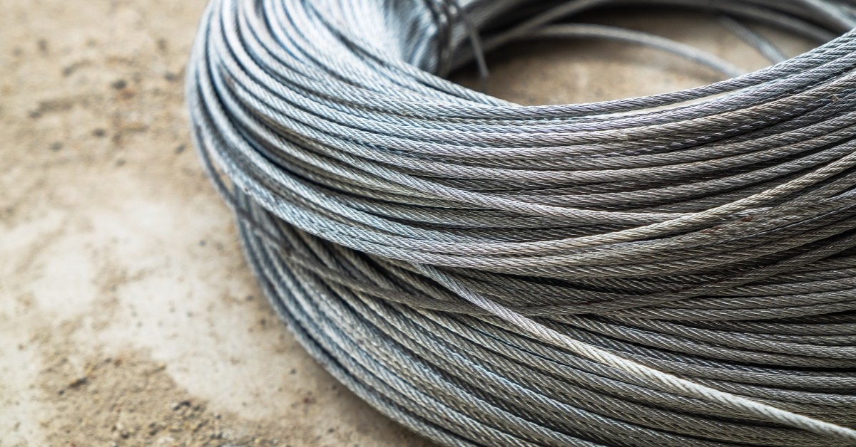
Wire rope is a complex mechanical device that has many moving parts all working in tandem to help support and move an object or load. In the lifting and rigging industries, wire rope is attached to a crane or hoist and fitted with swivels, shackles or hooks to attach to a load and move it in a controlled matter. It can also be used to lift and lower elevators, or as a means of support for suspension bridges or towers.
Wire rope is a preferred lifting device for many reasons. Its unique design consists of multiple steel wires that form individual strands laid in a helical pattern around a core. This structure provides strength, flexibility, and the ability to handle bending stresses. Different configurations of the material, wire, and strand structure will provide different benefits for the specific lifting application, including:Strength
However, selecting the proper wire rope for your lifting application requires some careful thought. Our goal is to help you understand the components of a wire rope, the construction of wire rope, and the different types of wire rope and what they might be used for. This will allow you to select the best performing and longest-lasting wire rope for the job at hand.
A wire rope is, in reality, a very complicated machine. A typical 6 x 25 rope has 150 wires in its outer strands, all of which move independently and together in a very complicated pattern around the core as the rope bends. Clearances between wires and strands are balanced when a rope is designed so that proper bearing clearances will exist to permit internal movement and adjustment of wires and strands when the rope has to bend. These clearances will vary as bending occurs, but are of the same range as the clearances found in automobile engine bearings.
Understanding and accepting the “machine idea” gives a rope user a greater respect for rope, and enables them to obtain better performance and longer useful life from rope applications. Anyone who uses a rope can use it more efficiently and effectively when they fully understand the machine concept.
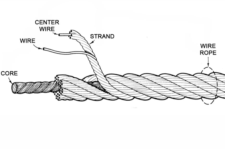
Wires are the smallest component of wire rope and they make up the individual strands in the rope. Wires can be made from a variety of metal materials including steel, iron, stainless steel, monel, and bronze. The wires can be manufactured in a variety of grades that relate to the strength, resistance to wear, fatigue resistance, corrosion resistance, and curve of the wire rope.
Strands of wire rope consist of two or more wires arranged and twisted in a specific arrangement. The individual strands are then laid in a helical pattern around the core of the rope.
The core of a wire rope runs through the center of the rope and supports the strands and helps to maintain their relative position under loading and bending stresses. Cores can be made from a number of different materials including natural or synthetic fibers and steel.
Lubrication is applied during the manufacturing process and penetrates all the way to the core. Wire rope lubrication has two primary benefits:Reduces friction as the individual wires and strands move over each other
The number of layers of wires, the number of wires per layer, and the size of the wires per layer all affect the strand pattern type. Wire rope can be constructed using one of the following patterns, or can be constructed using two or more of the patterns below.Single Layer – The most common example is a 7 wire strand with a single-wire center and six wires of the same diameter around it.
Filler Wire – Two layers of uniform-size wire around a center with the inner layer having half the number of wires as the outer layer. Small filler wires, equal to the number in the inner layer, are laid in valleys of the inner wire.
Seale – Two layers of wires around a center with the same number of wires in each layer. All wires in each layer are the same diameter. The large outer wires rest in the valleys between the smaller inner wires.
Warrington – Two layers of wires around a center with one diameter of wire in the inner layer, and two diameters of wire alternating large and small in the outer later. The larger outer-layer wires rest in the valleys, and the smaller ones on the crowns of the inner layer.
On a preformed wire rope, the strands and wires are formed during the manufacturing process to the helical shape that they will take in a finished wire rope.
Preformed rope can be advantageous in certain applications where it needs to spool more uniformly on a drum, needs greater flexibility, or requires more fatigue-resistance when bending.
Direction and type of lay refer to the way the wires are laid to form a strand (either right or left) and how the strands are laid around the core (regular lay, lang lay, or alternate lay).Regular Lay – The wires line up with the axis of the rope. The direction of the wire lay in the strand is opposite to the direction of the strand lay. Regular lay ropes are more resistant to crushing forces, are more naturally rotation-resistant, and also spool better in a drum than lang lay ropes.
Lang Lay– The wires form an angle with the axis of the rope. The wire lay and strand lay around the core in the same direction. Lang Lay ropes have a greater fatigue-resistance and are more resistant to abrasion.
A steel core can be an independent wire rope or an individual strand. Steel cores are best suited for applications where a fiber core may not provide adequate support, or in an operating environment where temperatures could exceed 180° F.
The classifications of wire rope provide the total number of strands, as well as a nominal or exact number of wires in each strand. These are general classifications and may or may not reflect the actual construction of the strands. However, all wire ropes of the same size and wire grade in each classification will have the SAME strength and weight ratings and usually the same pricing.
Besides the general classifications of wire rope, there are other types of wire rope that are special construction and designed for special lifting applications.
Some types of wire rope, especially lang lay wire rope, are more susceptible to rotation when under load. Rotation resistant wire rope is designed to resist twisting, spinning, or rotating and can be used in a single line or multi-part system.
Special care must be taken when handling, unreeling, and installing rotation resistant wire rope. Improper handling or spooling can introduce twist into the rope which can cause uncontrolled rotation.
Compacted strand wire rope is manufactured using strands that have been compacted, reducing the outer diameter of the entire strand, by means of passing through a die or rollers. This process occurs prior to closing of the rope.
This process flattens the surface of the outer wires in the strand, but also increases the density of the strand. This results in a smoother outer surface and increases the strength compared to comparable round wire rope (comparing same diameter and classification), while also helping to extend the surface life due to increased wear resistance.
A swaged wire rope differs from a compacted strand wire rope, in that a swaged wire rope’s diameter is compacted, or reduced, by a rotary swager machine after the wire rope has been closed. A swaged wire rope can be manufactured using round or compacted strands.
The advantages of a swaged wire rope are that they are more resistant to wear, have better crushing resistance, and high strength compared to a round strand wire rope of equal diameter and classification. However, a swaged wire rope may have less bending fatigue resistance.
A plastic coating can be applied to the exterior surface of a wire rope to provide protection against abrasion, wear, and other environmental factors that may cause corrosion. However, because you can’t see the individual strands and wires underneath the plastic coating, they can be difficult to inspect.
Plastic filled wire ropes are impregnated with a matrix of plastic where the internal spaces between the strands and wires are filled. Plastic filling helps to improve bending fatigue by reducing the wear internally and externally. Plastic filled wire ropes are used for demanding lifting applications.
This type of wire rope uses an Independent Wire Rope Core (IWRC) that is either filled with plastic or coated in plastic to reduce internal wear and increase bending fatigue life.
Remember, wire rope is a complex piece of mechanical machinery. There are a number of different specifications and properties that can affect the performance and service life of wire rope. Consider the following when specifying the best type of wire rope for your lifting application:Strength
When you select a piece of rope that is resistant to one property, you will most likely have a trade-off that affects another property. For example, a fiber core rope will be more flexible, but may have less crushing resistance. A rope with larger diameter wires will be more abrasion resistant, but will offer less fatigue resistance.
At Mazzella Companies, we offer all different kinds of wire rope from all of the leading manufacturers. We sell the highest-quality domestic and non-domestic rigging products because product quality and operating safety go hand-in-hand. We have one of the largest and most complete inventories of both domestic and non-domestic rigging and lifting products to suit your lifting needs.
If you’re looking for a standard or custom specified wire rope for your lifting project, contact a Lifting Specialist at a Mazzella Companies location near you.
We stock well over 2,000,000 feet of wire rope in our various locations … ready for immediate delivery! We provide wire rope assemblies, and manufacture bridge cables, crane cables, steel mill cables, and thousands of OEM assemblies.
In stricter senses, the term wire rope refers to a diameter larger than 9.5 mm (3⁄8 in), with smaller gauges designated cable or cords.wrought iron wires were used, but today steel is the main material used for wire ropes.
Historically, wire rope evolved from wrought iron chains, which had a record of mechanical failure. While flaws in chain links or solid steel bars can lead to catastrophic failure, flaws in the wires making up a steel cable are less critical as the other wires easily take up the load. While friction between the individual wires and strands causes wear over the life of the rope, it also helps to compensate for minor failures in the short run.
Wire ropes were developed starting with mining hoist applications in the 1830s. Wire ropes are used dynamically for lifting and hoisting in cranes and elevators, and for transmission of mechanical power. Wire rope is also used to transmit force in mechanisms, such as a Bowden cable or the control surfaces of an airplane connected to levers and pedals in the cockpit. Only aircraft cables have WSC (wire strand core). Also, aircraft cables are available in smaller diameters than wire rope. For example, aircraft cables are available in 1.2 mm (3⁄64 in) diameter while most wire ropes begin at a 6.4 mm (1⁄4 in) diameter.suspension bridges or as guy wires to support towers. An aerial tramway relies on wire rope to support and move cargo overhead.
Modern wire rope was invented by the German mining engineer Wilhelm Albert in the years between 1831 and 1834 for use in mining in the Harz Mountains in Clausthal, Lower Saxony, Germany.chains, such as had been used before.
Wilhelm Albert"s first ropes consisted of three strands consisting of four wires each. In 1840, Scotsman Robert Stirling Newall improved the process further.John A. Roebling, starting in 1841suspension bridge building. Roebling introduced a number of innovations in the design, materials and manufacture of wire rope. Ever with an ear to technology developments in mining and railroading, Josiah White and Erskine Hazard, principal ownersLehigh Coal & Navigation Company (LC&N Co.) — as they had with the first blast furnaces in the Lehigh Valley — built a Wire Rope factory in Mauch Chunk,Pennsylvania in 1848, which provided lift cables for the Ashley Planes project, then the back track planes of the Summit Hill & Mauch Chunk Railroad, improving its attractiveness as a premier tourism destination, and vastly improving the throughput of the coal capacity since return of cars dropped from nearly four hours to less than 20 minutes. The decades were witness to a burgeoning increase in deep shaft mining in both Europe and North America as surface mineral deposits were exhausted and miners had to chase layers along inclined layers. The era was early in railroad development and steam engines lacked sufficient tractive effort to climb steep slopes, so incline plane railways were common. This pushed development of cable hoists rapidly in the United States as surface deposits in the Anthracite Coal Region north and south dove deeper every year, and even the rich deposits in the Panther Creek Valley required LC&N Co. to drive their first shafts into lower slopes beginning Lansford and its Schuylkill County twin-town Coaldale.
The German engineering firm of Adolf Bleichert & Co. was founded in 1874 and began to build bicable aerial tramways for mining in the Ruhr Valley. With important patents, and dozens of working systems in Europe, Bleichert dominated the global industry, later licensing its designs and manufacturing techniques to Trenton Iron Works, New Jersey, USA which built systems across America. Adolf Bleichert & Co. went on to build hundreds of aerial tramways around the world: from Alaska to Argentina, Australia and Spitsbergen. The Bleichert company also built hundreds of aerial tramways for both the Imperial German Army and the Wehrmacht.
In the last half of the 19th century, wire rope systems were used as a means of transmitting mechanical powercable cars. Wire rope systems cost one-tenth as much and had lower friction losses than line shafts. Because of these advantages, wire rope systems were used to transmit power for a distance of a few miles or kilometers.
Steel wires for wire ropes are normally made of non-alloy carbon steel with a carbon content of 0.4 to 0.95%. The very high strength of the rope wires enables wire ropes to support large tensile forces and to run over sheaves with relatively small diameters.
In the mostly used parallel lay strands, the lay length of all the wire layers is equal and the wires of any two superimposed layers are parallel, resulting in linear contact. The wire of the outer layer is supported by two wires of the inner layer. These wires are neighbors along the whole length of the strand. Parallel lay strands are made in one operation. The endurance of wire ropes with this kind of strand is always much greater than of those (seldom used) with cross lay strands. Parallel lay strands with two wire layers have the construction Filler, Seale or Warrington.
In principle, spiral ropes are round strands as they have an assembly of layers of wires laid helically over a centre with at least one layer of wires being laid in the opposite direction to that of the outer layer. Spiral ropes can be dimensioned in such a way that they are non-rotating which means that under tension the rope torque is nearly zero. The open spiral rope consists only of round wires. The half-locked coil rope and the full-locked coil rope always have a centre made of round wires. The locked coil ropes have one or more outer layers of profile wires. They have the advantage that their construction prevents the penetration of dirt and water to a greater extent and it also protects them from loss of lubricant. In addition, they have one further very important advantage as the ends of a broken outer wire cannot leave the rope if it has the proper dimensions.
Stranded ropes are an assembly of several strands laid helically in one or more layers around a core. This core can be one of three types. The first is a fiber core, made up of synthetic material or natural fibers like sisal. Synthetic fibers are stronger and more uniform but cannot absorb much lubricant. Natural fibers can absorb up to 15% of their weight in lubricant and so protect the inner wires much better from corrosion than synthetic fibers do. Fiber cores are the most flexible and elastic, but have the downside of getting crushed easily. The second type, wire strand core, is made up of one additional strand of wire, and is typically used for suspension. The third type is independent wire rope core (IWRC), which is the most durable in all types of environments.ordinary lay rope if the lay direction of the wires in the outer strands is in the opposite direction to the lay of the outer strands themselves. If both the wires in the outer strands and the outer strands themselves have the same lay direction, the rope is called a lang lay rope (from Dutch langslag contrary to kruisslag,Regular lay means the individual wires were wrapped around the centers in one direction and the strands were wrapped around the core in the opposite direction.
Multi-strand ropes are all more or less resistant to rotation and have at least two layers of strands laid helically around a centre. The direction of the outer strands is opposite to that of the underlying strand layers. Ropes with three strand layers can be nearly non-rotating. Ropes with two strand layers are mostly only low-rotating.
Stationary ropes, stay ropes (spiral ropes, mostly full-locked) have to carry tensile forces and are therefore mainly loaded by static and fluctuating tensile stresses. Ropes used for suspension are often called cables.
Track ropes (full locked ropes) have to act as rails for the rollers of cabins or other loads in aerial ropeways and cable cranes. In contrast to running ropes, track ropes do not take on the curvature of the rollers. Under the roller force, a so-called free bending radius of the rope occurs. This radius increases (and the bending stresses decrease) with the tensile force and decreases with the roller force.
Wire rope slings (stranded ropes) are used to harness various kinds of goods. These slings are stressed by the tensile forces but first of all by bending stresses when bent over the more or less sharp edges of the goods.
Technical regulations apply to the design of rope drives for cranes, elevators, rope ways and mining installations. Factors that are considered in design include:
Donandt force (yielding tensile force for a given bending diameter ratio D/d) - strict limit. The nominal rope tensile force S must be smaller than the Donandt force SD1.
The wire ropes are stressed by fluctuating forces, by wear, by corrosion and in seldom cases by extreme forces. The rope life is finite and the safety is only ensured by inspection for the detection of wire breaks on a reference rope length, of cross-section loss, as well as other failures so that the wire rope can be replaced before a dangerous situation occurs. Installations should be designed to facilitate the inspection of the wire ropes.
Lifting installations for passenger transportation require that a combination of several methods should be used to prevent a car from plunging downwards. Elevators must have redundant bearing ropes and a safety gear. Ropeways and mine hoistings must be permanently supervised by a responsible manager and the rope must be inspected by a magnetic method capable of detecting inner wire breaks.
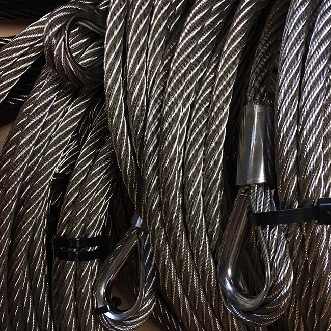
The end of a wire rope tends to fray readily, and cannot be easily connected to plant and equipment. There are different ways of securing the ends of wire ropes to prevent fraying. The common and useful type of end fitting for a wire rope is to turn the end back to form a loop. The loose end is then fixed back on the wire rope. Termination efficiencies vary from about 70% for a Flemish eye alone; to nearly 90% for a Flemish eye and splice; to 100% for potted ends and swagings.
When the wire rope is terminated with a loop, there is a risk that it will bend too tightly, especially when the loop is connected to a device that concentrates the load on a relatively small area. A thimble can be installed inside the loop to preserve the natural shape of the loop, and protect the cable from pinching and abrading on the inside of the loop. The use of thimbles in loops is industry best practice. The thimble prevents the load from coming into direct contact with the wires.
A wire rope clip, sometimes called a clamp, is used to fix the loose end of the loop back to the wire rope. It usually consists of a U-bolt, a forged saddle, and two nuts. The two layers of wire rope are placed in the U-bolt. The saddle is then fitted to the bolt over the ropes (the saddle includes two holes to fit to the U-bolt). The nuts secure the arrangement in place. Two or more clips are usually used to terminate a wire rope depending on the diameter. As many as eight may be needed for a 2 in (50.8 mm) diameter rope.
The mnemonic "never saddle a dead horse" means that when installing clips, the saddle portion of the assembly is placed on the load-bearing or "live" side, not on the non-load-bearing or "dead" side of the cable. This is to protect the live or stress-bearing end of the rope against crushing and abuse. The flat bearing seat and extended prongs of the body are designed to protect the rope and are always placed against the live end.
An eye splice may be used to terminate the loose end of a wire rope when forming a loop. The strands of the end of a wire rope are unwound a certain distance, then bent around so that the end of the unwrapped length forms an eye. The unwrapped strands are then plaited back into the wire rope, forming the loop, or an eye, called an eye splice.
A Flemish eye, or Dutch Splice, involves unwrapping three strands (the strands need to be next to each other, not alternates) of the wire and keeping them off to one side. The remaining strands are bent around, until the end of the wire meets the "V" where the unwrapping finished, to form the eye. The strands kept to one side are now re-wrapped by wrapping from the end of the wire back to the "V" of the eye. These strands are effectively rewrapped along the wire in the opposite direction to their original lay. When this type of rope splice is used specifically on wire rope, it is called a "Molly Hogan", and, by some, a "Dutch" eye instead of a "Flemish" eye.
Swaging is a method of wire rope termination that refers to the installation technique. The purpose of swaging wire rope fittings is to connect two wire rope ends together, or to otherwise terminate one end of wire rope to something else. A mechanical or hydraulic swager is used to compress and deform the fitting, creating a permanent connection. Threaded studs, ferrules, sockets, and sleeves are examples of different swaged terminations.
A wedge socket termination is useful when the fitting needs to be replaced frequently. For example, if the end of a wire rope is in a high-wear region, the rope may be periodically trimmed, requiring the termination hardware to be removed and reapplied. An example of this is on the ends of the drag ropes on a dragline. The end loop of the wire rope enters a tapered opening in the socket, wrapped around a separate component called the wedge. The arrangement is knocked in place, and load gradually eased onto the rope. As the load increases on the wire rope, the wedge become more secure, gripping the rope tighter.
Poured sockets are used to make a high strength, permanent termination; they are created by inserting the wire rope into the narrow end of a conical cavity which is oriented in-line with the intended direction of strain. The individual wires are splayed out inside the cone or "capel", and the cone is then filled with molten lead-antimony-tin (Pb80Sb15Sn5) solder or "white metal capping",zincpolyester resin compound.
Donald Sayenga. "Modern History of Wire Rope". History of the Atlantic Cable & Submarine Telegraphy (atlantic-cable.com). Archived from the original on 3 February 2014. Retrieved 9 April 2014.

Any wire rope in use should be inspected on a regular basis. You have too much at stake in lives and equipment to ignore thorough examination of the rope at prescribed intervals.
The purpose of inspection is to accurately estimate the service life and strength remaining in a rope so that maximum service can be had within the limits of safety. Results of the inspection should be recorded to provide a history of rope performance on a particular job.
On most jobs wire rope must be replaced before there is any risk of failure. A rope broken in service can destroy machinery and curtail production. It can also kill.
Because of the great responsibility involved in ensuring safe rigging on equipment, the person assigned to inspect should know wire rope and its operation thoroughly. Inspections should be made periodically and before each use, and the results recorded.
When inspecting the rope, the condition of the drum, sheaves, guards, cable clamps and other end fittings should be noted. The condition of these parts affects rope wear: any defects detected should be repaired.
To ensure rope soundness between inspections, all workers should participate. The operator can be most helpful by watching the ropes under his control. If any accident involving the ropes occurs, the operator should immediately shut down his equipment and report the accident to his supervisor. The equipment should be inspected before resuming operation.
The Occupational Safety and Health Act has made periodic inspection mandatory for most wire rope applications. If you need help locating the regulations that apply to your application, please give our rigging experts a call.
Copyright © 2022 by Society of Corporate Compliance and Ethics (SCCE) & Health Care Compliance Association (HCCA). No claim to original US Government works. All rights reserved. All information provided through this site, including without limitation all information such as the “look and feel” of the site, data files, graphics, text, photographs, drawings, logos, images, sounds, music, video or audio files on this site, is owned and/or licensed by SCCE & HCCA or its suppliers and is subject to United States and international copyright, trademark and other intellectual property laws. Any third party logos and/or content provided herein is owned by such third parties and is used by permission herein. Your use of this site to is subject to our Terms Of Use and Privacy Statement.
Wire rope must be inspected as part of the shift, monthly, and annual inspections required by. The shift and monthly inspections must evaluate all rope that is visible during the shift in which the inspection is conducted. The annual inspection must include the entire length of the rope. The shift and monthly inspections must pay particular attention to the following:
You must take certain action if an inspection reveals a defect in the rope. Some defects require either that the rope be removed from service or the damaged section be severed. For others, the inspector must evaluate whether the defect constitutes a safety hazard, with the corrective action depending on the outcome of the evaluation. Note that, if a wire rope must be repaired or replaced, either the equipment (as a whole) or the hoist with that wire rope must be tagged-out during the repair/replacement process.
Where severing the rope is permitted, the section that is damaged must be discarded. Two undamaged sections may not be spliced to make a longer rope. If the undamaged part that remains is too short for the drum to have two full wraps of rope when the load and/or boom is in its lowest position, the rope cannot be used and must be replaced.
Wire rope that has made electrical contact with a power line (either by the rope, the equipment, or the load contacting the line) must be immediately removed from service even if no damage is visible. The rope may have suffered internal damage that cannot be repaired.
In running wire ropes: six randomly distributed broken wires in one rope lay, or three broken wires in one strand in one rope lay, where a rope lay is the length along the rope in which one strand makes a complete revolution around the rope
In rotation resistant ropes: two randomly distributed broken wires in six rope diameters, or four randomly distributed broken wires in 30 rope diameters
In pendants or standing wire ropes: more than two broken wires in one rope lay located in rope beyond end connections, or more than one broken wire in a rope lay located at an end connection
Exception:If the wire rope manufacturer has approved different criteria for visible broken wires or diameter reduction, you may follow those criteria instead of those above.
Significant distortion of the wire rope structure such as kinking, crushing, unstranding, birdcaging, signs of core failure, or steel core protrusion between the outer strands
If they are not found to be an immediate hazard:You may continue to use the rope. However, if such a defect is identified during an annual inspection, you must check it during each monthly inspection. Note that this may require a more complete monthly inspection than would otherwise be required because the annual inspection must cover the entire rope and may reveal a defect in a part of the rope that would not normally be visible during a shift or monthly inspection.

To create cables for rigging equipment, cable and wire rope manufacturers begin with long strips of high tensile metal and weave them together tightly into strands. Once these strands are created, these are also tightly spun together to form a helix type pattern. This type of cable structure enhances the reliability, durability, and strength of the cable.
Cable on a ship that is used as part of the rigging is referred to as "cordage," and there are several different types of cordage. Cordage in a fixed position is referred to as standing rigging, which is usually installed between the mast and the deck to add tension and to hold the mast firmly in place. Running rigging is the cordage that is used to control the movement of the sails. In order to move smoothly over pulleys, this type of rigging has to be flexible but also has to endure the strain from high winds, holding the sails in place.
Historically, heavy ropes were used for rigging on large marine vessels due to technological limitations. With the industrialization of the world and technological advancement, metal cable rigging quickly took the place of fiber ropes, since fiber ropes are far more susceptible to wearing and breaking. Exposure to the sun and friction has a much more devastating effect on fiber ropes than cable rigging, which means they have to be replaced more often or risk them causing a potentially dangerous situation.
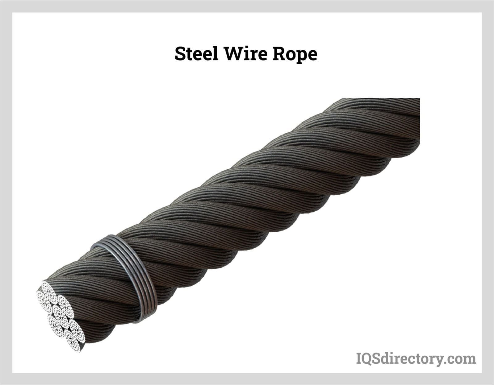
Wire rope forms an important part of many machines and structures. It is comprised of continuous wire strands wound around a central core. There are many kinds of wire rope designed for different applications. Most of them are steel wires made into strands wound with each other. The core can be made of steel, rope or even plastics.
Wire ropes (cables) are identified by several parameters including size, grade of steel used, whether or not it is preformed, by its lay, the number of strands and the number of wires in each strand.
A typical strand and wire designation is 6x19. This denotes a rope made up of six strands with 19 wires in each strand. Different strand sizes and arrangements allow for varying degrees of rope flexibility and resistance to crushing and abrasion. Small wires are better suited to being bent sharply over small sheaves (pulleys). Large outer wires are preferred when the cable will be rubbed or dragged through abrasives.
There are three types of cores. An independent wire rope core (IWRC) is normally a 6x7 wire rope with a 1x7 wire strand core resulting in a 7x7 wire rope. IWRCs have a higher tensile and bending breaking strength than a fiber core rope and a high resistance to crushing and deformation.
A wire strand core (WSC) rope has a single wire strand as its core instead of a multistrand wire rope core. WSC ropes are high strength and are mostly used as static or standing ropes.
Wire ropes also have fiber cores. Fiber core ropes were traditionally made with sisal rope, but may also use plastic materials. The fiber core ropes have less strength than steel core ropes. Fiber core ropes are quite flexible and are used in many overhead crane applications.
The lay of a wire rope is the direction that the wire strands and the strands in the cable twist. There are four common lays: right lay, left lay, regular lay and lang lay. In a right lay rope the strands twist to the right as it winds away from the observer. A left lay twists to the left. A regular lay rope has the wires in the strands twisted in the opposite direction from the strands of the cable. In a lang lay rope, the twist of the strands and the wires in the strands are both twisted the same way. Lang lay ropes are said to have better fatigue resistance due to the flatter exposure of the wires.
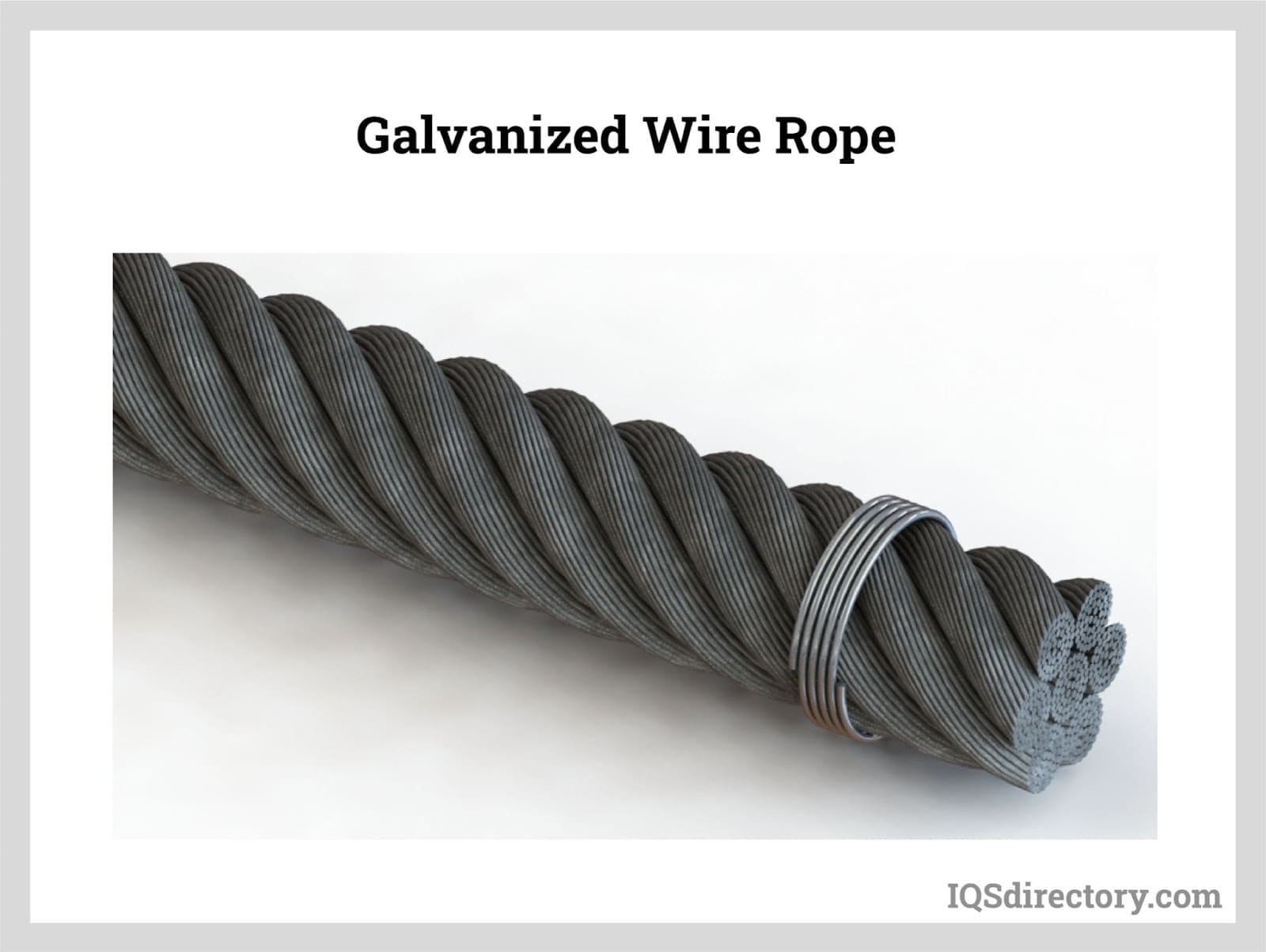
Wire ropes are made mostly from high carbon steel for strength, versatility, resilience and availability and for cost consideration. Wire ropes can be uncoated or galvanized. Several grades of steel are used and are described in Table 1.
Steel cable wire is stiff and springy. In nonpreformed rope construction, broken or cut wires will straighten and stick out of the rope as a burr, posing a safety hazard. A preformed cable is made of wires that are shaped so that they lie naturally in their position in the strand, preventing the wires from protruding and potentially causing injury. Preformed wire ropes also have better fatigue resistance than nonpreformed ropes and are ideal for working over small sheaves and around sharp angles.
Lubricating wire ropes is a difficult proposition, regardless of the construction and composition. Ropes with fiber cores are somewhat easier to lubricate than those made exclusively from steel materials. For this reason, it is important to carefully consider the issue of field relubrication when selecting rope for an application.
There are two types of wire rope lubricants, penetrating and coating. Penetrating lubricants contain a petroleum solvent that carries the lubricant into the core of the wire rope then evaporates, leaving behind a heavy lubricating film to protect and lubricate each strand (Figure 2). Coating lubricants penetrate slightly, sealing the outside of the cable from moisture and reducing wear and fretting corrosion from contact with external bodies.
Both types of wire rope lubricants are used. But because most wire ropes fail from the inside, it is important to make sure that the center core receives sufficient lubricant. A combination approach in which a penetrating lubricant is used to saturate the core, followed with a coating to seal and protect the outer surface, is recommended. Wire rope lubricants can be petrolatum, asphaltic, grease, petroleum oils or vegetable oil-based (Figure 3).
Petrolatum compounds, with the proper additives, provide excellent corrosion and water resistance. In addition, petrolatum compounds are translucent, allowing the technician to perform visible inspection. Petrolatum lubricants can drip off at higher temperatures but maintain their consistency well under cold temperature conditions.
Various types of greases are used for wire rope lubrication. These are the coating types that penetrate partially but usually do not saturate the rope core. Common grease thickeners include sodium, lithium, lithium complex and aluminum complex soaps. Greases used for this application generally have a soft semifluid consistency. They coat and achieve partial penetration if applied with pressure lubricators.
Petroleum and vegetable oils penetrate best and are the easiest to apply because proper additive design of these penetrating types gives them excellent wear and corrosion resistance. The fluid property of oil type lubricants helps to wash the rope to remove abrasive external contaminants.
Wire ropes are lubricated during the manufacturing process. If the rope has a fiber core center, the fiber will be lubricated with a mineral oil or petrolatum type lubricant. The core will absorb the lubricant and function as a reservoir for prolonged lubrication while in service.
If the rope has a steel core, the lubricant (both oil and grease type) is pumped in a stream just ahead of the die that twists the wires into a strand. This allows complete coverage of all wires.
After the cable is put into service, relubrication is required due to loss of the original lubricant from loading, bending and stretching of the cable. The fiber core cables dry out over time due to heat from evaporation, and often absorb moisture. Field relubrication is necessary to minimize corrosion, protect and preserve the rope core and wires, and thus extend the service life of the wire rope.
If a cable is dirty or has accumulated layers of hardened lubricant or other contaminants, it must be cleaned with a wire brush and petroleum solvent, compressed air or steam cleaner before relubrication. The wire rope must then be dried and lubricated immediately to prevent rusting. Field lubricants can be applied by spray, brush, dip, drip or pressure boot. Lubricants are best applied at a drum or sheave where the rope strands have a tendency to separate slightly due to bending to facilitate maximum penetration to the core. If a pressure boot application is used, the lubricant is applied to the rope under slight tension in a straight condition. Excessive lubricant application should be avoided to prevent safety hazards.
Some key performance attributes to look for in a wire rope lubricant are wear resistance and corrosion prevention. Some useful performance benchmarks include high four-ball EP test values, such as a weld point (ASTM D2783) of above 350 kg and a load wear index of above 50. For corrosion protection, look for wire rope lubricants with salt spray (ASTM B117) resistance values above 60 hours and humidity cabinet (ASTM D1748) values of more than 60 days. Most manufacturers provide this type of data on product data sheets.
Cable life cycle and performance are influenced by several factors, including type of operation, care and environment. Cables can be damaged by worn sheaves, improper winding and splicing practices, and improper storage. High stress loading, shock loading, jerking heavy loads or rapid acceleration or deceleration (speed of the cable stopping and starting) will accelerate the wear rate.
Corrosion can cause shortened rope life due to metal loss, pitting and stress risers from pitting. If a machine is to be shut down for an extended period, the cables should be removed, cleaned, lubricated and properly stored. In service, corrosion and oxidation are caused by fumes, acids, salt brines, sulfur, gases, salt air, humidity and are accelerated by elevated temperatures. Proper and adequate lubricant application in the field can reduce corrosive attack of the cable.
Abrasive wear occurs on the inside and outside of wire ropes. Individual strands inside the rope move and rub against one another during normal operation, creating internal two-body abrasive wear. The outside of the cable accumulates dirt and contaminants from sheaves and drums. This causes three-body abrasive wear, which erodes the outer wires and strands. Abrasive wear usually reduces rope diameter and can result in core failure and internal wire breakage. Penetrating wire rope lubricants reduce abrasive wear inside the rope and also wash off the external surfaces to remove contaminants and dirt.
Many types of machines and structures use wire ropes, including draglines, cranes, elevators, shovels, drilling rigs, suspension bridges and cable-stayed towers. Each application has specific needs for the type and size of wire rope required. All wire ropes, regardless of the application, will perform at a higher level, last longer and provide greater user benefits when properly maintained.
Lubrication Engineers, Inc. has found through years of field experience, that longer wire rope life can be obtained through the use of penetrating lubricants, either alone or when used in conjunction with a coating lubricant. Practical experience at a South African mine suggests that life cycles may be doubled with this approach. At one mine site, the replacement rate for four 44-mm ropes was extended from an average 18.5 months to 43 months. At another mine, life cycles of four 43-mm x 2073 meter ropes were extended from an average 8 months to 12 months.
In another study involving 5-ton and 10-ton overhead cranes in the United States that used 3/8-inch and 5/8-inch diameter ropes, the average life of the ropes was doubled. The authors attribute this increased performance to the ability of the penetrating lubricant to displace water and contaminants while replacing them with oil, which reduces the wear and corrosion occurring throughout the rope. A good spray with penetrating wire rope lubricant effectively acts as an oil change for wire ropes.
In these examples, the savings in wire rope replacement costs (downtime, labor and capital costs) were substantial and dwarfed the cost of the lubricants. Companies who have realized the importance of proper wire rope lubrication have gained a huge advantage over those who purchase the lowest priced lubricant, or no lubricant at all, while replacing ropes on a much more frequent basis.


 8613371530291