
u bolt clips wire rope free sample

Meets or exceeds all requirements of ASME B30.26 including identification, ductility, design factor, proof load, and temperature requirements. Importantly, these wire rope clips meet other critical performance requirements including fatigue life, impact properties, and material traceability, not addressed by ASME B30.26.

GME Supply offers the best equipment for all of your steel and cable wire rope and guying needs. Browse our selection of cable, thimbles, u-bolt clips, ground anchors, and turnbuckles for great prices and fast shipping. We can help you with all of your wire rope and guying needs. Have questions or not finding the wire rope and guying supplies you’re looking for? Contact us today and one of our knowledgeable customer service representatives, and we"ll help you find a new way to "Climb Higher".

To calculate the overall star rating and percentage breakdown by star, we don’t use a simple average. Instead, our system considers things like how recent a review is and if the reviewer bought the item on Amazon. It also analyzed reviews to verify trustworthiness.
While these clips are not designed to be used in an overhead lifting situation (swage sleeves should be used instead), wire rope clips are heavy-duty wire rope clips that used for sustaining overhead loads. Examples include guy lines, support lines, scaffolding, etc.
U.S. Cargo Control offers two types of clips: standard (or U-Bolt) and fist-grip (or "double saddle"). Our line includes high-quality clips that work for any situation, including:
Install the first clip at the dead end side of the rope. The "U" side of the clip must always cover the dead end of the rope, and the "saddle" side of the clip on the live end of the rope. Place the nuts of the clip and tighten them using a torque wrench.
Next, apply the second clip and place it as close to the eye loop as possible. Same application for the clip. Tighten the nuts of the clip with a wrench. (If you"re planning on using more than two clips, do not tighten the nuts on the clip.)
Place more clips on the rope if you need more than two on the wire rope. Be sure to space them evenly between the end clips. Finally, tighten the end clips and apply tension to reach the recommended torque for the wire rope.
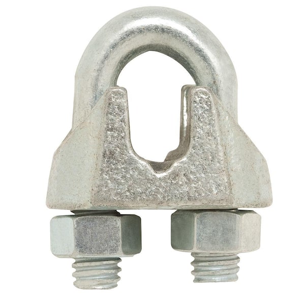
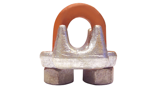
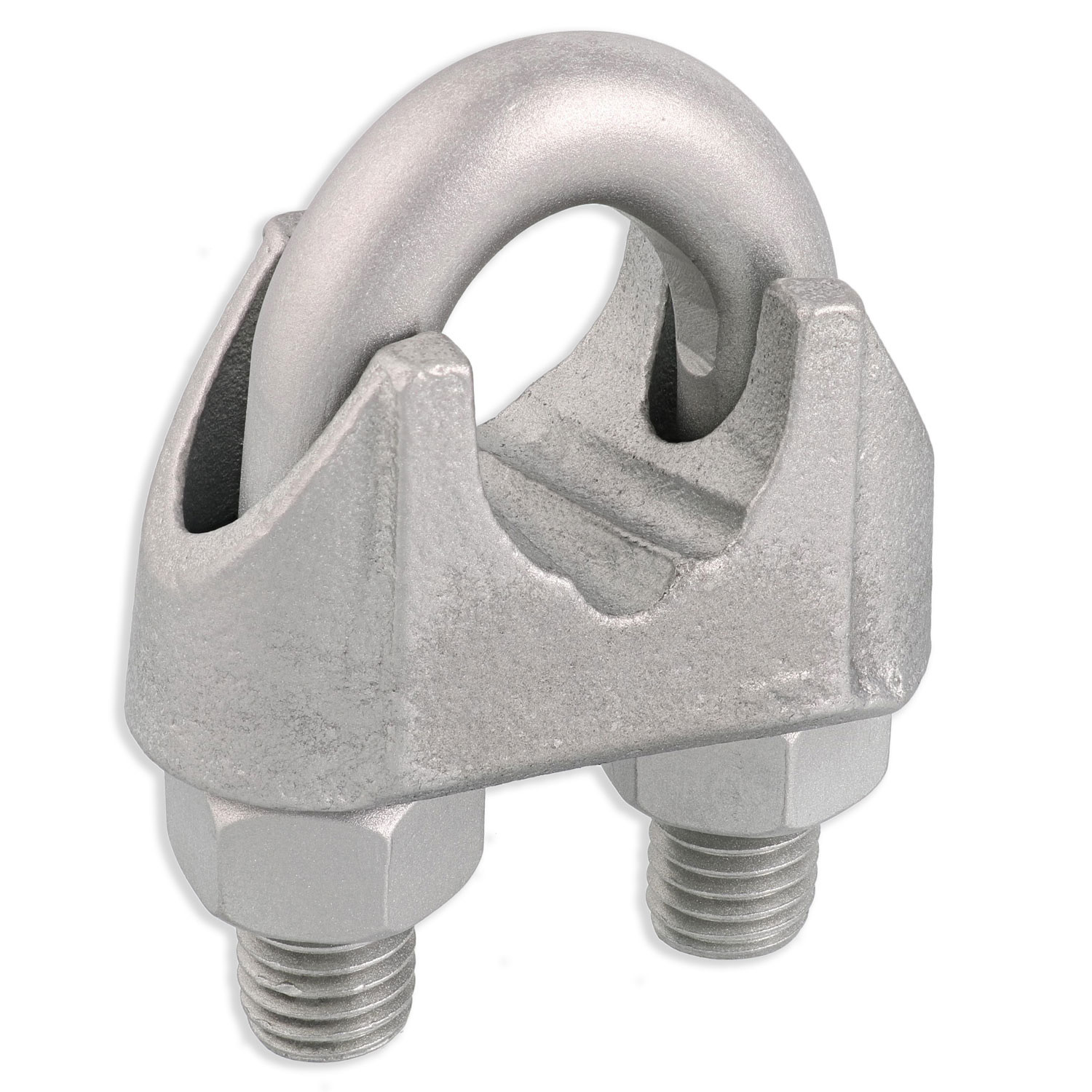
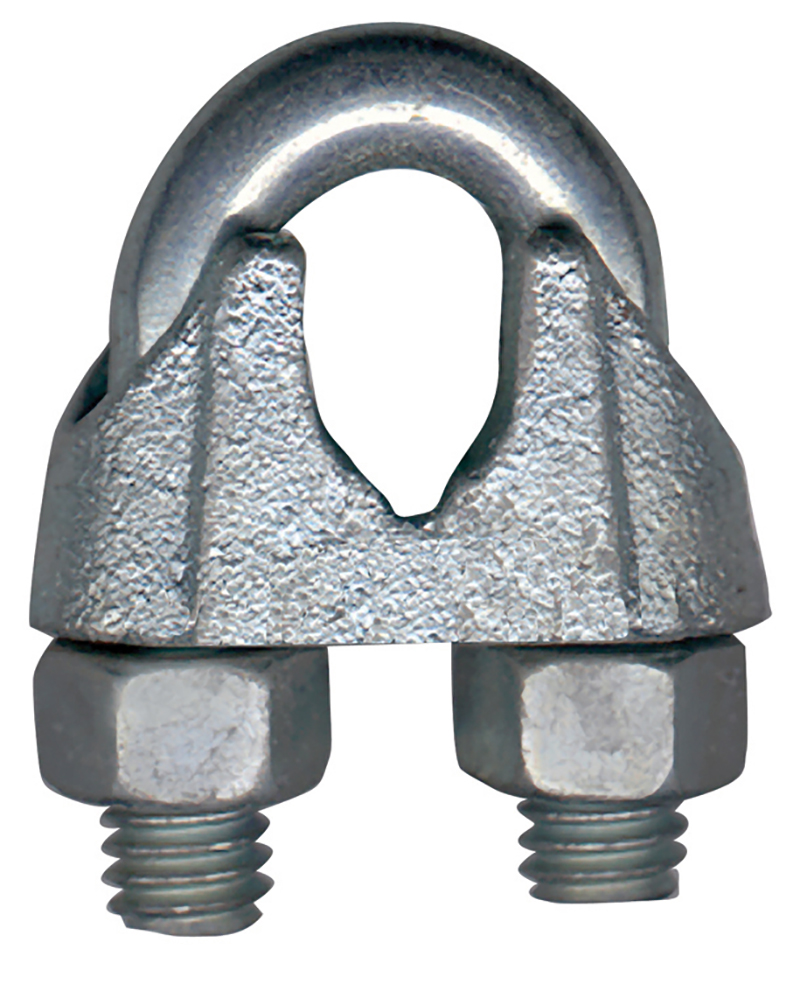
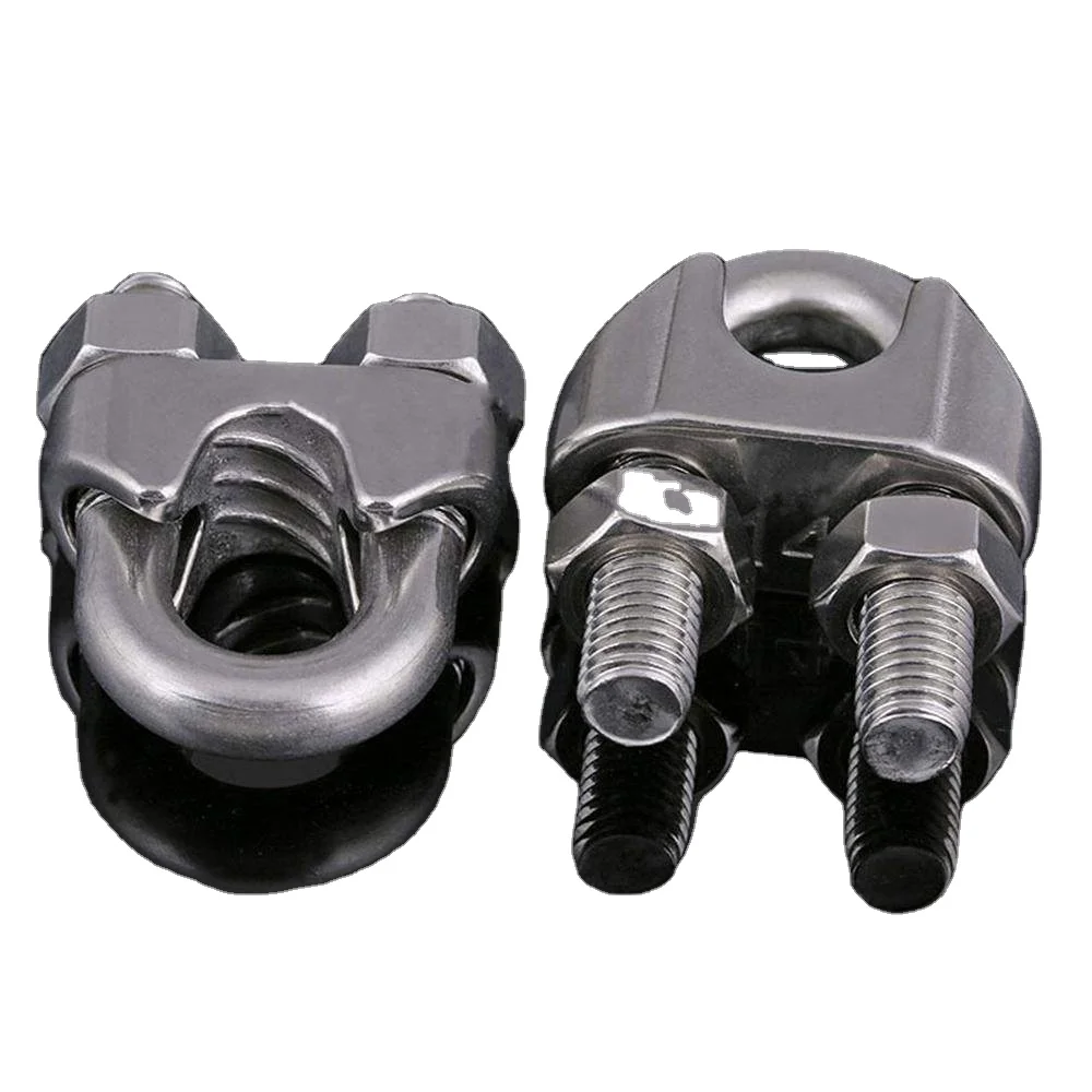
Wire rope clips, sometimes referred to as u bolt clamps, u bolt clips, u clips, u clamps or cable clamps, are used to secure the loose end of a wire rope when forming an eye. Wire rope u clips have a u-bolt that is secured into a saddle by two nuts. Wire rope assemblies almost always require two, or more wire rope clamps to secure the wire rope properly. When using wire rope cable clamps to form an eye in a wire rope, the working load limit of the wire rope is reduced by about 20%.
Here at Tri-State Rigging Equipment we pride ourselves on providing only the highest quality wire rope clamps from only the most reputable manufacturers. We can provide you with any wire rope clip on the market so, if you are unable to find what you are looking for, or if you don’t know exactly what you need, call or email our sales team to speak with a rigging product specialist.
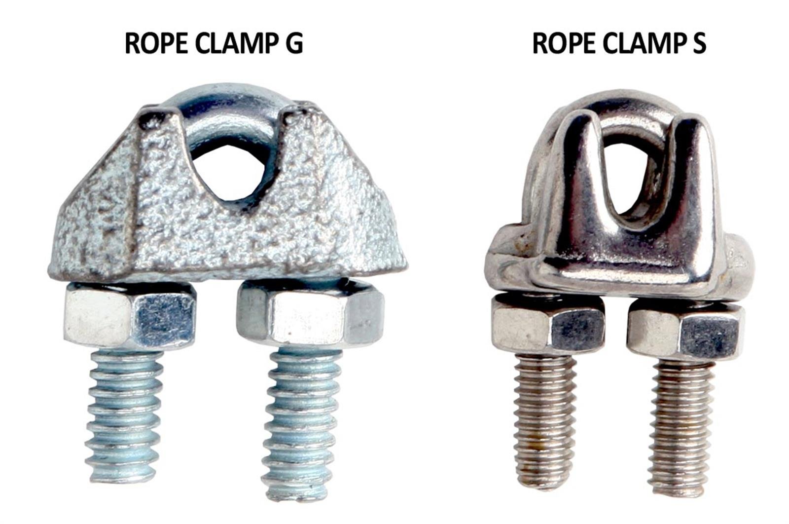
Wire rope cable clamps come in a variety of materials ranging from galvanized and zinc plated steel, to stainless steel. The two most important different types, however, are drop forged and malleable wire rope u bolt clips.
Drop forged wire rope clips are more heavy duty than malleable rope clips and can therefore be used for more heavy-duty rigging applications. In addition, they are galvanized with a heavy coating of zinc that resists the corrosion and abuse found in rugged work environments. Wire rope cable clamps of every type are not designed to be used in an overhead lift but drop forged wire rope u bolt clamps can be used to suspend an overhead load. This makes wire rope cable clamps ideal for use with:
Regarding the first question, if the load is being moved, wire rope clips are not to be used. If the load is being held in place, heavy-duty drop forged wire rope clips can be used. For the second question, if the load is near the ground, malleable wire rope clips may be used, as their lighter duty design is more than enough for the job. On the other hand, if the load is being suspended above the ground, heavier duty drop forged wire rope clamps must be used.
In the rigging and lifting industry there is a common saying that is used to remember the correct way to use wire rope u clips: “Never saddle a dead horse.” This means that the saddle of the u clamp should always be in contact with the live side of the wire rope rather than the dead side. The dead side of the wire rope is the side of the eye that has the cut end. The dead end is attached to the live end of the wire rope to form an eye and it is imperative that the saddle be on the live side of the wire rope.
Tri-State Rigging Equipment is a service provider and distributor for all wire rope cable clamps, and u bolt clips for rigging serving clients from coast to coast, Canada, Mexico and especially focused in the states of Missouri, Illinois, Indiana, Iowa, Kansas, Nebraska, Arkansas, Mississippi, Tennessee, Kentucky, South Carolina, Florida, and Oklahoma.
(a) Wire rope slings must be made from new or unused regular lay wire rope. The wire rope must be manufactured and tested in accordance with ASTM A 1023-02 and ASTM A 586.
(f) You must install and maintain wire rope clips, if used, in accordance with the recommendations of the clip manufacturer or a qualified person, or in accordance with the provisions of ASME B30.26-2010.
(g) You must not use slings made with wire rope clips as a choker hitch.Note:If using wire rope clips under these conditions, follow the guidance given in Table 15.
•Slings made of rope with 6x19 and 6x36 classification.A minimum clear length of rope 10 times the rope diameter between splices, sleeves, or end fittings (see Figure 15, Minimum Sling Length) unless approved by a qualified person.
•Braided slings.A minimum clear length of rope 40 times the component rope diameter between the loops or end fittings (see Figure 16, Minimum Braided Sling Length) unless approved by a qualified person.
•Grommets and endless slings.A minimum circumferential length of 96 times the body diameter of the grommet or endless sling unless approved by a qualified person.
(b) Rate slings with the load capacity of the lowest rated component of the sling. For example, if you use fittings that are rated lower than the sling material itself, identify the sling with the lower rated capacity.
(3) Identification information. All wire rope slings must have legible identification information attached to the sling which includes the information below, see sample tag in Figure 17. For slings in use that are manufactured before the effective date of this rule, you must add the information below before use or at the time the periodic inspection is completed.
Figure 17 Sample Wire Rope Sling ID TagNote:Sample tag for a 1/2" single-leg sling 6x19 or 6x36 classification, extra improved plow steel (EIPS) grade fiber core (FC) wire rope with a mechanical splice (ton = 2,000 lb).
(iii) You must not repair wire rope used in slings, you must replace wire rope. Only end attachments and fittings can be repaired on a wire rope sling.
(6) Proof load tests. Make sure the sling manufacturer or a qualified person proof load tests the following slings before initial use, according to Table 18:
(c) For single- or multiple-leg slings and endless slings, you must proof load each leg according to the requirements listed in Table 18 based on fabrication method. The proof load test must not exceed 50% of the component ropes" or structural strands" minimum breaking strength;
Note: For mechanical splice, swaged socket and poured socket slings follow the rope manufacturer"s recommendations for proof load testing provided that it is within the above-specified proof load range, including (c) of this subsection.
(a) You must use wire rope slings within the rated loads shown in Tables 7 through 15 in ASME B30.9-2010. For angles that are not shown in these tables, either use the rated load for the next lower angle or have a qualified person calculate the rated load.
(b) Prohibit the use of horizontal sling angles less than 30 degrees unless recommended by the sling manufacturer or a qualified person. See Figure 18.
(c) Rated loads for slings used in a choker hitch must conform to the values shown in the above referenced tables, provided that the angle of choke is 120 degrees or greater. See Figure 20 and Table 20, Angle of Choke.
(d) Use either Figure 20 and Table 20, the manufacturer, or a qualified person to determine the rated load if the angle of choke in a choker hitch is less than 120 degrees.
(iii) Keep a record of the most recent periodic inspection available, including the condition of the sling.Note:An external code mark on the sling is an acceptable means of recording the inspection as long as the code can be traced back to a record.
(g) Decrease the rated load of the sling when D/d ratios (Figure 19) smaller than 25 to one. Consult the sling manufacturer for specific data or refer to the Wire Rope Sling User"s Manual (wire rope technical board).
(i) You must protect slings in contact with edges, corners, or protrusions with a material of sufficient strength, thickness, and construction to prevent damage to the sling. See Figure 14.
Re: Wire rope clips on suspension scaffolds; safety latches on large crane hooks; hanging scaffolds - order of assembly; jobsite fabricated lifting accessories - criteria; and horizontal lifelines: use of wire rope clips, anchorages, number of persons allowed to be connected, requirements relating to sag, and use of synthetic rope.
This is in response to your facsimile dated November 14, 2003, to the Occupational Safety and Health Administration (OSHA). We have paraphrased your questions as follows:
Question 1(a) - (c): When using horizontal lifelines as part of personal fall arrest systems, what type of wire rope clips does OSHA require, and how many clips must be used? Additionally, what are the horizontal spacing criteria for the uprights?
Subpart M - Fall Protection, 29 CFR 1926.502, contains criteria requirements for fall protection systems. Horizontal lifelines may be used as part of a personal fall arrest system if provisions within §1926.502(d) are met. Section 1926.502(d)(8) requires that:
Horizontal lifelines shall be designed, installed, and used, under the supervision of a qualified person, as part of a complete personal fall arrest system, which maintains a safety factor of at least two.
Subpart M does not specify what type of wire rope clip or how many clips/clamps must be used when installing a horizontal lifeline. However, under §1926.502(d)(8), these decisions must be made under the supervision of a qualified person when the system is designed. The determination of the horizontal spacing criteria for uprights is also left to the qualified person"s supervisory approval.1
In an August 28, 2000 letter to Mr. Troxell2, we addressed the related issue of using wire rope clips on a wire rope guardrail. In that letter, we cautioned that, as a practical matter, it is unlikely that the criteria requirements for guardrails under §1926.502(b) could be met unless the manufacturer"s recommendations for the number of clips to be used on wire ropes of different diameters were followed (for example, the Crosby Group, Inc., general catalog 2000 edition, has tables showing their recommendations for their clips). We also pointed out that OSHA"s standard for rigging equipment used for material handling, 29 CFR 1926.251, has a table showing the number of clips required for wire rope ½-inch and greater. We noted that although that standard does not apply to wire rope used for guardrails, when designing a rope system to meet the §1926.502 guardrail requirements, following the tables at §1926.251 will normally ensure that there will be enough clips.
The forces exerted on a horizontal lifeline are substantially greater than those on a typical guardrail. Therefore, the system designer needs to ensure that the number, type, and location of clips will withstand the anticipated forces and meet the performance requirements in §1926.502 for horizontal lifelines.
The standard does not set a limit on the number of people that may be simultaneously attached to the same horizontal lifeline. Under §1926.502(d)(8), the determination of how many people may be simultaneously attached depends on a variety of factors that a qualified person must consider when designing the system.3
Extreme care should be taken in considering a horizontal lifeline for multiple tie-offs. The reason for this is that in multiple tie-offs to a horizontal lifeline, if one employee falls, the movement of the falling employee and the horizontal lifeline during arrest of the fall may cause other employees to fall also. Horizontal lifeline and anchorage strength should be increased for each additional employee to be tied-off. For these and other reasons, the design of systems using horizontal lifelines must only be done by qualified persons.
Although the possibility of one person falling may raise the risk of another person being pulled into a fall, it is not our position that the lifeline must necessarily be designed so that it can withstand a simultaneous fall by all the individuals tied-off to it. In assessing the total strength required for the lifeline, the qualified person must make a determination on the likelihood of simultaneous falls based on factors such as the type of walking/working surface the workers will be on, the length of their lanyards, and whether their work assignments call for them all to be near the edge at the same time.
Anchor points for a horizontal lifeline must be determined under the supervision of a qualified person under §1926.502(d)(8). Subpart M does not identify particular anchor points for horizontal lifelines. Appendix C, Section II (h)(1), provides some anchorage point considerations to be addressed when designing personal fall arrest systems.
Question 2: For a horizontal lifeline used as part of a personal fall arrest system during steel erection work, how tight should the lifeline be, and may synthetic rope be used for the horizontal lifeline?
Subpart R - Steel Erection, 29 CFR 1926.760, addresses fall protection requirements in steel erection. Section 1926.760(d), criteria for fall protection equipment, incorporates into Subpart M §1926.502(b)-(e), fall protection systems criteria and practices. Section 1926.502(d)(8) requires that:
Horizontal lifelines shall be designed, installed, and used, under the supervision of a qualified person, as part of a complete personal fall arrest system, which maintains a safety factor of at least two.
Therefore, a qualified person is required to determine how tight the lifeline should be based on site-specific factors. No other requirements are imposed by OSHA regarding the tightness of the lifeline, so long as it comports with a safety factor of at least two.
With regard to the use of synthetic ropes, §1926.502(d)(14) specifies that, when using non-wire rope, synthetic rope (rather than nature fiber rope) must be used:
Scaffolds shall be designed by a qualified person and shall be constructed and loaded in accordance with that design. Non-mandatory Appendix A to this subpart contains examples of criteria that will enable an employer to comply with paragraph (a). [Emphasis added.]
Qualified means one who, by possession of a recognized degree, certificate, or professional standing, or by extensive knowledge, training, and experience, has successfully demonstrated his/her ability to solve or resolve problems related to the subject matter, the work, or the project.
The employer is responsible for designing and assembling components in such a way that the completed system will meet the requirements of §1926.451(a). Scaffold components which are not selected and loaded in accordance with this Appendix, and components for which no specific guidelines or tables are given in this Appendix, must be designed and constructed in accordance with the capacity requirements of §1926.451(a).
The requirements set forth in §1926.451(b) must also be followed when erecting the scaffold. In regard to scaffold components used in the construction of the scaffold, §1926.451(b)(10) states:
Scaffold components manufactured by different manufacturers shall not be intermixed unless the components fit together without force and the scaffold"s structural integrity is maintained by the user. Scaffold components manufactured by different manufacturers shall not be modified in order to intermix them unless a competent person determines the resulting scaffold is structurally sound. [Emphasis added.]
Section 1926.451(f) sets out requirements involving the use of the scaffold. Where scaffolding is erected, moved, dismantled, or altered, §1926.451(f)(7) provides:
Scaffolds shall be erected, moved, dismantled, or altered only under the supervision and direction of a competent person qualified in scaffold erection, moving, dismantling, or alteration. Such activities shall be performed only by experienced and trained employees selected for such work by the competent person. [Emphasis added.]
Competent person means one who is capable of identifying existing and predictable hazards in the surroundings or working conditions which are unsanitary, hazardous, or dangerous to employees, and who has authorization to take prompt corrective measures to eliminate them.
When erecting the scaffold you describe, the employer must ensure that the scaffold has been designed by a qualified person and constructed and loaded in accordance with that design. If the designer requires the scaffold to be erected from the top down, then it must be erected in that manner. If the designer requires it to be erected from the bottom up, then that order must be followed. If the designer does not indicate one or the other order, then the competent person must determine whether the scaffold may be erected from the top down or the bottom up.
Question 4: Are there OSHA standards that specify criteria for constructing jobsite fabricated rigging equipment such as an equalizing beam, lifting beam, spreader beam, equalizing plates, tee lugs, lifting lugs, and welded scaffold brackets?
The only OSHA construction standards that contains specific criteria related to the construction of special custom design lifting accessories is 29 CFR 1926.251(a)(4), which states:
(4) Special custom design grabs, hooks, clamps, or other lifting accessories, for such units as modular panels, prefabricated structures and similar materials, shall be marked to indicate the safe working loads and shall be proof-tested prior to use to 125 percent of their rated load.
Question 5: Under §1926.451(d)(12)(v) and (vi), when wire rope clips are used on suspension scaffolds, "(v) U-bolt clips shall not be used at the point of suspension for any scaffold hoist," and "(vi) when U-bolt clips are used, the U-bolt shall be placed over the dead end of the rope, and the saddle shall be placed over the live end of the rope." Does §1926.451(d)(12)(v) contradict paragraph (d)(12)(vi)?
No. By its terms, §1926.451(d)(12)(v) prohibits the use of U-bolt clips at the point of suspension for any scaffold. The scaffold standard does not prohibit using U-bolt clips elsewhere. However, when using them elsewhere, under §1926.451(d)(12)(vi), the U-bolt must be placed over the dead end of the rope, and the saddle placed over the live end of the rope.
Question 6: Under §1926.251(c)(4)(iii), are eyes in wire rope bridles and slings or bull wires formed by wire rope clips permitted when used to lift scrap boxes or pendants?
This provision specifically prohibits eyes in wire rope bridles and slings or bull wires being formed by wire rope clips. There is no exception for lifting scrap boxes or pendants.
There are no OSHA standards setting criteria for horizontal high-lines. However, an employer"s use of a horizontal high-line must be in accordance with its obligations under Section 5(a)(1) of the Occupational Safety and Health Act (the "General Duty Clause"), which states:
Each employer shall furnish to each of his employees employment and a place of employment and a place of employment which are free from recognized hazards that are causing or are likely to cause death or serious physical harm to his employees.
In our view, the industry recognizes that the following engineering factors, among others, must be considered when designing horizontal high-lines: the span and sag of the wire rope line, the weight of the load being lifted, the initial tension of the rope line, and the size of the columns.
OSHA requirements for a safety latch on hooks do not depend of the size of the hook but rather the activity for which the hook is being used. Safety latches on hooks are required in two instances:
Hooks on overhaul ball assemblies, lower load blocks, or other attachment assemblies shall be of a type that can be closed and locked, eliminating the hook throat opening. Alternatively, an alloy anchor type shackle with a bolt, nut and retaining pin may be used.
Section 1926.753(d) prohibits workers engaged in steel erection activities from being directly under a suspended load, with some exceptions. Where those exceptions apply (i.e., where workers are engaged in the initial connection of steel or employees are unhooking the load), specific criteria apply. One such criterion is the requirement for safety latches.
This provision was intended to prevent the components from becoming accidentally unfastened from the hook and falling on the worker below. The preamble to the proposed rule explained that an "equivalent" device would include:
A hook with another type of closing device, i.e., a hook with a spring-loaded gate or another type of safety hook that would provide the same level of safety as a safety hook with a self-closing latch. (At 63 FR 43464, August 13, 1998.)
Neither the personnel platform nor the steel erection/working under load requirement has an exception for large hooks - the requirements apply irrespective of the size of the hook. Also, there is no "grandfather" exception for older hooks without safety latches.
Knotting wire rope compromises the integrity of the strength of the wire rope and is therefore prohibited. Based on the picture provided, which showed a knot in wire rope secured by a U-bolt clip, this practice would be in violation of §1926.251(c)(3).
Question 10: Do OSHA standards require the attachment of an orange and white flag to the highest point of a crane that is being used in the vicinity of an airport?
There are no OSHA standards that require the highest point of a crane to be marked to enhance visibility to air traffic. However, the use of a crane in the vicinity of an airport may be subject to requirements set by other regulatory agencies, such as the Federal Aviation Administration.
Question 11: Do OSHA standards specify a particular anchorage point for connecting the lanyards of workers on crane suspended personnel platforms? Do the standards limit the number of such workers that can be attached to an anchorage point?
This standard applies to the design [and]* * * use of personnel platforms on the load lines of cranes or derricks and the hoisting of personnel platforms on the load lines of cranes or derricks.
Except over water, employees occupying the personnel platform shall use a body belt/harness system with lanyard appropriately attached to the lower load block or overhaul ball, or to a structural member within the personnel platform capable of supporting a fall impact for employees using the anchorage. When working over water, the requirements of §1926.106 shall apply. [Emphasis added.]
Anchorages used for attachment of personal fall arrest equipment shall be independent of any anchorage being used to support or suspend platforms and capable of supporting at least 5,000 pounds * * * per employee attached or shall be designed, installed, and used as follows: (i) as part of a complete personal fall arrest system which maintains a safety factor of at least two; and (ii) under the supervision of a qualified person.
As you can see from the text of these provisions, §1926.550(g)(6)(vii) specifies the permissible locations of anchorage points - lower load block, overhaul ball, or the structural member within the personnel platform. Section 1926.502(d)(15) in Subpart M sets forth various criteria for anchorage points but does not establish a limit relative to the number of workers that can be attached to any one anchorage.
In addition, note that several other significant provisions in §1926.550(g) of Subpart N may affect the number of employees allowed in a personnel platform. These provisions include §1926.550(g)(4), which limits the number of employees on platforms to those required to do the work, and sets other requirements as well. Provisions most relevant to your question include §1926.550(g)(3)(i)(E) (limits total weight of loaded personnel platform and related rigging to 50 percent of rated capacity for the radius and configuration of the crane); §1926.550(g)(3)(i)(B) (load line capacities); §1926.550(g)(4)(i)(C) (support criteria applicable to the personnel platform itself); §1926.550(g)(4)(iii) (load limitation of the personnel platform); and §1926.550(g)(4)(iii)(C) (personnel platform rigging requirements). Note that this list is not comprehensive -- please see the actual text of §1926.550(g) for the other provisions.
If you need additional information, please contact us by fax (202-693-1689) at: U.S. Department of Labor, OSHA, Office of Construction Standards and Guidance. You can also contact us by mail at U.S. Department of Labor, OSHA, Office of Construction Standards and Guidance, Room N3468, 200 Constitution Avenue, N.W., Washington, D.C. 20210, although there will be a delay in our receiving correspondence by mail.
1Note that Appendix C to Subpart M provides Non-Mandatory Guidelines for complying with §1926.502(d), personal fall arrest systems, and provides some information on the design of horizontal lifelines. [ back to text ]
Anchorages used for attachment of personal fall arrest equipment shall be . . . capable of supporting at least 5,000 pounds per employee attached or shall be designed, installed, and used as follows: (i) as part of a complete personal fall arrest system which maintains a safety factor of at least two;
Sometimes called a u-bolt,u-bolt clip or cable clip, they can be used to join two wire rope ends together, make an eye for a pulling application, or to secure the loose end of a wire rope after a wedge socket (or other appropriate device) has been used to terminate a crane’s hook.
ASME B30.9 states that wire rope clips shall not be used to fabricate wire rope slings, except where the application of slings prevents the use of prefabricated slings.
ASME B30.9 states wire rope clips shall be drop-forged steel of single saddle (u-bolt) or double saddle clip. Malleable cast iron clips shall not be used.
Wire rope clips diminish the working load limit of the wire rope to generally about 70-75% of its original strength. There are better and more efficient ways to fabricate slings for overhead lifting.
For situations where use of wire rope clips are approved, it’s important to remember the proper way to install the clips. Incorrect installation can reduce the working load limit by 40% or more. The easiest thing is to remember, “never saddle a dead horse.”
To comply with manufacturer’s specification the correct number of clips must be installed correctly andtightened to the correct torque using a torque wrench. The correct installation technique is shown below.
The bridge of the wire rope clip should always be placed on the load bearing part of the rope. The U-bolt ofthe clip should be placed on the rope tail, also known as the “dead end” of the rope.
The first clip must be placed one bridge width from the turned back rope tail or dead end of the rope,according to figure 1. Tighten nuts to the specified torque.
The second clip must be placed immediately against the thimble but nevertheless in such a position that thecorrect tightening of the clip does not damage the outer wires of the wire rope (figure 2). Tighten the nutsfirmly but not yet to the specified torque.
During assembly and before the rope is taken into service, the nutsmust be tightenedonce again to theprescribed torque. After the load is applied for the first time, the torque value must be checked again andcorrected if necessary. Periodically re-tightening of the nuts must be done at 10.000 cycles (heavy usage),20.000 e.g. every 3 months, 6 months, annually.
In addition, for clips to work properly and gain their design efficiency, the proper number of clips is required and the nuts must be torqued as prescribed by the manufacturer. For more information on proper installation, check out this video from the Crosby Group.
If you have more questions on wire rope clips, comment below. Remember that Safety through Education is more than just our motto, it is our guiding principle. If you need training on proper application on any other rigging hardware, reach out to us. We are here for you.
(1) Cable laid and 6 x 19 and 6 x 37 slings shall have a minimum clear length of wire rope 10 times the component rope diameter between splices, sleeves or end fittings.
(c) Safe Operating Temperatures. Fiber core wire rope slings of all grades shall be permanently removed from service if they are exposed to temperatures in excess of 200o F. When nonfiber core wire rope slings of any grade are used at temperatures above 400o F, or below minus 60o F, the sling manufacturer"s recommendations shall be followed.
(2) A prototype of each welded end attachment shall be proof tested by the manufacturer or equivalent entity to check the design and welding method at twice the rated capacity before production is started. Subsequent tests of random samples shall be made. The manufacturer or equivalent entity shall provide a certificate of such tests which the employer shall retain and make available for examination by the Division upon request.
(3) Where rope clip attachments are used, they shall be made with U-bolts on the dead or short end of the rope and the saddle on the live end. The minimum number of clips for end attachments shall be not less than indicated in manufacturer"s tables, but in no case shall be less than three for any permanent installation. Clips shall be drop-forged steel. The clips shall be spaced at a distance equal to at least six times the diameter of the rope. All clip or clamp bolts shall be kept tight after tightening while rope is under tension.
(6) Hooks that have been opened more than 15 percent of the normal throat opening measured at the narrowest point or twisted more than 10 degrees from the plane of the unbent hook.
(1) Have permanently affixed and legible identification markings as prescribed by the manufacturer, and that indicate the recommended safe working load for the type(s) of hitch(es) used, the angle upon which it is based, and the number of legs if more than one; and
2. New subsections (g)-(g)(2) filed 1-18-2012; operative 1-18-2012 pursuant to Labor Code section 142.3(a)(4)(C). Submitted to OAL for printing only pursuant to Labor Code section 142.3(a)(3) (Register 2012, No. 3)


 8613371530291