
valley breaks wire rope free sample
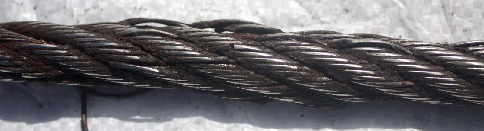
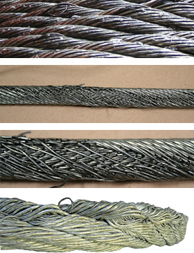
Example: Severe crown wire breaks on a 10-strand overhead crane wire rope. Crown breaks originate at the OUTSIDE of the rope at the contact point between rope and sheave/drum.
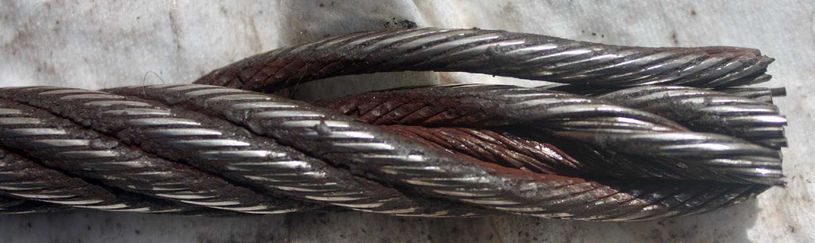
Remove the rope from service even if you find a SINGLE individual wire break which originates from inside of the rope. These so called VALLEY breaks have shown to be the cause for unexpected complete rope failures.
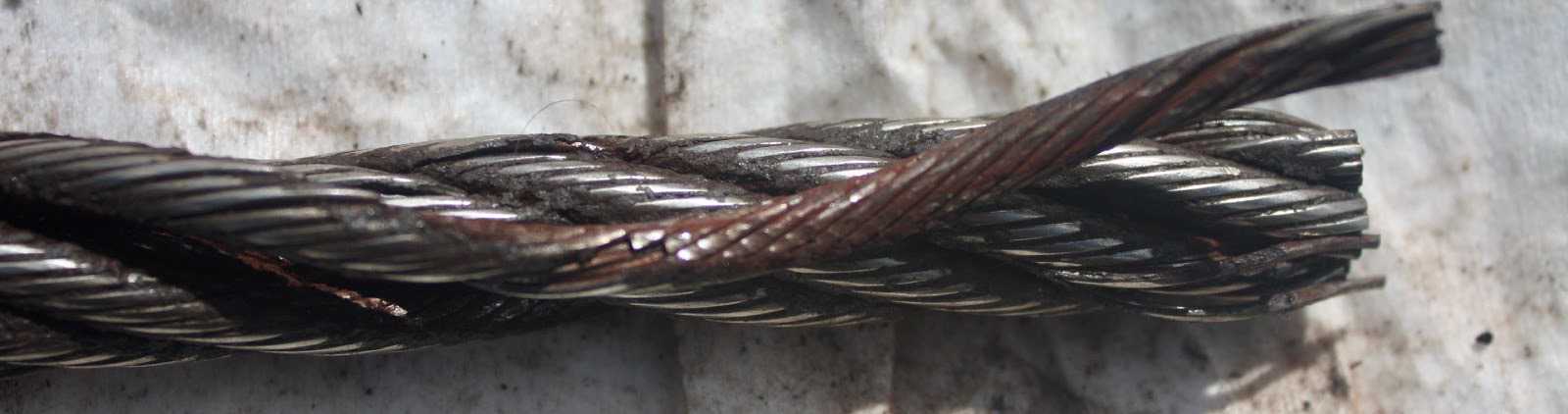
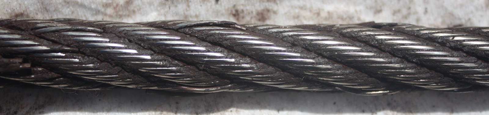
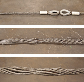
These 3 picture show what happens when you connect a left-lay rope to a right-lay rope, as done with this boom pendant extension. Both ropes are opening up to the point where the strands are nearly parallel to each other; they completely untwisted themselves and developed excessive wire breaks.
The result of such non-tensioning of the layers are looping of individual wires, completely crushed strands, total deterioration of a non-rotating rope due to gross neglect of inspection procedure.
NOTE: For a more indepth discussion on wire rope discard and inspection we suggest to attend our “Wire Rope” and “SlingMax® Rigger’s Mortis Seminar”. Call 1.800.457.9997 for details and dates.
Information about wire rope unloading, storage, handling, installation, operation, lubrication, inspection, maintenance and possible causes for rope faults is given in this article to get best service from it.
Whenever handling wire rope, take care not to drop reels or coils. This can damage wire rope and collapse the reel, making removal of the wire rope extremely difficult. Rope in a coil is unprotected and may be seriously damaged by dropping.
Wire ropes should be stored in a well ventilated, dry building or shed and shall not be in contact with the floor. If it is necessary to store them outside, cover them so that moisture cannot induce corrosion. The place should be free from dust, moisture and chemical fumes. To protect the wooden reels from the attack of termites, the floor should be cemented. Turning the reel occasionally, about half a turn, helps prevent migration of the rope lubricant. If ropes are to be stored for long time, it is advisable to examine them periodically and to apply dressing of lubricant to the top layer of rope on the drum.
Care must be taken when removing wire rope from reels or coils. When removing the rope from the reel or coil, the reel or coil MUST rotate as the rope unwinds. The Following illustrations demonstrate the right and wrong way of unreeling a rope.
For unreeling a reel, a spindle should be put through the reel and its ends jacked up to allow free rotation of the reel when the rope end is pulled. Rope in coil should be paid out from a turntable. Alternatively, where a coil is of short length, the outer end of the coil may be made free and the remainder rolled along the ground. Any attempt to unwind a rope from stationary reel or coil WILL result in a kinked rope. Looping the rope over the flange of the reel or pulling the rope off a coil while it is lying on the ground will create loops in the rope. If these loops are pulled tight, kinks will result.
A kink is a permanent deformation or reshaping of rope. Kink leads to imbalance of lay length which will cause excessive wear. In severe cases, the rope will be so distorted that it will have only a small proportion of its strength. Thus a kink in wire rope results into premature wire rope failure. One of the most common causes for its formation is improper uncoiling and unrelling. If for any reason, a loop does form, ensure that it does not tighten to cause a kink which may lead to distortion of the rope.
When reeling wire rope from one reel to another or during installation on a drum it shall always bend in the same direction: i.e. pay out from the top of the reel to the top of the other reel, or from the bottom of the reel to the bottom of the other reel as illustrated below.
If wire rope is required to be cut, it shall be seized before cutting. Seizing is warping of soft iron wire around a wire rope to prevent its wires from “flying apart” when the wire rope is cut between two adjacent seizing. Proper seizings must be applied on both sides of the place where the cut is to be made. Two or more seizing are required on each side. Either of the following seizing methods is acceptable. Method No. 1 is usually used on wire ropes over one inch in diameter. Method No. 2 is applied to ropes one inch and under.
For Method No. 1, place one end of the seizing wire in the valley between two strands. Then turn its long end at right angles to the rope and closely and tightly wind the wire back over itself and the rope until the proper length of seizing has been applied. Twist the two ends of the wire together to complete seizing. For Method No. 2, wind the wire on the rope until the proper length of seizing has been applied. Twist the two ends of the seizing wire together to complete seizing.
The length of seizing and the diameters of the wires used for seizing depend on the wire rope diameter. Length of seizing shall be greater than two times the rope diameter. Suggested seizing wire diameters are as under.
After cutting the rope it is a good practice to braze rope ends to ensure that they don"t unravel. Leave the seizings on the rope for added holding strength. As cutting a rope with a torch may result in uneven ends, it may be cut by wire rope cutter (in case of small size ropes) or by grinding. Sometime rope ends are seized with hose clamps.
It is important to maintain the manufactured condition of the rope. Take care to prevent turn being put in or taken out of the rope. If turn is put in, core protusion is likely whereas if turns are taken out, bird caging of outer wires may occur.
Installation of wire rope on a plain or grooved drum requires a great deal of care. Whenever practicable, not more than one layer of rope should be wound on a drum. Be sure to use the correct rope lay direction for the drum. This applies to smooth, as well as grooved drums. The easiest way to identify correct match between rope and drum is to look alongside the drum axis and the rope axis. The direction of rope lay and drum groove must be opposite to each other.
Make certain that wire rope is properly attached to the drum. The lay of the rope shall not be disturbed during installation, i.e. turn should not be put in nor taken out of the rope. Start winding the rope in a straight helix angle. To assist with this, some drums have a tapered steel part attached to one flange which "fills" the gap between the first turn and the flange as shown below.
The first layer must be wound tight and under tension. Take a mallet or a piece of wood and tap the wraps tightly against each other such that the rope can"t be shifted on the drum. They should not be so tight that the rope strands interlock. A too tightly wrapped first layer will not allow the next layers to have enough space between wraps. In such cases rope strands in second layer will also get interlocked as shown below.
In any case, the first layer, as well as all of the layers, must be wound on to the drum with sufficient pre-tension (about 5-10% of the rope"s WLL). If wound with no tension at all, the rope is subjected to premature crushing and flattening caused by the "under load" top layers as shown below.
After installing a new rope, it is necessary to run it through its operating cycle several times (known as break in period) under light load (approximately 10 % of the Working Load Limit) and at reduced speed. Start with light loads and increase it gradually to full capacity. This allows the rope to adjust itself to the working conditions and enable all strands and wires to become seated. Depending on rope type and construction some rope stretch and a slight reduction in rope diameter will occur as the strands and core are compacted. The initial stretch (constructional stretch) is a permanent elongation that takes place due to slight lengthening of the rope lay and associated slight decrease in rope diameter. Constructional stretch generally takes place during the first 10-20 lifts, and increases the rope length by approximately ½ % for fiber core rope, ¼ % for 6-strand steel core rope, and approaches zero % for compacted ropes.
Wire Ropes are usually made slightly larger than nominal diameter to allow for reduction in size which takes place due to the compacting of the structure under load (break in period). Keep a record of the new rope diameter after break in period for future reference.
In many cases the equipment has to be tested prior to use. Proof testing requires to purposely overloading the equipment to varying degrees. The magnitude of overloading depends on specification and which governing authority certifies the equipment. The test may impose an overload of between 10% and 100% of the equipment"s rated capacity. Under NO circumstances must the equipment be tested prior to the break in procedure of the wire rope. If you overload a rope which has not yet been broken in, you may inflict permanent damage to the rope.
Equipment consisting of wire ropes shall be operated a by well-trained operator only. A well-trained operator can prolong the service life of equipment and reduce costs by avoiding the potentially hazardous effects of overloading equipment, operating it at excessive speeds, taking up slack with a sudden jerk, and suddenly accelerating or decelerating equipment. The operator can look for causes and seek corrections whenever a danger exists. He or she can become a leader in carrying out safety measures – not merely for the good of the equipment and the production schedule, but, more importantly, for the safety of everyone concerned.
It is a common practice to leave a crane idle from one day to another or over a week end, with the rope at one position. This practice should be varied; otherwise the same part of the rope is constantly left on a bend leading to faster deterioration of that part of the rope.
Although every rope is lubricated during manufacture, to lengthen its useful service life it must also be lubricated "in the field." A rope dressing of grease or oil shall be applied during installation. Subsequently the wire rope shall be cleaned and relubricated at regular intervals before the rope shows signs of dryness or corrosion. Wire rope may be cleaned by a wire brush, waste or by compressed air to remove all the foreign material and the old lubricant from the valleys between strands and wires. After cleaning the rope, it should never be cleaned using thin oils like kerosene or gasoline as it may penetrate into the core and do away with the internal lubrication. The use of relatively fluid dressings is sometimes preferred, which can easily penetrate between the outer wires of the rope, and displace any water, which may have entered. New lubricant may be applied by a brush or may be dripped on to the rope preferably at a point where the rope opens because of bending as shown below.
When ropes are to be stored for prolonged periods or used for special operating conditions, the heavier bituminastic type of dressing is preferable to low viscosity dressings, which tend to drain off the rope, thus exposing it to corrosion.
The lubricant used must be free from acids and alkalies and should have good adhesive strength (should be such that it cannot be easily wiped off or flung off by centrifugal force). It should be able to penetrate between the wires and strands. It should not decompose, have high film strength and resist oxidation.
Frequency of lubrication depends on operating conditions. The heavier the loads, the greater the number of bends, or the more adverse the conditions under which the rope operates, the more frequently lubrication will be required.
It is essential to inspect all running ropes at regular intervals so that the rope is discarded before deterioration becomes dangerous. In most cases there are statutory and/or regulatory agencies whose requirements must be adhered to. As life of wire rope is affected by condition of drum and sheaves, their inspection and maintenance also shall be carried out.
Regular external and internal inspection of a rope shall be carried out to check for its deterioration due to fatigue, wear and corrosion. It should be checked for the following criteria. The individual degrees of deterioration should be assessed, and expressed as a percentage of the particular discard criteria. The cumulative degree of deterioration at any given position is determined by adding together the individual values that are recorded at that position in the rope. When the cumulative value at any position reaches 100 %, the rope should be discarded.
The occasional premature failure of a single wire shortly after installation may be found in the rope life and in most cases it should not constitute a basis for rope removal. Note the area and watch carefully for any further wire breaks. Remove the broken ends by bending the wire backwards and forwards. In this way the wire is more likely to break inside the rope where the ends are left tucked away between the strands. These infrequent premature wire breaks are not caused by fatigue of the wire material
The rope must be replaced if a certain number of broken wires are found which indicate that the rope has reached its finite fatigue life span. Wire rope removal/retirement criteria based on number of broken wires are given in ASME B30 and ISO 4309 specifications.
Tensile wire breaks are characterized by their typical "cup and cone" appearance as shown below. The necking down of the wire at the point of failure to form the cup and cone indicates that the failure has occurred while the wire retained its ductility.
Under normal operating conditions single wires will break due to material fatigue on the crown of a strand. Crown breaks originate at the outside of the rope at the contact point between rope and sheave/drum as shown below.
Valley breaks originate inside the rope and are seen in the valley between two strands. Valley breaks hide internal wire failures at the core or at the contact between strand and core. Valley break may indicate internal rope deterioration, requiring closer inspection of this section of rope. Picture of a rope with valley brake wires is given below.
Crown breaks are signs of normal deterioration, but valley breaks indicate an abnormal condition. Generally extreme notching and countless wire breaks is found in core (complete core failure) when valley breaks are noticed. Such condition will result in catastrophic rope failure and hence it is recommended to remove wire rope from service even if a single valley wire break is detected.
All wire rope removal/retirement criteria are based on fatigue wire breaks located at the crown of a strand. Table as per ASME specification showing maximum number of broken crown wires is as under. The removal criteria are based on the use of steel sheaves.
Broken wires at or near the termination indicates high stresses at that position. It can be due to incorrect fitting of the termination. The cause of this deterioration shall be investigated and the termination remade by shortening the rope if sufficient length remains for further use. If this is not possible, the rope shall be discarded.
In applications where major cause of rope deterioration is fatigue, broken wires will appear after a certain period of use and the number of breaks will progressively increase with usage time. In such cases it is recommended that careful periodic examination and recording of the number of broken wires is carried out with a view to establish the rate of increase in the number of broken wires. The trend can be used to plan wire rope replacement.
The round outer wires of standard wire rope will become flat on the outside due to friction when they come in contact with drums, sheaves, or other abrasive matter like sand or gravel. This is part of normal service deterioration. As shown below, when the surface wires are worn by 1/3 or more of their diameter, the rope must be replaced.
There will be always a normal continuous small decrease in diameter throughout the rope"s service life. Diameter reduction after the break in period is often due to excessive abrasion of the outside wires, internal or external corrosion, inner wire failures and/or inner wire abrasion and deterioration of a fibre core / fracture of a steel core. When core deterioration occurs, it is revealed by a more rapid reduction in diameter. Rope shall be replaced when core deterioration is observed.
Corrosion, while difficult to evaluate, is a more serious cause of degradation than abrasion. It reduces the breaking strength of the rope by reducing the metallic cross-sectional area, and also accelerates fatigue by causing surface irregularities which lead to stress cracking. Usually, it signifies a lack of lubrication. Corrosion often occurs internally before there is any visible external evidence on the rope surface. Corrosion also prevents the rope"s component parts from moving smoothly.
Visible distortion of the rope from its normal shape is termed “deformation” or damage. It is not repairable. It leads to uneven stress distribution in the rope. The magnitude of the deformation may vary from a slight cosmetic damage to total destruction of the wire rope. Kink, crushing, birdcage (also know as basket or lantern formation), core or strand protrusion and wire protrusion are various types of deformations.
Crushing or flattening of the strands can be caused by a number of different factors. These problems usually occur on multilayer spooling applications. Generally crushing conditions occur because of improper installation of the wire rope.
Birdcage is a result of a difference in length between the rope core and the outer layer of strands. Different mechanisms can produce this deformation. For example, when a rope is running over a sheave or onto the drum under a large fleet angle, it will touch the flange of the sheave or the drum groove first and then roll down into the bottom of the groove. This characteristic will unlay the outer layer of strands to a greater extent than the rope core, producing a difference in length between these rope elements. Shock loading also leads to birdcage formation. A birdcage looks as shown below.
Core or strand protrusion is a special type of birdcage in which the rope imbalance is indicated by protrusion of the core between the outer strands, or protrusion of an outer strand of the rope or strand from the core. A photograph of core protrusion is shown below.
As wire rope performance depends upon the condition of the equipment on which it operates, to increase life of a wire rope, corrective actions shall be taken after checking of wire rope at cross points, wedge sockets and other components of a machine like sheave and drums as under.
On multiple layer drums, wire rope will wear out at the crossover points from one wrap to the next. At these crossover points, the rope is subjected to severe abrasion and crushing as it is pushed over the rope "grooves" and rides across the crown of the layer beneath as shown below.
In order to extend the rope"s working life, shortening of the rope at the drum anchoring point of approx. 1/3 of the drum circumference, moves the crossover point to a different section of the rope. Now, a rope section previously not subjected to scrubbing and crushing will take the workload
Replace the sheaves with broken flanges as it enables wire rope to jump the sheave and become badly cut or sheared. If sheaves are wearing on one side, correct the alignment.
Check the sheave / bearings for ease of rotation and wear. Worn bearings cause vibration in the rope, increasing wire fatigue. Repair the bearings or replace the sheave.
The actual diameter of a wire rope is the diameter of a circumscribed circle that will enclose all the strands. It’s the largest cross-sectional measurement as shown here. You should make the measurement carefully with calipers.
The rope diameter should be measured on receipt for conformity with the specification. British Standard (B.S. 302:1987, standard steel wire rope, Part 1. Clause 5.1) allow for a tolerance of - 1% to 4 % of the nominal rope diameter.
The generally accepted method of measuring rope diameter for compliance with the standard is to use a caliper with jaws broad enough to cover not less than two adjacent stands. The measurement must be taken on a straight portion of rope at two points at least 1 meter apart. At each point two diameters at right angles should be measured. The average of the four measurement is the actual diameter.
After the rope has made the first few cycles under low load, the rope diameter should be measured at several points. The average value of all the measurements at each point must be recorded and will form the basis of comparison for all future measurements.
The measurements of the rope diameter an essential part of all inspections and examinations. It ensures the maximum diameter reduction does not exceed the recommended figure. As stated in 5.2 British standard 6570 recommends that a wire rope should be discarded when the diameter of the rope is reduced to 90% of the nominal diameter.
A comparison of the measured data with the recorded previous values can detect an abnormal rate of reduction in diameter. Coupled with assessment of previous rope examination data, the probable date of rope renewal can be predicted.
If we examine the cross-section of a six-stand wire rope, we will find that measuring the thickness of the rope over the crowns (Fig-a) will produce a higher value than measuring it over the valleys (Fig-b). The actual diameter of the rope is defined as the diameter of the circumscribing circle.
When using a conventional caliper, wire rope with an even number of outer strands (four-, six, eight-, and multi strand) ropes must be measured from crown to crown. The advantage of a proper wire rope caliper with measuring plates is that even if the measurement is carried out "incorrectly", adjacent crowns are always included, so that the actual diameter is determined at any section. (Fig-c)
Measuring the diameter of wire rope with an uneven number of outer strands (three, five, seven, or nine-strand ropes) is more complicated: a crown on the one side of the wire rope always has a valley as a counterpart on the other side of the wire rope. A conventional caliper, therefore, has to be applied diagonally to the axis of the rope, so that at any time a crown adjacent to a valley is covered. Again a wire rope caliper with measuring plate is definitely to be preferred as it always includes strands crowns.
In all cases during periodic examinations where the measurements are to be recorded, the rope should be measured as already described. Where the roundness is being checked to detect potential faults, two diameters, one at right angles to the other can be taken and noted in the records. The entry into the records might read rope diameter : 20.4/20.5mm.
After a rope has been fitted to the appliance, its length cannot be measured again accurately, with out a great deal of trouble. The purpose of measuring the length of lay is to detect any increase in the rope length which may have been caused by corrosion, core deterioration or rope rotation (unlaying). With n new rope the wire and strands should be allowed to settle into their permanent position. Six or seven lifting cycles with a light to medium load are recommended before measuring error, the measurement should be made over four lays and the length divided by four lays and the length divided by four to find the average lay length.
On eight strand ropes the eight, sixteen, twenty-four and thirty-second strands must be marked. Using a straight length of the rope and with the rope under no load, first mark any strand on the crown with a piece of chalk; this strand now become"" crown zero"". Excluding this strands, count the next eight strands and mark the eight strand with chalk. Exclude the eight strand and repeat the procedures further two times. The measured length between the outer chalk marks is then divided by four to give the lay length.
As a rough check on the overall accuracy of the chalk marking, the length of lay for eight strand ropes is approximately between 6.25 and 6.5 x the diameter of the rope e.g. using a lay length of 6.5 x rope diameter, four lay length of a 32mm diameter rope will be 32mm x 6.5 x 4=832mm.
An alternate method of measuring the rope lay is to secure the free end of the roll of adding machine paper to the rope with adhesive tape. The paper is rolled out over the rope and simultaneously the wax pencil is drawn over the paper, providing a clear print of the outer wires of the rope. The finished print can be field for comparison with later measurements.
A third method is to wrap typing carbon papers round the rope under the roll of paper. By rubbing along the paper with a piece of cardboard, the carbon marking on the underside of the paper can be confined to the tops of the strand crowns.
Wire rope is widely used in mining operations due to its high strength, light weight, and good elasticity [1,2]. However, the degree of damage sustained by the wire rope increases considerably with the increase in the usage time and due to the increase in the long-term impact of factors such as tensile bending, alternating loads, and the environment. Furthermore, this damage is inevitable if it is not addressed in time, and it can adversely affect the productivity of mining operations and threaten the safety of both the personnel and the equipment. Coal mine safety regulations have been established to ensure the productivity of mining operations; according to these regulations, mining hoist ropes must be tested every day and their scrap period is two years. If the degree of damage does not exceed the relevant provisions, their usage can be extended by no more than one year.
Various methods have been proposed for the non-destructive testing of wire ropes. Most of the current studies are focused on methods such as ultrasonic detection [3], electromagnetic detection [4], X-ray detection, and magnetostriction [5], as well as eddy current, current, and vibration detection [6,7]. The electromagnetic detection method is the most widely implemented method, owing to its demonstrated reliability and practicality. The basic principle of the electromagnetic-based leakage detection method used in this study is shown in Figure 1. The permanent magnet magnetizes the wire rope to saturation, forming a closed magnetic circuit among the wire rope, magnet, and yoke. In the presence of a damage, the original magnetic induction lines through the wire rope form a closed magnetic circuit in the air and generate a leakage magnetic field.
When using the electromagnetic detection method to detect leakage, the wire rope detection signal is mixed with a variety of sources of interference noise, including the spiral structure of the wire rope, which produces periodic changes in the strand noise; the detection of the magnetic field in an environment of complex and variable high-frequency low-amplitude noise; the shaking of the wire rope during the operation process, producing low -frequency random noise; electromagnetic interference issuing from the electromagnetic detection circuit; detection line voltage jitter; drift; and other sources of noise, all of which affect the accurate judgment of the leakage signal. To address the aforementioned challenges, Peng, F. et al. [8] applied a multi-stage filtering method based on EEMD and optimal wavelets in three-dimensional UME signal processing to effectively suppress noise interference. Zhang, J. et al. [9] proposed a new filtering system consisting of the Hilbert yellow transform and compressive-aware wavelet filtering to denoise strand and high-frequency noises. Furthermore, Chun et al. [10] designed a filter based on the multi-stage wavelet analysis of a time-domain-reflection method. Moreover, they effectively eliminated the wild-point noise and industrial frequency interference noise. The abovementioned wire rope damage signal has been studied extensively. However, because the effect of wavelet packet decomposition depends on the choice of the wavelet basis function and the number of decomposition layers, it is not an adaptive signal decomposition method. In recent years, EMD has been widely used in mechanical fault diagnosis. However, owing to the existence of endpoint effects and modal confusion, this algorithm needs to be further studied. To address the limitations of EMD and WT, Dragomiretskiy et al. [11] proposed a new adaptive time-frequency analysis method called VMD in 2014. Compared with EMD and AWT, VMD can suppress interference signals, prevent the loss of useful information, and provide a high-quality data source for subsequent feature extraction. Moreover, it has high decomposition accuracy and operational efficiency and can effectively suppress the overlap mode in a signal decomposition process.
Wire rope detection is challenging because of signal noise reduction, as well as the difficulties involved in achieving a quantitative detection process following noise reduction, owing to the complex structure, shape, and location of the wire rope, which itself produces different types of defects. To solve this problem, some scholars have conducted representative studies. Li, J. et al. designed a nondestructive wire rope inspection device which used double detection plates to collect MFL data, improved the image resolution based on a super-resolution algorithm, and finally used the AdaBoost classifier to classify the defect images [12]. Zhang, J. designed a device based on a residual magnetic field device, proposing a novel filtering system to improve the signal-to-noise ratio, and at the same time used digital image processing techniques to achieve the quantitative recognition of defect images [13,14]. Tan, X. proposed a novel test structure with a huge array of magnetoresistive sensors to effectively identify multiple types of damage and finally applied radial basis neural networks for the quantitative recognition of magnetic images [15]. W Sharatchandra Singh et al. designed an ultrasonic sensor to detect wire rope damage signals by means of ultrasonic detection method and conducted quantitative recognition research using a BP neural network [16]. Artificial neural networks and related algorithms have contributed significantly to the field of pattern recognition. However, their recognition performance is significantly influenced by several parameters and can easily fall into a local minima in the optimization process. However, SVMs have few adjustable parameters and stable operation [17]. Thus, with fewer training samples, higher diagnostic accuracy can be achieved. Therefore, in this study we used SVMs based on PSO for the identification of internal and external wire rope damages.
In summary, it is difficult to detect the internal damage of wire ropes using the existing flaw detection equipment. Therefore, we have designed a wire rope detection device based on leakage magnetism. The detection device is implemented using permanent magnets to magnetize the wire rope, axial, and radial magnetization sensors in order to obtain the wire rope defect information. At the same time, the mapping relationship between internal damage and external damage was analyzed using the finite element method to prepare for the experiment. The VMD-AWT noise reduction method is used to reduce the noise of the original signal and calculate the wavelet information entropy based on the reconstructed signal to construct a multidimensional feature vector. Finally, the PSO-SVM algorithm is proposed to effectively and quantitatively classify and identify the internal and external defects of the wire rope using a multi-dimensional feature vector dataset.
Last article, we talked about what to look for during a wire rope inspection. This month, we will talk about where and how to look for damage on a wire rope.
Much of a wire rope can be in good working order, while some sections may still be at the point of replacement or failure. This premature wear occurs at points where the rope bends over a sheave or, during drill operations, winds onto a drum during initial loading. On a drill rig, most of the time we apply a load to a winch, we either pick up a rod or piece of casing at the table, or at a rod box or rack. This means the same length of rope moves over the sheaves and enters the drum each time the operator applies a load. Wire rope wears much more quickly if subjected to bending because the outer wires and inner wires travel at differing speeds when going around a bend. Loading a rope while it bends increases these stresses.
The first method involves a rag or glove. With a rag or glove fully covering your hand, lightly grasp the rope as it moves at slow speed. External broken wires often stick up and, as the rope moves, snag the rag. The rope is then stopped, and the inspector assesses the condition by a visual examination. If he finds a problem, he marks the rope at the location of the broken wire. The inspector then checks the rope for broken-wire removal criteria and, if none are found, continues the inspection.
As a safety professional and a driller who has had steel splinters from a wire rope, I do not like this method. Inspections done this way run a high risk of hand injury for the inspector. Worst of all he may not even find all the deficiencies, because not all broken wires stick up and catch the rag.
Instead, I recommend a thorough, visual-only inspection. The method I prefer is to move the rope 2 or 3 feet at a time, and stop and visually inspect the rope looking at all sides. In cases where grease or grime cover the rope, clean with a wire brush or many defects may elude detection.
While inspecting, bend the rope to look for “valley breaks.” These breaks happen down where the strands contact each other and can be difficult to see unless the rope is bent. Valley breaks occur in wire rope applications involving small-diameter sheaves, sheave grooves that are too small and heavy loads. During inspection, pay close attention to areas of the rope that come in contact with sheaves and drums when picking up loads.
Make a habit of lubricating wire rope as part of any regular inspection. Wire rope is lubricated during manufacturing, but initial lubrication is not enough to last the life of the rope.
Lubrication of wire rope is as important as lubricating any other component or piece of machinery. Clean and dry wire rope before applying lubricant. Remember, actual lubrication occurs only when lubricant can encounter bare wires. For wire ropes used under working conditions, choose a lubricant that specifically says cable oil. Do not use WD-40, PB blaster or crankcase oil to lubricate wire rope.
The next thing we must look for during inspection is a reduction in diameter. This is the only approved way to determine the stability of the core of the rope. For this type of inspection, we need two numbers that we should have gotten upon installation of the wire rope: the diameter and the overall length.
Place a caliper on the widest point of the rope to get the correct diameter reading. Generally, ropes are manufactured larger than nominal diameter. When placed in service for the first time, diameter can reduce slightly. Therefore, make the initial measurement of a rope diameter after the rope’s initial loading or break-in period. Record this measurement as initial diameter on the inspection log. Remove a rope from service when its actual diameter falls to 95 percent of its nominal diameter.
The overall length of the rope to the inch acts as a good tool in determining core health. When a core fails, the length of a rope increases. Any increase in rope length is grounds for replacement.
Fiber rope and wire rope are widely used across the groundwater industry. Fiber rope is more commonly used in manual hoisting, such as raising up or lowering down tools. Wire rope is commonly used for mechanical hoisting operations.
The improper use of fiber rope or wire rope can result in serious incidents involving property damage, injuries, and death. Using the ropes as intended within their safe working load and maintaining them in good condition are critical in preventing rope failures.
Both types of rope include a combination of characteristics that give them certain performance traits depending on design, materials, and composition.
Wire rope is made of steel wires laid together to form a strand. These strands are laid together to form a rope, usually around a central core of either fiber or wire.
The number of strands, number of wires per strand, type of material, and nature of the core depend on the intended purpose of the wire rope. Wire rope that has many smaller wires and strands is more flexible than rope with larger-diameter wires and fewer strands. Wire rope used with sheaves and drums should have many strands to be flexible enough to bend around the sheaves and drums.
Wire ropes are classified by grouping the strands according to the number of wires per strand. The number of wires and the pattern defines the rope’s characteristics.
For example, a 6 × 7 rope indicates the rope is comprised of six strands and each individual strand is comprised of seven wires. This particular rope has large wires and is not very flexible but has good abrasion-resistant qualities. Whereas, a 6 × 19 rope has 19 wires per strand and thus is more flexible.
The more wires in a strand, the more flexible the wire rope. Likewise, the more strands in the rope, the more flexible the rope. However, the more strands in a rope and more wires in a strand, the less abrasion resistant.
Other important requirements to consider when selecting a wire rope are the breaking strength and “safe working load.” These values can be found with the use of a chart.
Most hoisting jobs use a safe working load based on a 5:1 safety factor of the wire rope’s breaking strength. However, this safety factor should be even higher if there is a possibility of injury or death from the rope breaking. For example, elevators are based on a 20:1 safety factor. Critical lifts with a danger to personnel should be calculated on a 10:1 safety factor.
Wire rope inspections are important checks on any type of rigging equipment. Wear, metal fatigue, abrasion, corrosion, kinks, and improper reeving are more important in dictating the life of a wire rope—more so than its breaking strength when new. Therefore, wire rope should be regularly inspected in accordance with OSHA and industry standards.
The frequency of inspections depends on the service conditions. Slings should be inspected each day before being used. Wire rope in continuous service or severe conditions should be inspected at least weekly and also observed during normal operation. For most other applications, wire rope should be inspected at least monthly.
Broken wires: Removing a wire rope from service due to broken wires depends on how the particular rope is being used. Finding one broken wire (or several widely spread) is usually not a problem. Regular breaks are a cause for concern and require a closer inspection. General guidelines for rope replacement due to broken wires are as follows:
Running wire ropes: Six randomly distributed broken wires in one rope lay or three broken wires in one strand in one rope lay, where a rope lay is the length along the rope in which one strand makes a complete revolution around the rope.
Pendants or standing wire ropes: More than two broken wires in one rope lay located in the rope beyond end connections or more than one broken wire in a rope lay located at an end connection. Slings: Ten randomly distributed broken wires in one rope lay or five broken wires in one strand in one rope lay.
Rotation-resistant ropes: Two randomly distributed broken wires in six rope diameters or four randomly distributed broken wires in 30 rope diameters. Valley breaks:Wire ropes with any wire breaks in between two adjoining strands should be removed from service.
Abrasion:Wire rope winding over drums or through sheaves will wear. The rope should be replaced if the outer wire exceeds one-third of the original diameter.
Crushed strands: This condition is a result of too many layers of rope wrapped around a drum. There should be no more than two layers of wire rope on the drum, especially if the rope is a type with many small wires (such as 6 × 37). Crushing also occurs by cross winding, which is a result of poor winding procedures when the rope is wound in a pile in the middle of a drum.
Corrosion: This problem is difficult to evaluate and is also much more serious than normal wear. Corrosion will often start inside the rope before it shows on the outside. A lack of lubrication is usually the cause. Wire pitting or severe rusting should be cause for immediate replacement.
Kinks: Kinks are permanent distortions. After a wire rope is kinked, it is impossible to straighten the rope enough to return it to its original strength. If a rope cannot be unkinked by hand, it should be removed from service.
Electric arc:Wire rope that has been inadvertently (or purposely) used as a ground in welding or has been in contact with a live power line will have fused or annealed wires, and must be removed from service.
Metal fatigue: This is usually caused by bending stress from repeated passes over sheaves, or from vibration such as crane pendants. Fatigue fractures can be external or internal. A larger sheave or drum size, or using a more flexible rope, may increase the rope life.
Diameter reduction: Any noticeable reduction in diameter is a serious deterioration problem. A wire rope is measured across its diameter at its widest point. Diameter reduction could be caused by one fault or a combination of faults. Wire ropes should be replaced when the reduction in diameter is more than 5% from the nominal diameter.
Wire rope stretch: Any new wire rope will stretch when the initial load is applied. After the initial stretch and a slight stretching over time during normal wear, the rope will begin to stretch at a quicker rate, which means it is approaching time for replacement.
Bird caging: This is a torsional imbalance, which is a result of mistreatment such as pulling rope through tight sheaves, being wound on too small a drum, or sudden stops.
A wire rope is lubricated during the manufacturing process. This provides the rope with protection for a reasonable time if stored under proper conditions. When the wire rope is in service, the initial lubrication will not be enough to last the lifetime of the rope. Therefore, it is usually necessary to apply a lubricant to a wire rope under working conditions. A light mineral oil can be used for lubrication. Never use old crankcase oil.
Fiber ropes are preferred for some rigging applications because they are more pliant. However, they should be used only on light loads and must not be used on objects that have sharp edges capable of cutting the rope. Fiber ropes should also not be used where they will be exposed to high temperatures, severe abrasion, or acids.
The choice of rope depends on its application. Manila is a natural fiber and has relatively high elasticity, strength, and resistance to wear and deterioration. Manila rope is generally the most common natural fiber rope used because of its quality and relative strength.
The principal synthetic fiber used for rope is nylon, which has a tensile strength nearly three times that of manila. The advantages of nylon rope are it is waterproof and has the ability to stretch, absorb shocks, and resume its normal length. Nylon also has better resistance against abrasion, rot, decay, and fungus growth as compared to natural fibers.
Avoid dragging rope through sand or dirt or pulling over sharp edges. Sand or grit between the fibers of the rope cuts the fibers and reduces its strength.
The outside appearance of fiber rope is not a good indication of its internal condition. The rope softens with use. Dampness, heavy strain, fraying and breaking of strands, and chafing on rough edges all weaken the rope considerably.
Overloading a rope may cause it to break. For this reason, fiber ropes should be inspected at regular intervals to determine their condition. Untwist the strands slightly to open the rope so the inside can be examined.
Mildewed rope has a musty odor and the inner fibers of the strands have a dark, stained appearance. Broken strands or broken yarns ordinarily are easy to identify. Dirt and sawdustlike material inside the rope, caused by chafing, indicate damage. In rope having a central core, the core should not break away in small pieces upon examination. If this happens, it indicates the rope has been overstrained.
To prevent rope failures and minimize deterioration and damage: select the right rope for the job, inspect regularly, use as intended, and properly store and maintain.


 8613371530291