
valley breaks wire rope brands
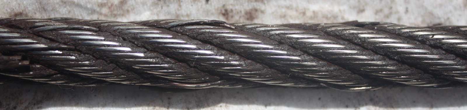
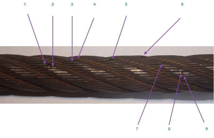
Example: Severe crown wire breaks on a 10-strand overhead crane wire rope. Crown breaks originate at the OUTSIDE of the rope at the contact point between rope and sheave/drum.
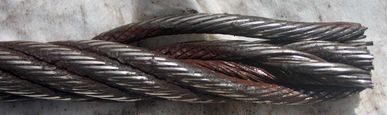
Remove the rope from service even if you find a SINGLE individual wire break which originates from inside of the rope. These so called VALLEY breaks have shown to be the cause for unexpected complete rope failures.
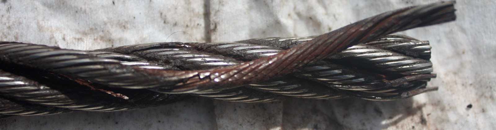
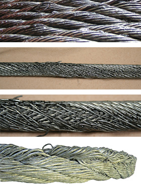
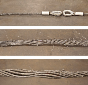
These 3 picture show what happens when you connect a left-lay rope to a right-lay rope, as done with this boom pendant extension. Both ropes are opening up to the point where the strands are nearly parallel to each other; they completely untwisted themselves and developed excessive wire breaks.
The result of such non-tensioning of the layers are looping of individual wires, completely crushed strands, total deterioration of a non-rotating rope due to gross neglect of inspection procedure.
NOTE: For a more indepth discussion on wire rope discard and inspection we suggest to attend our “Wire Rope” and “SlingMax® Rigger’s Mortis Seminar”. Call 1.800.457.9997 for details and dates.
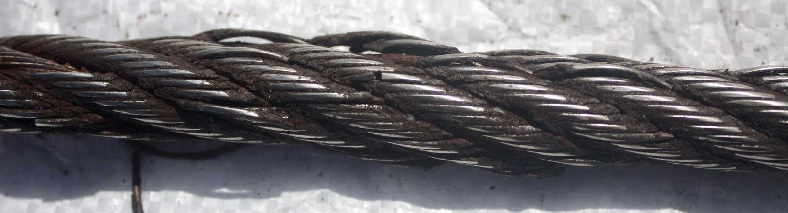
Figure 43. A wire broken under a tensile load that exceeds its strength is recognized by the “cup and cone” configuration at the fracture point (a). The necking down of the wire at this point shows that failure occurred while the wire retained its ductility. Shear-tensile fracture (b) occurs in wire subjected to a combination of transverse and axial loads. Fatigue breaks are usually characterized by squared-off ends perpendicular to the wire either straight across or Z-shaped (c&d).
Like all industrial equipment, aircraft cables and wire ropes wear while in service, and will require replacement. Though the cycle life of each cable varies based on construction and application, factors such as load and pulley condition can actually reduce this lifespan by triggering wire breaks. Not all wire breaks look the same, and understanding these differences can help detect issues in your system before they damage additional cables, or put human lives in danger. Here is a quick guide to help you understand where wire breaks occur (crowns vs. valleys), and three common examples of wire breaks (tension, fatigue, and abrasion).
Wire breaks typically occur in two different locations on the outside of wire rope or aircraft cable. The first location is on the crowns of the strands, which are the highest points with the most surface area exposure. The second location is the valleys, or the spaces between the strands. Though crown breaks typically result from normal wear and tear, valley breaks are more suspicious and may indicate issues with the pulley system or wire rope itself.
Wires that have been worn to a knife-edge thinness are characteristic of abrasion breaks. Abrasion can occur from a number of different sources, but sheaves are the most common. Remember to check sheaves for signs of wear, damage, or deformity and replace as necessary.
If you notice one end of a broken wire is cupped, and the other end resembles a cone, your wire rope likely experienced a tension break. Tension breaks result from excessive loading, causing the wires to stretch beyond their limits until they snap. Once one wire break appears, others will continue to occur if the cable is not addressed.
Fatigue damage is usually represented by zig-zag breaks with square ends. Like abrasion breaks, fatigue breaks can be triggered by a broad range of factors, including incorrect pulley size and excessive vibration. Check for worn pulleys and slack in the system to prevent issues from exacerbating.
Once you have replaced your damaged pulleys, or removed sharp obstructions in your system, begin your quote for brand new wire rope at https://strandcore.com/contact/. Our wire rope craftsmen can help you select the ideal wire rope for your application, and oftentimes provide a better solution for your existing setup. Browse our selection ofwire rope and aircraft cableonline, and do not hesitate to contact our sales team at sales@sanlo.com if you have any questions.
A wire rope is a type of cable that includes several wire strands laced together to form a single wire. Generally, both the terms “wire” and “rope” are used interchangeably with “wire rope”; however, according to the technical definition, to be labeled a wire rope, the cable must have a thickness of at least 9.52 mm. As a versatile, high load capacity alternative to natural fiber ropes such as hemp and manila, wire rope provides motion transmission through nearly all angles, tie down, counterbalance, guidance, control, or lift.
Modern wire rope was invented by Wilhelm Albert, a German mining engineer, between 1831 and 1834. He developed them in order for work in the mines in the Harz Mountains. This rope replaced weaker natural fiber ropes, like hemp rope and manila rope, and weaker metal ropes, like chain rope.
Albert’s rope was constructed of four three-stranded wires. In 1840, a Scot named Robert Stirling Newall improved upon this model. A year later in the United States, American manufacturer John A. Roebling started producing wire rope, aimed at his vision of suspension bridges. From there, other interested Americans, such as Erskine Hazard and Josiah White, used wire rope in railroad and coal mining applications. They also applied their wire rope techniques to provide lift ropes for something called the Ashley Planes project, which allowed for better transportation and increased tourism in the area.
Approximately twenty-five years later, back in Germany in 1874, the engineering firm Adolf Bleichert & Co. was founded. They used wire rope to build bicable aerial tramways for mining the Ruhr Valley. Years later they built tramways for both the Wehrmacht and the German Imperial Army. Their wire rope systems spread all across Europe, and then migrated to the USA, concentrating at Trenton Iron Works in New Jersey.
Over the years, engineers and manufacturers have created materials of all kinds to make wire rope stronger. Such materials include stainless steel, plow steel, bright wire, galvanized steel, wire rope steel, electric wire, and more. Today, wire rope is a staple in most heavy industrial processes. Wherever heavy duty lifting is required, wire rope is there to facilitate.
Wire rope is strong, durable, and versatile. Even the heaviest industrial loads may be lifted with a well-made wire rope because the weight is distributed evenly among constituent strands.
There are three basic elements of which wire ropes are composed: wire filaments, strands, and cores. Manufacturers make wire rope by taking the filaments, twisting or braiding them together into strands, and then helically winding them around a core. Because of this multiple strand configuration, wire rope is also often referred to as stranded wire.
The first component, the filaments, are cold drawn rods of metal materials of varying, but relatively small diameter. The second component, the strands, can individually consist of as few as two or as many as several dozen filaments. The last component, the core, is the central element around which strands are wrapped; wire rope cores maintain a considerable amount of flexibility, while increasing strength by at least 7.5% over the strength of fiber core wire ropes.
The helical winding of the strands around the core is known as the lay. Ropes may be right hand lay, twisting strands clockwise, or they may be left hand lay, twisting strands counter-clockwise. In an ordinary lay, the individual strands are twisted in the opposite direction of the lay of the entire rope of strands to increase tension and to prevent the rope from coming unwound. Though this is most common Lang"s lay has both the strands and the rope twisted in the same direction while alternate lays, as the name suggests alternate between ordinary and Lang style lays. While alternative rope designs are available, the helical core design is often favored, as it allows a wire cable to hold a lot of weight while remaining ductile.
There are many design aspects that wire rope manufacturers consider when they are creating custom wire rope assemblies. These include: strand gauge (varies based on application strength, flexibility, and wear resistance requirements), wire rope fittings (for connecting other cables), lay, splices, and special coatings. Specially treated steel cable and plastic coated cables, for instance, are common to many application specific variations of wire rope such as push pull cable assemblies used in transferring motion between two points.
Suppliers typically identify wire cable by listing both the number of strands and the amount of wires per strand respectively, though stranded cable may alternatively be measured by their lay and length or pitch. For example, a door-retaining lanyard wire rope is identified by its 7 x 7 construction, and wire rope used for guying purposes is identified by its 1 x 19 construction. The most common types are 6 x 19, 6 x 25, 19 x 7, 7 x 7, 7 x 19, 6 x 26, and 6 x 36.
An ungalvanized steel wire rope variety. This uncoated wire rope can also be designed to resist spinning or rotating while holding a load; this is known as rotation resistant bright wire rope.
Also called a coiled wire rope, a coiled cable is a rope made from bundles of small metal wires, which are then twisted into a coil. Wire rope and cable can come in a huge variety of forms, but coiled cables specifically provide the benefits of easy storage and tidiness. Unlike other wire ropes, coiled cables do not require a spool for storage. Because it has been coiled, the cable will automatically retract into its spring-like shape when it is not in use, making it incredibly easy to handle.
A type of high strength rope, made of several individual filaments. These filaments are twisted into strands and helically wrapped around a core. One of the most common types of wire rope cable is steel cable.
Wire rope made not as one solid piece, but as a piece made up of a series of metal links. Wire rope chain is flexible and strong, but it is more prone to mechanical failure than wire rope.
Push pull cables and controls are a particular type of control cable designed for the positive and precise transmission of mechanical motion within a given system. Unlike their counterpart pull-pull cables, these wire rope assemblies offer multidirectional control. Additionally, their flexibility allows for easy routing, making them popular in a number of industrial and commercial applications.
Iron and steel are the two most common materials used in producing wire ropes. A steel wire is normally made from non-alloy carbon steel that offers a very high strength and can support extreme stretchable forces. For even more strength and durability, manufacturers can make stainless steel wire rope or galvanized steel wire rope. The latter two are good for applications like rigging and hoisting.
Technically, spiral ropes are curved or round strands with an assemblage of wires. This gathering of wires has at least one cord situated in the opposite direction of the wire in the outer layer of the rope. The most important trait of this rope is that all the wires included are round. The biggest benefit of this category of rope is that it does not allow the entrance of pollutants, water, or moisture.
Contain an assemblage of strands placed spirally around a core. Stranded rope steel wire patterns have different layers that cross each other to form an even stronger cable or rope. Stranded ropes contain one of three types of core: a fiber core, a wire strand core, or a wire rope core.
Provide an added level of security to a manufacturing production application. Wire rope slings are made from improved plow steel wire ropes that, apart from offering added security, also provide superior return loop slings. Plow steel wire ropes improve the life of a mechanism by shielding the rope at its connection points. The key objective of wire rope slings is to enhance the safety of an application while increasing its capacity and performance. Rope slings are also available in various sling termination options, such as hook type, chokers, and thimbles.
The eye in this rope sling is made using the Flemish Splice method. Just like a typical sling, a Permaloc rope sling improves safety and provides reverse strength meaning that the uprightness of the eye does not depend on the sleeves of the metal or alloy. Additionally, permaloc rope slings offer an abrasion resistance feature that makes them long lasting.
These slings have all the features that most other slings offer. However, compared to their counterparts, Permaloc bridle slings provide better load control, wire rope resistant crushing, robust hooks and links that work for a longer duration, and help save on maintenance requirements.
Manufacturers produce wire rope for many different reasons; from cranes to playground swings, wire ropes have something for everyone. Among the many applications of wire rope are hoisting, hauling, tie down, cargo control, baling, rigging, anchoring, mooring, and towing. They can also serve as fencing, guardrails, and cable railing, among other products.
Some of the industries that make use of wire rope include industrial manufacturing, construction, marine, gas and oil, mining, healthcare, consumer goods, and transportation. Others include the fitness industry, which uses plastic coated cable products in weight machines, the theater industry, which uses black powder coated cables for stage rigging, the recreation industry, which uses plastic coated cables for outdoor playground equipment, and the electronics industry, which uses miniature wire rope for many types of electronic equipment and communications devices.
Wire ropes are typically made from cold drawn steel wire, stainless steel wire, or galvanized wire. They may also be made from a wide variety of less popular metals, including aluminum, nickel alloy, bronze, copper, and titanium. However, nearly all wire ropes, including control cables, are made from strands of cold drawn carbon steel wires. Stainless steel rope and cables are subbed in for highly corrosive environments. Galvanized cables and galvanized wire rope are popular for their increased strength and durability; these qualities are important to specialized ropes like galvanized aircraft cable.
A core may be composed of metal, fiber or impregnated fiber materials depending on the intended application. Cores may also be another strand of wire called an independent wire rope core (IWRC).
Wire rope, depending on its application, is subject to many standard requirements. Among the most common of these are the standards detailed by OSHA, ASTM International, and ISO. Per your application and industry, you’ll likely have others you need to consider. To get a full list, talk to your service provider.
To determine the safety factor, which is a margin of security against risks, the first step involves knowing the type of load that the rope will be subjected to. The load must consider the shock loads and blowing wind effects. The safety factor is characterized in ratios; typical are 4:1 and 5:1. If a ratio is 5:1, then the tensile strength of a wire rope must be five times of the load it will be subjected to. In some applications, the ratios can go up to 10:1.
By weighing all these factors carefully, the wire rope that you will buy will be safe to use and last considerably. For the best advice and guidance, though, don’t go it alone! Find a great wire rope supplier that you can trust. You’ll know you’ve found the right supplier for you when you talk to one that can not only fulfill your requirements, but shows that they are excited to go the extra mile for you. For a company like this, browse the list near the top of the page.
As the cables play an integral role in the safety of many operations and structures, careful analysis of a wire rope and all of its capabilities and features is vital. Important qualities and physical specifications you must consider include wire rope diameter, breaking strength, resistance to corrosion, difficulty of flattening or crushing, bendability, and average lifespan.
Each of the aforementioned considerations should be compatible with the specific application for which the rope is intended as well as the environment in which such operations are undertaken. Temperature and corrosive environments often require specially coated wire ropes with increased durability.
When you use your industrial wire rope, the first thing to remember is to not exceed your rope’s rated load and breaking strength. If you do not stay within these parameters, you risk causing your rope to weaken or even break.
Rust, kinks, fraying and even carefully performed splicing will all have an impact on the performance of wire ropes. To maintain the integrity of your wire rope assembly, you need to inspect them regularly and clean and lubricate them as needed. In addition, you need to store them out of the wet and cold as much as possible. Also wrap them up properly, so they are not kinked.
A high-carbon steel having a tensile strength of approximately 260,000 psi that is roughly fifteen percent stronger than Plow Steel. Most commercial wires are made from IPS.
A low carbon steel wire of approximately 10,000 psi, which is pliable and capable of repeated stresses from bending around small sheaves. This grade is effective for tillers, guys and sash ropes.
The manner in which the wires are helically wound to form rope. Lay refers specifically to the direction of the helical path of the strands in a wire rope; for example, if the helix of the strands are like the threads of a right-hand screw, the lay is known as a right lay, or right-hand, but if the strands go to the left, it is a left lay, or left-hand.
A classification of wire rope according to its breaking strength. The rank of grades according to increasing breaking strengths is as follows: Iron, Traction, Mild Plow Steel, Plow Steel, Improved Steel, Extra Improved Steel.
The act of fastening a termination to a wire rope through physical deformation of the termination about the rope via a hydraulic press or hammering. The strength is one hundred percent of the wire rope rating.
A grade of rope material that has a tensile strength range of 180,000 to 190,000 psi. Traction steel has great resistance to bending fatigue with a minimum of abrasive force on sheaves and drums, which contributes to its long use in elevators, from which the steel gets its name.
It is composed of wire strands that are braided together. Wire braid is similar to stranded wire. The difference between the two is the fact that stranded wire features strands that are bundled together, rather than braided.
Essential parts of cable assemblies, wire rope assemblies and wire rope slings that assist spliced or swaged rope ends in connecting to other cables and keeping cables and rope from unraveling.
A wire rope cable assembly is a metallic rope consisting of bundles of twisted, spiraled, or bonded wires. While the terms wire rope and cable are often used interchangeably, cables are typically designated as smaller diameter wire ropes, specifically wire ropes with a diameter less than 3/8 inch. Therefore, wire rope cable assemblies are typically utilized for lighter duty applications.
Or cable assemblies, are cables which are composed of many spiraled bundles of wire. These cables are used to support hanging objects, connect objects, pull or lift objects, secure items, and much more.
Wire rope wholesalers can sell an extensive range of wire rope and wire rope accessories at a very affordable rate as well as in bulk. Many of the additional wire rope equipment that wire rope wholesalers provide include: swivel eye pulleys, eye nuts, eye bolts, slip hooks, spring hooks, heavy duty clips, clevis hooks, turnbuckle hooks, anchor shackle pins, s hooks, rigging blocks, and much more. Wire rope fittings will generally improve the versatility of the wire and also prevent fraying.
Wire rope manufacturers produce their products in order to provide a high load capacity, versatile alternative to weaker ropes like manila rope or hemp rope. Wire rope products are used for a wide variety of motion transmission applications, among them: lifting, baling, tie down, hoisting, hauling, towing, mooring, anchoring, rigging, cargo control, guidance and counterbalance. They can also be used as railing, fencing and guardrailing.
Wire rope is a must-have for many heavy duty industrial applications. From mining to forestry to marine and beyond, there’s wire rope for almost every job. Some of the many industries in which wire rope is popular include: construction, agriculture, marine, industrial manufacturing, fitness, sports and recreation (plastic coated cables for outdoor playground equipment and sports equipment), electronics, theater (black powder coated cables for stage rigging), mining, gas and oil, transportation, security, healthcare and consumer goods.
Wire rope as we know it was invented just under 200 years ago, between 1831 and 1834. At that time, the goal was to create a rope strong enough to support work in the mines of the Harz Mountains. Invented by Wilhelm Albert, a German mining engineer, this wire rope consisted on four three-stranded wires. It was much stronger than older rope varieties, such as manila rope, hemp rope and metal chain rope.
While studying at Freiburg School of Mines, a man named L.D.B. Gordon visited the mines in the Harz Mountains, where he met Albert. After he left, Gordon wrote to his friend Robert Stirling Newall, urging him to create a machine for manufacturing wire ropes. Newall, of Dundee, Scotland, did just that, designing a wire rope machine that made wire ropes with four strands, consisting of four wires each. After Gordon returned to Dundee, he and Newall, along with Charles Liddell, formed R.S. Newall and Company. In 1840, Newall received a patent for “certain improvements in wire rope and the machinery for making such rope.”
In 1841, an American manufacturer named John A. Roebling began producing wire rope for suspension bridges. Soon after, another set of Americans, Josiah White and Erskine Hazard, started incorporating wire rope into coal mining and railroad projects, forming Lehigh Coal & Navigation Company (LC&N Co.). In 1848, wire rope from their wire rope factory in Mauch Chunk, Pennsylvania provided the lift cables needed to complete the Ashley Planes Project. This project sought to improve the performance and appearance of the freight railroad that ran through Ashley, Pennsylvania, by adding lift cables. This increased tourism and increased the railroad’s coal capacity. Before, cars took almost four hours to return; after, they took less than 20 minutes.
Wire rope likewise changed the landscape (again) in Germany, in 1874, when an engineering firm called Adolf Bleichert & Co. used wire rope to build Bi-cable aerial tramways. These allowed them to mine the Ruhr Valley. Several years later, they also used wire rope to build tramways for the German Imperial Army and the Wehrmacht. These tramways were wildly successful, opening up roads in Germany and all over Europe and the USA.
Since the 1800s, manufacturers and engineers have found ways to improve wire rope, through stronger materials and material treatments, such as galvanization, and different rope configurations. Today, wire rope makes possible many heavy industrial processes. It has become a necessity of the modern world.
Strands are made by tightly twisting or braiding individual wire together. One strand could have anywhere between two and several dozen wire filaments depending on the necessary strength, flexibility, and weight capacity.
One of the most dynamic elements of wire cables is the inner core. The strands are wrapped around the core, and it can be made of different metals, fibers, or even impregnated fiber materials. For heavy applications, cores are often made of a different strand of wire called an independent wire rope core (IWRC). An IWRC has a considerable amount of flexibility and it is still very strong. In fact, at least 7.5% of the strength increase in a wire rope can be attributed to an IWRC.
While they sometimes use other metals, like aluminum, nickel, copper, titanium, and even bronze for some applications, manufacturers primarily produce wire rope from steel. This is because steel is very strong and stretchable. Among the most common types they use are: galvanized wire, bright wire, stainless steel and cold drawn steel.
Of the wire rope steels, cold drawn carbon steel wire is most popular, although stainless steel wire rope is sometimes employed as well. Stainless steel rope is most popular for its anti-corrosive properties. Bright wire rope, a type of ungalvanized steel wire rope, is also popular. For added strength and durability, galvanized steel wire rope/galvanized steel cables are a very popular choice. Galvanized aircraft cable, for example, is always a must in aerospace.
When choosing or designing a custom wire rope for your application, suppliers consider factors such as: the environment in which the rope will function, required rust resistance, required flexibility, temperature resistance, required breaking strength and wire rope diameter. To accommodate your needs, manufacturers can do special things like: make your rope rotation resistant, color code your rope, or add a corrosion resistant coating. For instance, sometimes they specially treat and coat a cable with plastic or some other compound for added protection. This is particularly important to prevent fraying if the wire rope is often in motion on a pulley.
Manufacturers and distributors identify the differences in wire cable by listing the number of strands and the amount of wires per strand so that anyone that orders understand the strength of the cable. Sometimes they are also categorized by their length or pitch. Common examples of this include: 6 x 19, 6 x 25, 19 x 7, 7 x 19, 7 x 7, 6 x 26 and 6 x 36.
More complex wire rope identification codes connote information like core type, weight limit and more. Any additional hardware like connectors, fasteners, pulleys and fittings are usually listed in the same area to show varying strengths and degrees of fray prevention.
Cable wire rope is a heavy-duty wire rope. To give it its high strength, manufacturers construct it using several individual filaments that are twisted in strands and helically wrapped around the core. A very common example of cable wire rope is steel cable.
Spiral rope is made up an assemblage of wires with round or curved strands. The assemblage features at least one outer layer cord pointed in the opposite direction of the wire. The big advantage of spiral ropes is the fact that they block moisture, water and pollutants from entering the interior of the rope.
Similarly, stranded rope steel wire is made up of an assemblage of spirally wound strands. Unlike spiral rope, though, its wire patterns have crisscrossing layers. These layers create an exceptionally strong rope. Stranded rope may have one of three core material types: wire rope, wire strand or fiber.
Wire rope chain, like all chains, is made up of a series of links. Because it is not solid, wire rope chain is quite flexible. At the same time, it is prone to mechanical failure.
Wire rope slings are made from improved plow wire steel, a strong steel wire that offers superior return loop slings and better security. The plow wire steel also shields rope at its connection points, which extends its working life. Wire rope slings, in general, provide their applications with increased safety, capacity and performance. Wire rope sling is a rope category that encompasses a wide range of sub-products, such as permaloc rope sling, permaloc bridle slings and endless slings. These and other wire rope slings may be accompanied by a wide variety of sling terminations, such as thimbles, chokers and hooks.
Wire rope offers its user many advantages. First, design of even distribution of weight among strands makes it ideal for lifting extremely heavy loads. Second, wire rope is extremely durable and, when matched properly to the application, can withstand great stress and elements like corrosion and abrasion. In addition, it is very versatile. Its many iterations and the ways in which the rope can treated means that users can get rope custom fit for virtually any application.
Depending on the type of wire rope with which you are working and your application, you may want to invest in different accessories. Among these accessories are: wire rope clips, steel carabiners, fittings, fasteners and connections.
To ensure that your wire rope quality remains high, you must regularly inspect them for wear and degradation. The right wire rope should be selected for a particular use. Watch out for performance-impacting damage like: rust, fraying and kinks. To make sure that they stay in tip-top shape, you should also clean and lubricate them as needed. Check for this need as a part of your regular inspection.
Rope care is about more than inspection. It’s also about making an effort to use and store them properly every time you use them. For example, never exceed your rope’s rated load and breaking strength. Doing so will not only cause the weakening of your cable, but it may even cause immediate breakage. In addition, always store your wire rope cable in a dry and warm area, away from those elements that could cause premature rusting or other damage. Finally, always carefully wind your wire rope when you’re done with it, so as to avoid kinks. If you follow all these tips and treat your wire rope assemblies well, they will reward you with a long and productive service life.
Always make sure that you purchase wire rope that matches your industry and regional standards. Some of the most widely referenced standards organizations for wire rope include: ISO, ASTM International and OSHA. Talk over your specifications and application with your wire rope supplier to figure out what’s best for you.
If you’re in the market for a wire rope or a wire rope assembly, the best way to know you’re getting something that will both perform well and be safe if by working with a vetted professional. Find one among the list we’ve provided on this page. Check out their profiles to get an idea of the services and products they offer. Pick out three or four to whom you’d like to speak, and reach out. Talk to them about your specifications, standard requirements and budget. Ask about lead times and delivery options. Once you’ve spoken with all of them, compare and contrast their answers. You’ll know you’ve found the one when you talk to a wire rope company that is willing to go above and beyond for your satisfaction.

Abrasion damage may occur when the rope contacts an abrasive medium or simply when it passes over the drum and sheaves. Therefore it is vital that all components be in proper working order and of the appropriate diameter for the rope. A badly corrugated or worn sheave or drum will seriously damage a new rope, resulting in premature rope replacement.
Corrosion is very difficult to evaluate but is a more serious cause of degradation than abrasion. Usually signifying a lack of lubrication, corrosion will often occur internally before there is any visible external evidence on the rope’s surface. A slight discoloration caused by rusting usually indicates a need for lubrication which should be tended to immediately. If this condition persists, it will lead to severe corrosion which promotes premature fatigue failures in the wires and strands, necessitating the rope’s immediate removal from service.
The table shows the number of allowable wire breaks per crane type. The inspector must know the ASME standard for the equipment being inspected. The number of broken wires on the outside of the wire rope is an indication of its general condition and whether or not it must be considered for replacement. The inspector may use a type of spike to gently probe the strands for any wire breaks that do not protrude. Check as the rope runs at a slow speed over the sheaves, where crown (surface) wire breaks may be easier to see. Also examine the rope near the end connections. Keeping a detailed inspection record of the wire breaks and other types of damage will help the inspector determine the elapsed time between breaks. Note the area of the breaks and carefully inspect these areas in the future. Replace the rope when the wire breaks reach the total number allowable by ASME or other applicable specifications.
Valley breaks, or breaks in between strands, must be taken very seriously at all times! When two or more valley breaks are found in one lay-length, immediately replace the rope. Valley breaks are difficult to see; however, if you see one you can be assured that there are a few more hidden in the same area. Crown breaks are signs of normal deterioration, but valley breaks indicate an abnormal condition such as fatigue or breakage of other wires such as those in the core.
Once crown and valley breaks appear, their number will steadily and quickly increase as time goes on. The broken wires should be removed as soon as possible by bending the broken ends back and forth with a pair of pliers. In this way the wire is more likely to break inside the rope where the ends will be tucked away. If the broken wires are not removed they may cause further damage.
It is important to check and record a new rope’s actual diameter when under normal load conditions. During the life of the rope the inspector should periodically measure the actual diameter of the rope at the same location under equivalent loading conditions. This procedure if followed carefully reveals a common rope characteristic -- after an initial reduction, the overall diameter will stabilize and slowly decrease in diameter during the course of the rope’s life. This condition is normal. However, if diameter reduction is isolated to one area or happens quickly, the inspector must immediately determine (and correct, if necessary) the cause of the diameter loss, and schedule the rope for replacement.
Crushing or flattening of the strands can be caused by a number of different factors. These problems usually occur on multilayer spooling conditions but can occur by simply using the wrong wire rope construction. Most premature crushing and/or flattening conditions occur because of improper installation of the wire rope. In many cases failure to obtain a very tight first layer (the foundation) will cause loose or "gappy" conditions in the wire rope which will cause rapid deterioration. Failure to properly break-in the new rope, or worse, to have no break-in procedure at all, will cause similar poor spooling conditions. Therefore, it is imperative that the inspector knows how to inspect the wire rope as well as how that rope was installed.
Shockloading (birdcaging) of the rope is another reason for replacement of the rope. Shockloading is caused by the sudden release of tension on the wire rope and its resultant rebound from being overloaded. The damage that occurs can never be corrected and the rope must be replaced.
High stranding may occur for a number of reasons such as failure to properly seize the rope prior to installation or maintain seizing during wedge socket installation. Sometimes wavy rope occurs due to kinks or a very tight grooving problem. Another possibility is simply introducing torque or twist into a new rope during poor installation procedures. This condition requires the inspector to evaluate the continued use of the rope or increase the frequency of inspection.
Wire Rope is an item often found on Wire Rope Cranes. Unfortunately, though these wires are not unbreakable and can/will succumb to the pressure of constant use and may potentially snap when in use. Which is why it is important to know what to look out for in an unsafe wire rope, the Government of Canada recommends a visual inspection of the wire before each use, but full inspections should be undertaken by a trained professional periodically. This article will cover what causes wire ropes to break, what your professional inspector will do to ensure your rope is safe and what you can look out for when completing your frequent inspection to ensure the rope is safe to work with.
When you hear the term wire rope you may picture in your mind a metal and seemingly unbreakable rope, and through wire ropes, can and will stand up better than many other rope types it is unfortunately not unbreakable. Some things that can cause a wire rope to break include:
Kinks caused by improper installation of a rope, sudden release of a load or knots that were made to shorten a rope can cause the rope to become compromised
Many of these causes can be minimized by the use of proper crane design and rope maintenance procedures, most of these causes though are unavoidable and are considered to be part of a normal rope life. The two main causes that are considered unavoidable are crushing and internal and external fatigue.
Many wire ropes are subject to a lot of repetitive bending over a sheave, which causes the wire to develop cracks in its individual wires. These broken wires often develop in the sections that move over sheaves. This process will become escalated if a rope travels on and off of a grooved single layer drum, which causes this to go through a bending cycle. Tests in the past have shown that winding on a single layer drum is equal to bending over a sheave because it causes similar damage.
Fatigue breaks often develop in segments as stated before these segments are usually the part of the rope surface that comes into direct contact with a sheave or drum. Because this is caused by external elements rubbing, oftentimes these breakages are external and visible for the eye to see. Once broken wires start to appear, it creates a domino effect and quickly much more will appear. Square ends of wires are common for fatigue breaks. These breaks are considered a long-term condition and are to be considered part of the normal to the operating process.
Internal Breaks,these breaks can develop over time-based upon the loading of the hoist. Many ropes are made of a torque-balanced multi-strand design, which comprises of two or more layers of strands. A torque balance is created in multi-strand ropes, by layering the outside and inside ropes in opposite directions. Multi-strand ropes offer much more flexibility and have a more wear-resistant profile. Though the wires in these ropes touch locally and at an angle, which causes them to be subject to both the effect of radial load, relative motion between wires and bending stresses when bent on sheaves or drums.
Nicking and fatigue patterns such as the ones discussed before occur in Independent Wire Rope Cores or IWRC ropes. IWRC ropes have outer wires of the outer strands, which have a larger diameter than the outer core strands. This helps to minimize inner strand nicking between the outer strands of the IWRC. The outer strands and the IWRC strands are approximately parallel. Often their neighbouring strands support these outer strands while the outer IWRC wires are relatively unsupported.
With these geometrical features it allows for the wire to fluctuate under tensile loads, the outer IWRC wires are continuously forced into valleys in between the outer strand wires and then released. This system results in secondary bending stresses which leads to a large number of core wires with fatigue breaks. These breaks are often close together and form in groups. This eventually leads to the IWRC breaking or completely disintegrating into short pieces of wire that lay, half a length long. This condition is often called complete rope core failure.
It is as the IWRC fails, and the outer strands lose their radial support then valley breaksform. Valley breaks occur when the outer strand wires bear against each other tangentially. This results in interstrand nicking, which restricts the movement of strands within the rope; without the freedom to move, secondary fatigue breaks occur in the outer strands, which will develop a stand tangent points. These breaks occur in the valleys between the outer strands hence why they are called valley breaks.
So to go over what we just learned, internal broken wires occur often in ropes that are operated with large diameter sheaves and high factors of safety. These breakages can occur when a reeving system incorporates sheaves lined with plastic or all plastic sheaves; these sheave units offer more elastic support than their steel counterparts. Which causes the pressure between outer wires and sheave grooves to be reduced to the point where the first wire breaks will occur internally.
If a section of a rope travels on and off of a grooved multi-layer drum, then it goes through what is called a bending cycle. The bending cycle occurs by a section of rope spooling in the first layer and is bent around the smooth drum surface, but when the second layer rolls around the rope section in the first layer will be spooled over. This causes the first layer to become compressed and damaged on the upper side by the second rope layer. With continued spooling the rope layers in the second and higher layers will, in turn, be damaged on both sides during contact with their neighbouring rope layers. This damage is caused both by the compression of the rope and by the rope laying on a rough surface.
Accelerated wear occurs where the point of the rope is squeezed between the drum flange and the previous layer. Often times the slap of rope at the crossover points causes peening, martensitic embrittlement and/or wire plucking, further associated rope damage is caused when the rope crosses over from layer to layer on a drum.
Also, if the lower wire rope areas where not spooled under sufficiently high tension the lower wraps can become displaced by the additional rope sections which would allow for these new rope sections to slide down in between them, which will lead to severe rope damage.
Many regulators have decided that the Statutory Life Policy be overly wasteful and they tend to use the Retirement for Clause Policy. A wire rope deteriorates slowly over its entire service, but to be aware of the state of deterioration, a wire rope must be periodically inspected. Moderate deterioration is normally present, and low levels of deterioration do not justify retirement. Which is why you have wire rope inspections to monitor the normal process of deterioration. This ensures that the rope can be retired before it can become dangerous. Besides, these inspections can detect unexpected damage or corrosion on the wire rope which will allow you to take corrective actions to ensure the longevity of the wire rope.
This system is useful for detecting external rope deterioration. To use this approach, the inspector will lightly grab the rope with a rag. The inspector then glides the cloth over the rope. Often times external broken wires will porcupine (stick up). When the rope moves along the wire it will be snagged on the broken wire. The inspectorwill then stops dragging the cloth along the wire and visually inspects the condition of the wire.
Frequently broken wires often do no porcupine, which is why a different test procedure must be utilized. This test involves moving along the rope two or three feet at a time and visually examining the rope. This method though can become tiresome because oftentimes the rope is covered in grease and many internal and external defects will avoid detection through this method.
Another method involves measuring the wire ropes diameter. This involves comparing the diameter of the current rope to the original rope’s diameter. Changes in the diameter of the rope indicate external and/or internal rope damage. This method is not perfect because many different wire breakages damages do not change the diameter of the rope.
You can also check for several visible signs of distributed losses of the metallic cross-sectional area. This is often caused by corrosion, abrasion and wear. To internally check for damage, you can insert a marlinspike under two strands and rotate it to lift the strands and open the rope.
Visual inspections are often not well suited for the detection of internal rope damage. This means that they have limited value as the only means of wire rope inspection. Though visual inspections do not require special machines. When completed by a knowledgeable and experienced rope examiner through visual inspections can be valuable tools for evaluating rope degeneration.
Electromagnetic Inspections or EM gives a detailed insight into the exact condition of a rope. EM is a very reliable inspection method and is a universally accepted method for inspecting wire ropes for mining, ski lifts and other similar industries. There are two distinct EM inspection methods, which have been developed to classify defects called Localized-Flaw (LF Inspection) and Loss-of-Metallic-Area Inspection (LMA Inspection type)
LF Inspection is similar to the rag-and-visual method. This inspection method is suited primarily for finding localized flaws, such as broken wires. Which is why small hand-held LF instruments are called electronic rags.
Electromagnetic and visual wire rope inspection methods are like peanut butter and jelly or cookies and milk they are the perfect combination, and both are essential for safe rope operation. Which is why both methods are often used to ensure maximum safety.
A program that involves periodic inspections is extremely effective. To establish baseline data for future inspections, a wire rope inspection program should begin with an initial inspection after a break-in period. Then the inspections should follow at scheduled intervals, with documentation of the ropes deterioration over its entire service life.
For multi-strand ropes often times visual inspections are ineffective which is why statutory life policy for a ropes retirement is often adopted. This means that these ropes are often discarded long before they should be meaning millions of dollars’ worth of perfectly good wire ropes are being thrown away annually.
Some people have suggested that non-rotating ropes should not be used if cranes use a single layer winding on a drum. Following this line of thought, this would mean multi-strand ropes should be used only when winding on multi-layer drums. This would cause wires to break the surface faster than internal wire damage can occur, these non-rotating wire ropes will be replaced long before internal fatigue can set in.
When internal broken wires are the problem electromagnetic rope testing can be the solution. Though there are some factors one needs to take into account such as certain regulations require rope retirement when a certain number of broken wires per unit of rope length exceed a set limit. This discard number that is specified in retirement standards refers solely to external wire breaks. This means the condition of a wire rope with internal breaks is therefore left up to the inspector.
Though you also need to take into account detailed detection and quantitative characterization of internal broken wires in ropes with many breaks and cluster breaks could be a problem. These difficulties are caused by the fact that electromagnetic wire rope can be influenced by several parameters such as:
Clusters of broken wires can cause an additional problem because the relative position of broken wires concerning each other within the rope is not known
Broken wires with zero or tight gap widths are not detectable by electromagnetic inspection because they do not have a sufficient magnetic leakage flux.
When you consider all of this you can quickly realize that you can only estimate the number of broken wires that have formed on a wire rope. You can use the LF trace for the detection of broken wires, though unfortunately it is not quantitative so it cannot be used to estimate the number of broken wires. Though it is good to note that if any internal broken wires are present an LMA trace will show rapid relatively small variations of a cross-section.
An electromagnetic inspection will help to enhance the accuracy and reliability of the inspection, by combining visual and EM methods they will be able to detect deterioration at the earliest stages. The inspections can be then used as an effective preventive maintenance tool. For example, the inspector early on detects corrosion, and you immediately apply the corrective action of improving the lubrication of the wire rope.
Wire ropes should be inspected by a certified inspector when installing it, and periodically throughout its life cycle. A wire rope should go through a quick, but thorough inspection every day that you use it at the beginning and end of each shift and you should keep records of all inspections. Ensure that your certified wire rope inspector uses a combination of visual inspection methods and electromagnetic inspection methods because this will ensure the optimum safety and longevity of the rope. This is especially true for ropes that are more likely to develop internal broken wires, and inspections completed by a certified inspector is the best way of having a preventive maintenance program and extending the life of your wire rope.
Queensland Division of Workplace Health and Safety, “Non-rotating hoist wire ropes, multi fall configurations, Health and Safety Alert,” http://www.whs.qld.gov.au/alerts/97-i-5.pdf
Verreet, R. “Wire rope damage due to bending fatigue and drum crushing,” O.I.P.E.E.C.(International Organization for the Study of the Endurance of Wire Rope) Bulletin 85, June 2003, Reading (UK), ODN 0738, pp. 27-46.

Die drawn and swaged ropes fall into the compacted category. Compacting serves several purposes. By flattening the outer wires, metallic area increases allowing for a higher breaking strength as well as improved crushing and abrasion resistance. In addition, the compaction minimizes inter-strand nicking and thereby improves fatigue resistance.
In the inspection of compacted rope designs, again it is imperative to follow the basic inspection guidelines and use both visual and actual measuring techniques to determine the remaining life of the rope. In fact, actual measuring techniques are very important when inspecting these ropes. While corrosion is relatively easy to visually determine, diameter reduction may not be due to the compacted rope’s appearance. Therefore the inspector must regularly measure for diameter reduction and closely examine the rope for lay lengthening. Measurements must be recorded and the rope monitored for sudden variations.
By and large the most difficult retirement criteria to determine in compacted ropes is wire breaks. These breaks may not protrude from the rope due to the compaction and can be easily overlooked. Because of this, the inspector must slowly and carefully examine the rope, especially in those areas passing over drums and sheaves or in areas where problems existed in previous ropes.
A wire break may appear as nothing more than a crack in the wire, and again can be easily overlooked. If the inspector notes a "flaw" in a wire, it should be carefully checked. The inspector should carry some type of magnifying device to determine if a flaw is actually a break. If a break has occurred, thoroughly check the area for additional breaks, both on the crown and in the valleys. Remember, valley breaks in round strand ropes are difficult to determine; compaction only increases the difficulty. The inspector must be slow and methodical in inspecting compacted ropes; a quick check will reveal nothing.
Overall, perhaps the most important inspection technique is recognizing the limits of wire rope. While it’s true that compacted and plastic-infused ropes are more durable, neglect and abuse will still quickly end the rope’s life. There is no substitute for proper installation, handling and inspection techniques in combination with a preventative maintenance program.
Reeving failures have been a leading cause of accidents in our trade. They were thirty years ago when Wilbert A Lucht wrote his article, “Sheave Design vs Wire Rope Life” (reprinted in the June issue ofWire Rope News, page 26), and are still today.
A Crane is a combination of two simple machines. One is a lever, and the other is a block and tackle. Both increase the machinal advantage of a crane’s lifting capability. However, the block and tackle (sheaves and wire rope, referred to as reeving) are “used-up” as the crane works.
The sheave differs from a “pulley” or roller importantly. Both change the direction of the rope and increase the mechanical advantage — pulling power. However, the sophisticated sheave does the same but also maintains the cross-section shape of the rope, critical to reducing wear, and the rope strength — if properly sized.
A Sheave gauge is being used to check the groove size by a crane inspector in Fig. 1. These gauges have the maximum size of the groove recommended for the rope that is installed on the crane.
An oversize or worn-out sheave acts just like a pulley, not preserving the rope’s shape, Fig. 2. Instead of the load being supported by at least three strands at the bottom of the groove, all the load is concentrated on one. With less support, increased pressure equals more significant sheave wear. There is another terrible consequence of improper groove support — premature wire breaks and internal wire wear. When the unsupported rope is bent over a sheave and loaded, the strands must adjust by sliding along each other. Sliding causes strand to strand nicking and “valley” wire breaks, a severe reduction in the rope’s life, Fig. 3.
The consequence of sheaves not correctly sized to the wire rope installed on them is accelerated wear and broken wires. How important is this to the crane owner depends on how many hours of operation per inspection interval. Some cranes aren’t used much, and owners aren’t too concerned with groove size, just so the grooves are “kind of” smooth — wrong. Current standards allow only one valley break, as shown in Fig.3.
The point is, to achieve a predictable rope life — the sheave must support about 150 degrees of the rope at the bottom of the groove, or the rope will flatten when loaded and be weaken — got that!

The following is a fairly comprehensive listing of critical inspection factors. It is not, however, presented as a substitute for an experienced inspector. It is rather a user’s guide to the accepted standards by which wire ropes must be judged. Use the outline to skip to specific sections:
Rope abrades when it moves through an abrasive medium or over drums and sheaves. Most standards require that rope is to be removed if the outer wire wear exceeds 1/3 of the original outer wire diameter. This is not easy to determine, and discovery relies upon the experience gained by the inspector in measuring wire diameters of discarded ropes.
All ropes will stretch when loads are initially applied. As a rope degrades from wear, fatigue, etc. (excluding accidental damage), continued application of a load of constant magnitude will produce incorrect varying amounts of rope stretch.
Initial stretch, during the early (beginning) period of rope service, caused by the rope adjustments to operating conditions (constructional stretch).
Following break-in, there is a long period—the greatest part of the rope’s service life—during which a slight increase in stretch takes place over an extended time. This results from normal wear, fatigue, etc.
Thereafter, the stretch occurs at a quicker rate. This means that the rope has reached the point of rapid degradation: a result of prolonged subjection to abrasive wear, fatigue, etc. This second upturn of the curve is a warning indicating that the rope should soon be removed.
In the past, whether or not a rope was allowed to remain in service depended to a great extent on the rope’s diameter at the time of inspection. Currently, this practice has undergone significant modification.
Previously, a decrease in the rope’s diameter was compared with published standards of minimum diameters. The amount of change in diameter is, of course, useful in assessing a rope’s condition. But, comparing this figure with a fixed set of values can be misleading.
As a matter of fact, all ropes will show a significant reduction in diameter when a load is applied. Therefore, a rope manufactured close to its nominal size may, when it is subjected to loading, be reduced to a smaller diameter than that stipulated in the minimum diameter table. Yet under these circumstances, the rope would be declared unsafe although it may, in actuality, be safe.
As an example of the possible error at the other extreme, we can take the case of a rope manufactured near the upper limits of allowable size. If the diameter has reached a reduction to nominal or slightly below that, the tables would show this rope to be safe. But it should, perhaps, be removed.
Today, evaluations of the rope diameter are first predicated on a comparison of the original diameter—when new and subjected to a known load—with the current reading under like circumstances. Periodically, throughout the life of the rope, the actual diameter should be recorded when the rope is under equivalent loading and in the same operating section. This procedure, if followed carefully, reveals a common rope characteristic: after an initial reduction, the diameter soon stabilizes. Later, there will be a continuous, albeit small, decrease in diameter throughout its life.
Deciding whether or not a rope is safe is not always a simple matter. A number of different but interrelated conditions must be evaluated. It would be dangerously unwise for an inspector to declare a rope safe for continued service simply because its diameter had not reached the minimum arbitrarily established in a table if, at the same time, other observations lead to an opposite conclusion.
Corrosion, while difficult to evaluate, is a more serious cause of degradation than abrasion. Usually, it signifies a lack of lubrication. Corrosion will often occur internally before there is any visible external evidence on the rope surface.
Pitting of wires is a cause for immediate rope removal. Not only does it attack the metal wires, but it also prevents the rope’s component parts from moving smoothly as it is flexed. Usually, a slight discoloration because of rusting merely indicates a need for lubrication.
Severe rusting, on the other hand, leads to premature fatigue failures in the wires necessitating the rope’s immediate removal from service. When a rope shows more than one wire failure adjacent to a terminal fitting, it should be removed immediately. To retard corrosive deterioration, the rope should be kept well lubricated with a clear wire rope lube that can penetrate between strands. In situations where extreme corrosive action can occur, it may be necessary to use galvanized wire rope.
Kinks are tightened loops with permanent strand distortion that result from improper handling when a rope is being installed or while in service. A kink happens when a loop is permitted to form and then is pulled down tight, causing permanent distortion of the strands. The damage is irreparable and the sling must be taken out of service.
Doglegs are permanent bends caused by improper use or handling. If the dogleg is severe, the sling must be removed from service. If the dogleg is minor, exhibiting no strand distortion and cannot be observed when the sling is under tension, the area of the minor dogleg should be marked for observation and the sling can remain in service.
Bird caging results from torsional imbalance that comes about because of mistreatment, such as sudden stops, the rope being pulled through tight sheaves, or wound on too small a drum. This is cause for rope replacement unless the affected section can be removed.
Particular attention must be paid to wear at the equalizing sheaves. During normal operations, this wear is not visible. Excessive vibration or whip can cause abrasion and/or fatigue. Drum cross-over and flange point areas must be carefully evaluated. All end fittings, including splices, should be examined for worn or broken wires, loose or damaged strands, cracked fittings, worn or distorted thimbles and tucks of strands.
After a fire or the presence of elevated temperatures, there may be metal discoloration or an apparent loss of internal lubrication. Fiber core ropes are particularly vulnerable. Under these circumstances the rope should be replaced.
Continuous pounding is one of the causes of peening. This can happen when the rope strikes against an object, such as some structural part of the machine, or it beats against a roller or it hits itself. Often, this can be avoided by placing protectors between the rope and the object it is striking.
Another common cause of peening is continuous working-under high loads—over a sheave or drum. Where peening action cannot be controlled, it is necessary to have more frequent inspections and to be ready for earlier rope replacement.
Below are plain views and cross-sections show effects of abrasion and peening on wire rope. Note that a crack has formed as a result of heavy peening.
Scrubbing refers to the displacement of wires and strands as a result of rubbing against itself or another object. This, in turn, causes wear and displacement of wires and strands along one side of the rope. Corrective measures should be taken as soon as this condition is observed.
Wires that break with square ends and show little surface wear have usually failed as a result of fatigue. Such fractures can occur on the crown of the strands or in the valleys between the strands where adjacent strand contact exists. In almost all cases, these failures are related to bending stresses or vibration.
If diameter of the sheaves, rollers or drum cannot be increased, a more flexible rope should be used. But, if the rope in use is already of maximum flexibility, the only remaining course that will help prolong its service life is to move the rope through the system by cutting off the dead end. By moving the rope through the system, the fatigued sections are moved to less fatiguing areas of the reeving.
The number of broken wires on the outside of a wire rope are an index of its general condition, and whether or not it must be considered for replacement. Frequent inspection will help determine the elapsed time between breaks. Ropes should


 8613371530291