
valley breaks wire rope made in china
Example: Severe crown wire breaks on a 10-strand overhead crane wire rope. Crown breaks originate at the OUTSIDE of the rope at the contact point between rope and sheave/drum.
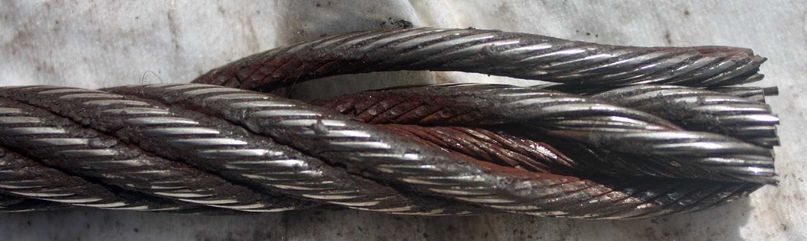
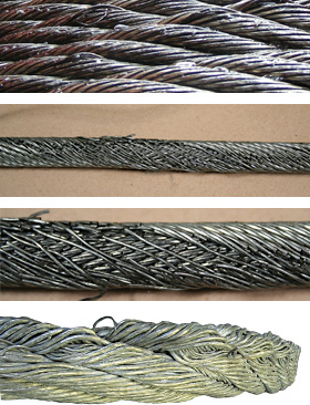
Remove the rope from service even if you find a SINGLE individual wire break which originates from inside of the rope. These so called VALLEY breaks have shown to be the cause for unexpected complete rope failures.
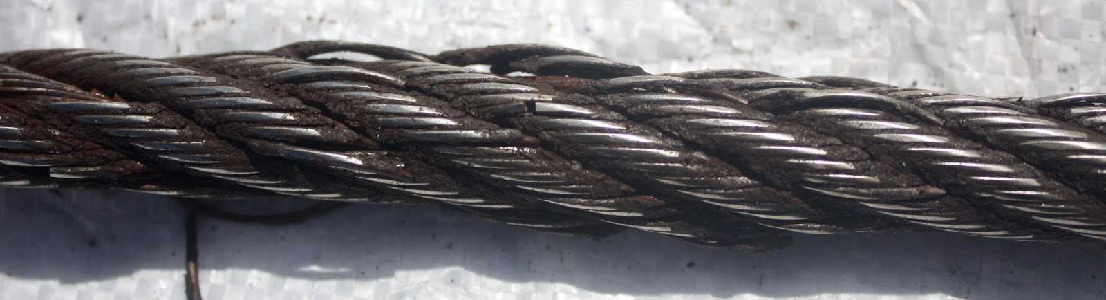
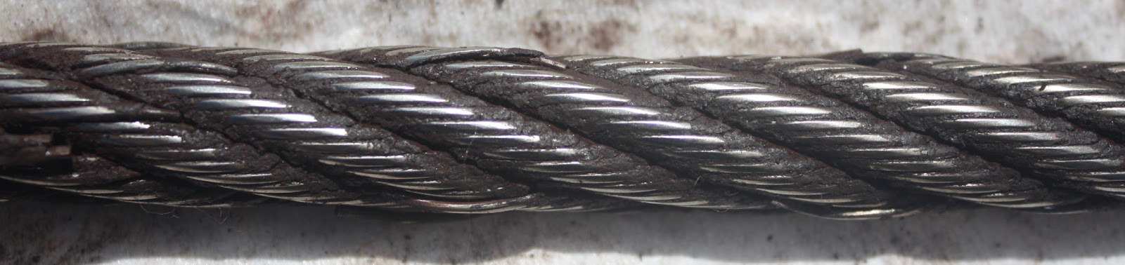
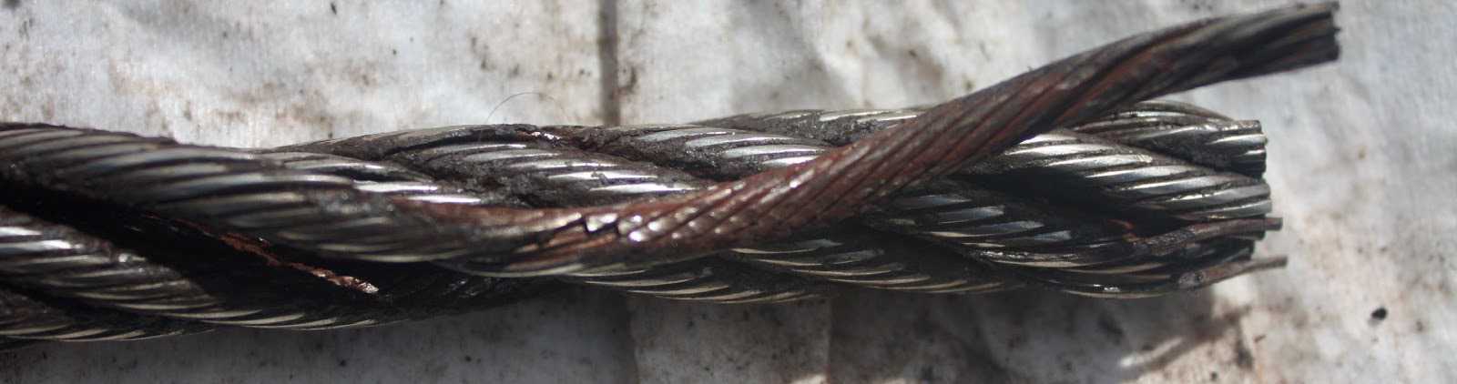
These 3 picture show what happens when you connect a left-lay rope to a right-lay rope, as done with this boom pendant extension. Both ropes are opening up to the point where the strands are nearly parallel to each other; they completely untwisted themselves and developed excessive wire breaks.
The result of such non-tensioning of the layers are looping of individual wires, completely crushed strands, total deterioration of a non-rotating rope due to gross neglect of inspection procedure.
NOTE: For a more indepth discussion on wire rope discard and inspection we suggest to attend our “Wire Rope” and “SlingMax® Rigger’s Mortis Seminar”. Call 1.800.457.9997 for details and dates.
As specialist for manufacturing quality steel wire ropes over 20 years, our company can supply strong, durable and reliable ropes that capable to minimize your downtime and maximize cost effectiveness. Decades of experience we owned make us know clearly the work you do and capable to provide professional guidance.
We select the best steel or stainless steel as raw material for wire rope manufacturing. Our products are manufactured under strict quality managements and test before they leave the factory.
Our engineers can provide professional advice about picking up optimal steel wire ropes for their application, installation guidance to ensure maximum return in their wire rope system.
If you are going to pick up steel wire ropes that suit your project perfectly, you must have an ideal about the construction about them. Our company can supply bright wire rope, galvanized wire rope, stainless steel wire rope, compacted wire rope, rotation resistant wire ropes, mining wire rope, elevator wire rope, crane wire rope and gas & oilfield wire ropes. Here are some details to solve the problem that may puzzle you whether you are browsing the web or picking up steel wire ropes.
Bright steel wire ropes mean no surface treatment is applied to the rope. Therefore, they have the lower price among these three wire ropes. Generally, they are fully lubricated to protect the rope from rust and corrosion.
Galvanized steel wire ropes feature compressed zinc coating for providing excellent corrosion resistance. With higher break strength yet lower price than stainless steel, galvanized steel wire ropes are widely used in general engineering applications such as winches and security ropes.
Stainless steel wire ropes, made of quality 304, 305, 316 steels, are the most corrosive type for marine environments and other places subjected to salt water spray. Meanwhile, bright and shiny appearance can be maintained for years rather than dull as galvanized steel wire ropes.
Steel wire ropes are composed of multiple strands of individual wires that surrounding a wire or fiber center to form a combination with excellent fatigue and abrasion resistance. These wires and strands are wound in different directions to from different lay types as follows:
Beside above lay types, alternative lay ropes which combine regular lay and lang lay together and ideal for boom hoist and winch lines, can also be supplied as your request.
Two main methods about seizing steel wire ropes in conjunction with soft or annealing wire or strands to protect cut ends of the ropes form loosening.
Rope diameter is specified by the user and is generally given in the equipment manufacturer’s instruction manual accompanying the machine on which the rope is to be used.
Rope diameters are determined by measuring the circle that just touches the extreme outer limits of the strands— that is, the greatest dimension that can be measured with a pair of parallel-jawed calipers or machinist’s caliper square. A mistake could be made by measuring the smaller dimension.
The right way to unreel.To unreel wire rope from a heavy reel, place a shaft through the center and jack up the reel far enough to clear the floor and revolve easily. One person holds the end of the rope and walks a straight line away from the reel, taking the wire rope off the top of the reel. A second person regulates the speed of the turning reel by holding a wood block against the flange as a brake, taking care to keep slack from developing on the reel, as this can easily cause a kink in the rope. Lightweight reels can be properly unreeled using a vertical shaft; the same care should be taken to keep the rope taut.
The wrong way to unreel.If a reel of wire rope is laid on its flange with its axis vertical to the floor and the rope unreeled by throwing off the turns, spirals will occur and kinks are likely to form in the rope. Wire rope always should be handled in a way that neither twists nor unlays it. If handled in a careless manner, reverse bends and kinks can easily occur.
The right way to uncoil.There is only one correct way to uncoil wire rope. One person must hold the end of the rope while a second person rolls the coil along the floor, backing away. The rope is allowed to uncoil naturally with the lay, without spiraling or twisting. Always uncoil wire rope as shown.
The wrong way to uncoil.If a coil of wire rope is laid flat on the floor and uncoiled by pulling it straight off, spirals will occur and kinking is likely. Torsions are put into the rope by every loop that is pulled off, and the rope becomes twisted and unmanageable. Also, wire rope cannot be uncoiled like hemp rope. Pulling one end through the middle of the coil will only result in kinking.
Great stress has been placed on the care that should be taken to avoid kinks in wire rope. Kinks are places where the rope has been unintentionally bent to a permanent set. This happens where loops are pulled through by tension on the rope until the diameter of the loop is only a few inches. They also are caused by bending a rope around a sheave having too severe a radius. Wires in the strands at the kink are permanently damagedand will not give normal service, even after apparent “re-straightening.”
When wire rope is wound onto a sheave or drum, it should bend in the manner in which it was originally wound. This will avoid causing a reverse bend in the rope. Always wind wire rope from the top of the one reel onto the top of the other.Also acceptable, but less so, is re-reeling from the bottom of one reel to the bottom of another. Re-reeling also may be done with reels having their shafts vertical, but extreme care must be taken to ensure that the rope always remains taut. It should never be allowed to drop below the lower flange of the reel. A reel resting on the floor with its axis horizontal may also be rolled along the floor to unreel the rope.
Wire rope should be attached at the correct location on a flat or smooth-faced drum, so that the rope will spool evenly, with the turns lying snugly against each other in even layers. If wire rope is wound on a smooth-face drum in the wrong direction, the turns in the first layer of rope will tend to spread apart on the drum. This results in the second layer of rope wedging between the open coils, crushing and flattening the rope as successive layers are spooled.
A simple method of determining how a wire rope should be started on a drum. The observer stands behind the drum, with the rope coming towards him. Using the right hand for right-lay wire rope, and the left hand for left lay wire rope, the clenched fist denotes the drum, the extended index finger the oncoming rope.
Clips are usually spaced about six wire rope diameters apart to give adequate holding power. They should be tightened before the rope is placed under tension. After the load is placed on the rope, tighten the clips again to take care of any lessening in rope diameter caused by tension of the load. A wire rope thimble should be used in the eye of the loop to prevent kinking.
U-bolt Clips.There is only one correct method for attaching U-bolt clips to wire rope ends, as shown in TheRightWayimage below. The base of the clip bears on the live end of the rope; the “U” of the bolt bears on the dead end.
Compare this with the incorrect methods. Five of the six clips shown are incorrectly attached—only the center clip in the top view is correct. When the “U” of the clip bears on the live end of the rope, there is a possibility of the rope being cut or kinked, with subsequent failure.
Proper seizing and cutting operations are not difficult to perform, and they ensure that the wire rope will meet the user’s performance expectations. Proper seizings must be applied on both sides of the place where the cut is to be made. In a wire rope, carelessly or inadequately seized ends may become distorted and flattened, and the strands may loosen. Subsequently, when the rope is operated, there may be an uneven distribution of loads to the strands; a condition that will significantly shorten the life of the rope.
Either of the following seizing methods is acceptable. Method No. 1 is usually used on wire ropes over one inch in diameter. Method No. 2 applies to ropes one inch and under.
Method No. 1: Place one end of the seizing wire in the valley between two strands. Then turn its long end at right angles to the rope and closely and tightly wind the wire back over itself and the rope until the proper length of seizing has been applied. Twist the two ends of the wire together, and by alternately pulling and twisting, draw the seizing tight.
The Seizing Wire. The seizing wire should be soft or annealed wire or strand. Seizing wire diameter and the length of the seize will depend on the diameter of the wire rope. The length of the seizing should never be less than the diameter of the rope being seized.
Proper end seizing while cutting and installing, particularly on rotation-resistant ropes, is critical. Failure to adhere to simple precautionary measures may cause core slippage and loose strands, resulting in serious rope damage. Refer to the table below ("Suggested Seizing Wire Diameters") for established guidelines. If core protrusion occurs beyond the outer strands, or core retraction within the outer strands, cut the rope flush to allow for proper seizing of both the core and outer strands.
The majority of wire rope problems occurring during operation actually begin during installation, when the rope is at its greatest risk of being damaged. Proper installation procedures are vital in the protection and performance of wire rope products.
Until the rope is installed it should be stored on a rack, pallet or reel stand in a dry, well-ventilated storage shed or building. Tightly sealed and unheated structures should be avoided as condensation between rope strands may occur and cause corrosion problems. If site conditions demand outside storage, cover the rope with waterproof material and place the reel or coil on a support platform to keep it from coming directly in contact with the ground.
While lubrication is applied during the manufacturing process, the wire rope must still be protected by additional lubrication once it is installed. Lubricants will dry out over a period of time and corrosion from the elements will occur unless measures are taken to prevent this from happening. When the machine becomes idle for a period of time, apply a protective coating of lubricant to the wire rope. Moisture (dew, rain, and snow) trapped between strands and wires will create corrosion if the rope is unprotected. Also apply lubricant to each layer of wire rope on a drum because moisture trapped between layers will increase the likelihood of corrosion.
Always use the nominal diameter as specified by the equipment manufacturer. Using a smaller diameter rope will cause increased stresses on the rope and the probability of a critical failure is increased if the rated breaking strength does not match that of the specified diameter. Using a larger diameter rope leads to shorter service life as the rope is pinched in the sheave and drum grooves which were originally designed for a smaller diameter rope. Just as using a different diameter rope can create performance problems, so can the use of an excessively undersized or oversized rope.
Measure the wire rope using a parallel-jawed caliper as discussed in Measuring Rope Diameter at the top of this page. If the rope is the wrong size or outside the recommended tolerance, return the rope to the wire rope supplier. It is never recommended nor permitted by federal standards to operate cranes with the incorrect rope diameter. Doing so will affect the safety factor or reduce service life and damage the sheaves and drum. Note that in a grooved drum application, the pitch of the groove may be designed for the rope’s nominal diameter and not the actual diameter as permitted by federal standards.
Wire rope can be permanently damaged by improper unreeling or uncoiling practices. The majority of wire rope performance problems start here.Improper unreeling practices lead to premature rope replacement, hoisting problems and rope failure.
Place the payout reel as far away from the boom tip as is practical, moving away from the crane chassis. Never place the payout reel closer to the crane chassis than the boom point sheave. Doing so may introduce a reverse bend into the rope and cause spooling problems. Follow the guidelines highlighted under Unreeling and Uncoiling and Drum Winding. Take care to determine whether the wire rope will wind over or under the drum before proceeding. If the wire rope supplier secured the end of the rope to the reel by driving a nail through the strands, ask that in the future a U-bolt or other nondestructive tie-down method be used; nails used in this manner damage the rope.
Take extra precaution when installing lang lay, rotation-resistant, flattened strand or compacted ropes. Loss of twist must be avoided to prevent the strands from becoming loosened, causing looped wire problems.
The end of the rope must be securely and evenly attached to the drum anchorage point by the method recommended by the equipment manufacturer. Depending on the crane’s regulatory requirements, at least two to three wraps must remain on the drum as dead wraps when the rope is unwound during normal operations. Locate the dead end rope anchorage point on the drum in relation to the direction of the lay of the rope. Do not use an anchorage point that does not correspond with the rope lay. Mismatching rope lay and anchorage point will cause the wraps to spread apart from each other and allow the rope to cross over on the drum. Very gappy winding will occur resulting in crushing damage in multilayer applications.
Back tension must be continually applied to the payout reel and the crewman installing the rope must proceed at a slow and steady pace whether the drum is smooth or grooved.Regardless of the benefits of a grooved drum, tension must be applied to ensure proper spooling. An improperly installed rope on a grooved drum will wear just as quickly as an improperly installed rope on a smooth drum. If a wire rope is poorly wound and as a result jumps the grooves, it will be crushed and cut under operating load conditions where it crosses the grooves.
Every wrap on the first or foundation layer must be installed very tightly and be without gaps. Careless winding results in poor spooling and will eventually lead to short service life. The following layers of rope must lay in the grooves formed between adjacent turns of the preceding layer of rope. If any type of overwind or cross-winding occurs at this stage of installation and is not corrected immediately, poor spooling and crushing damage will occur.
On a multilayer spooling drum be sure that the last layer remains at least two rope diameters below the drum flange top. Do not use a longer length than is required because the excess wire rope will cause unnecessary crushing and may jump the flange. Loose wraps that occur at any time must be corrected immediately to prevent catastrophic rope failure.
The use of a mallet is acceptable to ensure tight wraps, however a steel-faced mallet should be covered with plastic or rubber to prevent damage to the rope wires and strands.
Rotation-resistant ropes of all constructions require extra care in handling to prevent rope damage during installation. The lay length of a rotation-resistant rope must not be disturbed during the various stages of installation. By introducing twist or torque into the rope, core slippage may occur—the outer strands become shorter in length, the core slips and protrudes from the rope. In this condition the outer strands become over- loaded because the core is no longer taking its designed share of the load. Conversely, when torque is removed from a rotation-resistant rope core slippage can also occur. The outer strands become longer and the inner layers or core become overloaded, reducing service life and causing rope failure.
The plain end of a wire rope must be properly secured. If the entire cross section of the rope is not firmly secured, core slippage may occur, causing the core to pull inside the rope’s end and allowing it to protrude elsewhere, either through the outer strands (popped core) or out the other end of the line. The outer layer of the outside strands may also become overloaded as there is no complete core-to-strand support.
Secure the ends of the rope with either seizing or welding methods as recommended under Seizing Wire Rope. It is imperative that the ends be held together tightly and uniformly throughout the entire installation procedure, including attaching the end through the wedge socket and the drum dead end wedge
When installing a new line, connect the old line to the new line by using a swivel-equipped cable snake or Chinese finger securely attached to the rope ends. The connection between the ropes during change-out must be very strong and prevent torque from the old rope being transferred into the new rope.Welding ropes together or using a cable snake without the benefit of a swivel increases the likelihood of introducing torque into the new rope. A swivel-equipped cable snake is not as easy as welding the ropes, but this procedure can be mastered with a little patience and practice.
(3) Operational aids. Operations must not begin unless operational aids are in proper working order, except where the owner or lessee meets the specified temporary alternative measures. See WAC 296-155-53412 for the list of operational aids.Note:All accredited crane certifiers must meet and follow the requirements relating to fall protection, located in chapter 296-880 WAC, Unified safety standards for fall protection.
(a) Wire ropes must meet the crane or wire rope manufacturer"s specifications for size, type and inspection requirements. In the absence of the manufacturer"s specifications, follow the requirements for removal criteria located in this section, including Table 1.
Derricks63Consult rope mfg.Consult rope mfg.32*Also remove if you detect 1 wire broken at the contact point with the core or adjacent strand; so called valley breaks or evidence from any heat damage from any cause.Note:xd means times the "diameter."
(b) The accredited crane certifier must perform a complete and thorough inspection covering the surface of the working range plus 3 additional wraps on the drum of the wire ropes.
(ii) If the deficiency is localized, the problem is corrected by severing the wire rope; the undamaged portion may continue to be used. Joining lengths of wire rope by splicing is prohibited.
(e) Replacement rope must be of a compatible size and have a strength rating at least as great as the original rope furnished or recommended by the crane manufacturer.
(a) Sheave grooves must be free from surface defects that could damage the rope. The cross-sectional radius at the bottom of the groove should be such as to form a close fitting saddle for the size of rope used. The sides of the groove must be tapered outward and rounded at the rim to facilitate entrance of the rope into the groove. Flange rims must run true about the axis of rotation.
(a) A safe test area must be selected and all traffic and unauthorized personnel and equipment must be cleared from test area. This test area must be roped off or otherwise secured to prevent entry of unauthorized personnel and equipment;
Wire ropes are usually used in the continuous vibration environment, but may be broken, or exposed to wear, rust, and other damages [1]. Wire ropes are usually twisted from high-quality carbon structural steel wires, which are typical ferromagnetic materials. The magnetic flux leakage (MFL) detection technique is extensively used to diagnose the surface and internal defects of ferromagnetic parts such as wire ropes, oil and gas pipelines, and tracks, because of its advantages associated with a lack of pollution, lack of coupling agents, and its high reliability [2,3,4]. The vibration load on the part not only affects the structural stability but also interferes with leakage detection [5,6].
To solve the interference caused by the wire rope in the process of vibration, many scholars at home and abroad have made various improvements to the leakage detection method, excitation detection device, and leakage signal processing to reduce the impact of vibration on leakage detection. For example, Kaczmarczyk in Germany designed an electromagnetic sensor based on Hall-effect sensors by arranging 30 sensors in the circumferential direction of the wire rope to establish a three-dimensional signal associated with the rope’s damage, thus observing the distribution of defective damage in the axial and circumferential directions of the wire rope [7]. Wang et al. studied the effects of the lift-off value on the Hall-effect sensor and designed a magnetic circuit structure suitable for the Hall-effect sensor according to the variation law of the lift-off value that can ensure that the Hall-effect sensor maintains high sensitivity in detecting the wire rope [8]. Zhang et al. designed a magnetic concentrator sensor, which allows full acquisition of the MFL with a magnetic centralizer, and the number of Hall-effect sensors used was reduced; this simplified the subsequent signal processing [9]. Yu et al. used a combination of finite elements and genetic algorithms to optimize the excitation source and leakage distribution that improved the reliability of wire-rope detection [10]. Scholars have also used various signal processing methods to reduce vibration noise. For example, Liu et al. used a combined signal processing method based on a trap filter and wavelet denoising [11]. Zhao et al. used a two-dimensional Fourier transform approach to reduce vibration noise [12].
However, increasing the number of Hall-effect sensors through the ring array makes the signal processing more burdensome, and the subsequent eigenvalue extraction becomes cumbersome. The magnetoresistive sensors are used to improve the sensitivity of the sensor while lift-off values need to be operated within a very small variation range, which is difficult to apply in online wire-rope detection [13]. The rapid development of magnetic concentrating detection technology in the field of inspection [14,15] provides a new way of development to solve the wire-rope vibration. The principle of magnetic concentrating detection is achieved by adding ferromagnetic components to the air gap, thus improving the air-gap magnetic field in order to achieve wire-rope detection by a small number of magnetic sensitive elements [16]. Wang et al. [15] analyzed the performance of the magnetic concentrator to collect MFL by finite element simulation and proposed a structure suitable for the axial collection of leakage flux.
In the above magnetic concentration technique, the concentrator mainly acts as a homogenizer for the leakage magnetization parallel to the main magnetic flux. However, Hall-effect sensors for radial detection have smaller lift-off values, which is more beneficial for wire rope non-destructive testing. The radial magnetic concentrator provides the Hall-effect sensor with the ability to maintain a small lift-off value while acting as a convergent magnetic field.
In this study, a sensor consisting of a radial magnetic concentrator and a Hall-effect sensor array is designed to detect wire-rope damage. The structural parameters of the magnetic concentrator were optimized by the finite element method, and the relationship between the magnetic bridge and air gap of the radial magnetic concentrator and the performance of the magnetic concentrator collecting MFL were investigated. In addition, considering the effect of wire-rope tilting on radial leakage magnetic acquisition, we also studied the variation of leakage magnetic field when the wire rope was tilted following the installation of a radial magnetic concentrator. Finally, the sensor was applied to the wire breakage detection experiment, and the waveform was plotted in MATLAB; in this way, the MFL signal could be identified clearly.
The remainder of this article is organized as follows. In Section 2, the principle of wire-rope leakage scanning is introduced and the two-dimensional magnetic dipole model when the wire rope is tilted is analyzed. In Section 3, the mathematical and simulation models of the radial magnetic concentrator are described in detail. In Section 4, the design of sensors and experimental circuits in the study is presented. Experiments, steps, and the analysis of results are given in Section 5. Section 6 concludes the article.


 8613371530291