
valley breaks wire rope price
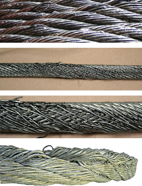
Example: Severe crown wire breaks on a 10-strand overhead crane wire rope. Crown breaks originate at the OUTSIDE of the rope at the contact point between rope and sheave/drum.
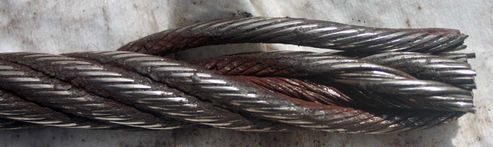
Remove the rope from service even if you find a SINGLE individual wire break which originates from inside of the rope. These so called VALLEY breaks have shown to be the cause for unexpected complete rope failures.
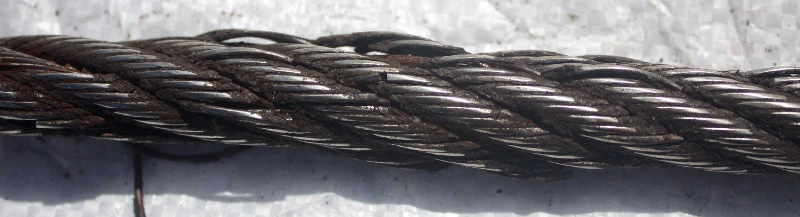
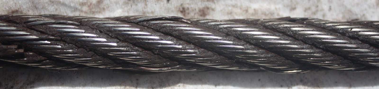
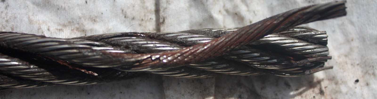
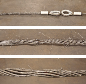
These 3 picture show what happens when you connect a left-lay rope to a right-lay rope, as done with this boom pendant extension. Both ropes are opening up to the point where the strands are nearly parallel to each other; they completely untwisted themselves and developed excessive wire breaks.
The result of such non-tensioning of the layers are looping of individual wires, completely crushed strands, total deterioration of a non-rotating rope due to gross neglect of inspection procedure.
NOTE: For a more indepth discussion on wire rope discard and inspection we suggest to attend our “Wire Rope” and “SlingMax® Rigger’s Mortis Seminar”. Call 1.800.457.9997 for details and dates.
As specialist for manufacturing quality steel wire ropes over 20 years, our company can supply strong, durable and reliable ropes that capable to minimize your downtime and maximize cost effectiveness. Decades of experience we owned make us know clearly the work you do and capable to provide professional guidance.
We select the best steel or stainless steel as raw material for wire rope manufacturing. Our products are manufactured under strict quality managements and test before they leave the factory.
Our engineers can provide professional advice about picking up optimal steel wire ropes for their application, installation guidance to ensure maximum return in their wire rope system.
If you are going to pick up steel wire ropes that suit your project perfectly, you must have an ideal about the construction about them. Our company can supply bright wire rope, galvanized wire rope, stainless steel wire rope, compacted wire rope, rotation resistant wire ropes, mining wire rope, elevator wire rope, crane wire rope and gas & oilfield wire ropes. Here are some details to solve the problem that may puzzle you whether you are browsing the web or picking up steel wire ropes.
Bright steel wire ropes mean no surface treatment is applied to the rope. Therefore, they have the lower price among these three wire ropes. Generally, they are fully lubricated to protect the rope from rust and corrosion.
Galvanized steel wire ropes feature compressed zinc coating for providing excellent corrosion resistance. With higher break strength yet lower price than stainless steel, galvanized steel wire ropes are widely used in general engineering applications such as winches and security ropes.
Stainless steel wire ropes, made of quality 304, 305, 316 steels, are the most corrosive type for marine environments and other places subjected to salt water spray. Meanwhile, bright and shiny appearance can be maintained for years rather than dull as galvanized steel wire ropes.
Steel wire ropes are composed of multiple strands of individual wires that surrounding a wire or fiber center to form a combination with excellent fatigue and abrasion resistance. These wires and strands are wound in different directions to from different lay types as follows:
Beside above lay types, alternative lay ropes which combine regular lay and lang lay together and ideal for boom hoist and winch lines, can also be supplied as your request.
Two main methods about seizing steel wire ropes in conjunction with soft or annealing wire or strands to protect cut ends of the ropes form loosening.
Any wire rope in use should be inspected on a regular basis. You have too much at stake in lives and equipment to ignore thorough examination of the rope at prescribed intervals.
The purpose of inspection is to accurately estimate the service life and strength remaining in a rope so that maximum service can be had within the limits of safety. Results of the inspection should be recorded to provide a history of rope performance on a particular job.
On most jobs wire rope must be replaced before there is any risk of failure. A rope broken in service can destroy machinery and curtail production. It can also kill.
Because of the great responsibility involved in ensuring safe rigging on equipment, the person assigned to inspect should know wire rope and its operation thoroughly. Inspections should be made periodically and before each use, and the results recorded.
When inspecting the rope, the condition of the drum, sheaves, guards, cable clamps and other end fittings should be noted. The condition of these parts affects rope wear: any defects detected should be repaired.
To ensure rope soundness between inspections, all workers should participate. The operator can be most helpful by watching the ropes under his control. If any accident involving the ropes occurs, the operator should immediately shut down his equipment and report the accident to his supervisor. The equipment should be inspected before resuming operation.
The Occupational Safety and Health Act has made periodic inspection mandatory for most wire rope applications. If you need help locating the regulations that apply to your application, please give our rigging experts a call.
The actual diameter of a wire rope is the diameter of a circumscribed circle that will enclose all the strands. It’s the largest cross-sectional measurement as shown here. You should make the measurement carefully with calipers.
The rope diameter should be measured on receipt for conformity with the specification. British Standard (B.S. 302:1987, standard steel wire rope, Part 1. Clause 5.1) allow for a tolerance of - 1% to 4 % of the nominal rope diameter.
The generally accepted method of measuring rope diameter for compliance with the standard is to use a caliper with jaws broad enough to cover not less than two adjacent stands. The measurement must be taken on a straight portion of rope at two points at least 1 meter apart. At each point two diameters at right angles should be measured. The average of the four measurement is the actual diameter.
After the rope has made the first few cycles under low load, the rope diameter should be measured at several points. The average value of all the measurements at each point must be recorded and will form the basis of comparison for all future measurements.
The measurements of the rope diameter an essential part of all inspections and examinations. It ensures the maximum diameter reduction does not exceed the recommended figure. As stated in 5.2 British standard 6570 recommends that a wire rope should be discarded when the diameter of the rope is reduced to 90% of the nominal diameter.
A comparison of the measured data with the recorded previous values can detect an abnormal rate of reduction in diameter. Coupled with assessment of previous rope examination data, the probable date of rope renewal can be predicted.
If we examine the cross-section of a six-stand wire rope, we will find that measuring the thickness of the rope over the crowns (Fig-a) will produce a higher value than measuring it over the valleys (Fig-b). The actual diameter of the rope is defined as the diameter of the circumscribing circle.
When using a conventional caliper, wire rope with an even number of outer strands (four-, six, eight-, and multi strand) ropes must be measured from crown to crown. The advantage of a proper wire rope caliper with measuring plates is that even if the measurement is carried out "incorrectly", adjacent crowns are always included, so that the actual diameter is determined at any section. (Fig-c)
Measuring the diameter of wire rope with an uneven number of outer strands (three, five, seven, or nine-strand ropes) is more complicated: a crown on the one side of the wire rope always has a valley as a counterpart on the other side of the wire rope. A conventional caliper, therefore, has to be applied diagonally to the axis of the rope, so that at any time a crown adjacent to a valley is covered. Again a wire rope caliper with measuring plate is definitely to be preferred as it always includes strands crowns.
In all cases during periodic examinations where the measurements are to be recorded, the rope should be measured as already described. Where the roundness is being checked to detect potential faults, two diameters, one at right angles to the other can be taken and noted in the records. The entry into the records might read rope diameter : 20.4/20.5mm.
After a rope has been fitted to the appliance, its length cannot be measured again accurately, with out a great deal of trouble. The purpose of measuring the length of lay is to detect any increase in the rope length which may have been caused by corrosion, core deterioration or rope rotation (unlaying). With n new rope the wire and strands should be allowed to settle into their permanent position. Six or seven lifting cycles with a light to medium load are recommended before measuring error, the measurement should be made over four lays and the length divided by four lays and the length divided by four to find the average lay length.
On eight strand ropes the eight, sixteen, twenty-four and thirty-second strands must be marked. Using a straight length of the rope and with the rope under no load, first mark any strand on the crown with a piece of chalk; this strand now become"" crown zero"". Excluding this strands, count the next eight strands and mark the eight strand with chalk. Exclude the eight strand and repeat the procedures further two times. The measured length between the outer chalk marks is then divided by four to give the lay length.
As a rough check on the overall accuracy of the chalk marking, the length of lay for eight strand ropes is approximately between 6.25 and 6.5 x the diameter of the rope e.g. using a lay length of 6.5 x rope diameter, four lay length of a 32mm diameter rope will be 32mm x 6.5 x 4=832mm.
An alternate method of measuring the rope lay is to secure the free end of the roll of adding machine paper to the rope with adhesive tape. The paper is rolled out over the rope and simultaneously the wax pencil is drawn over the paper, providing a clear print of the outer wires of the rope. The finished print can be field for comparison with later measurements.
A third method is to wrap typing carbon papers round the rope under the roll of paper. By rubbing along the paper with a piece of cardboard, the carbon marking on the underside of the paper can be confined to the tops of the strand crowns.
Wire rope is a collection of metal strands that have been twisted and wound to form the shape of a helix with the purpose of supporting and lifting heavy loads and performing tasks that are too rigorous for standard wire. On shipping docks, rigging, and load bearing equipment, wire rope is attached to swivels, shackles, or hooks to lift a load in a controlled, even, and efficient manner.
The uses for wire rope include adding support to suspension bridges, lifting elevators, and serving as additional reinforcement for towers. The design of wire rope, with its multiple strands wrapped around a stable core, provides strength, flexibility, and ease of handling for applications that have bending stress.
Individual designs of wire rope involve different materials, wire, and strand configurations as a means for supporting and assisting in the completion of lifting or supportive applications.
The term wire rope encompasses a wide range of mechanical tools that are made to perform heavy and extreme lifting jobs. Wire rope is a complicated and complex tool with multiple moving parts capable of moving in unison. A 6 by 25 wire rope has 150 outer strands that move as one in an intricate pattern supported by a flexible core.
An essential part of the design of wire rope is the required clearance between the strands to give each stand the freedom to move and adjust when the rope bends. It is this unique feature that differentiates wire rope from solid wire and other forms of cable.
The basic element of wire rope is wire that is used to configure, shape, and form the rope. Typically, steel, stainless steel, and galvanized wires are the first choice with aluminum, nickel alloy, bronze, copper, and titanium being second possibilities. The choice of wire is dependent on the type of work the wire is going to be used to perform with strength, flexibility, and abrasion resistance being the major determining factors.
Stainless steel wire rope has all of the basic qualities of galvanized and general wire rope with the added benefits of corrosion and rust resistance; this makes it the ideal choice for harsh and stressful conditions.
Steel wire rope is classified as general purpose wire rope and comes in a wide variety of sizes, diameters, and strengths. It is the most common type of wire rope and is used for several industrial, manufacturing, and construction applications.
Before going further into the discussion of how wire rope is made, it is important to understand the numbers used to describe each type. All wire ropes have a core around which wires are wound. The various styles of cores vary according to the construction and design of the requirements of the wire rope that is being produced.
Wire rope is classified by the number of strands it has as well as the number of wires in each strand. The most common classification is a seven wire rope that has one strand in the center and six around its circumference. This type of wire rope is lightweight with a very simple construction. The majority of wire ropes are more complex and intricate with multiple intertwining strands and wires.
What must be understood about wire rope is that it has a complicated configuration. It is actually wires wrapped around wires to form bundles that are wrapped around other bundles. In the case of a seven wire wire rope, the core has bundles of wires wound around it; this can be seen in the image below.
The first step in wire rope creation is the production of wire strands where wires are wound around a single core wire. The number of wires included in the strand is dependent on the specified strength, flexibility, and size requirements of the rope. Once the strand is completed, it is straightened before being moved to wire rope construction.
Like wire ropes, strands have different patterns; patterns are the arrangements of the wires and their diameters. Though most strands have a core, there are strand patterns that have three or four wires without a core that are referred to as centerless strands. The design of each strand pattern is meant to enhance the strength of the wire rope and improve its performance.
For a multiple layer strand, the layers of wire are placed over one another in successive order. The placement of the wires on top of each other must be such that they fit smoothly and evenly.
The Warrington pattern is like the multiple layer pattern with one variation. Like the multiple layer pattern, the inner wires and the core are the same and have the same diameter. The difference is in the outer layer, which has wires of alternating sizes of large and small with larger diameter wires laying in the valleys of the inner wires.
All of the wires of a filler pattern are the same size. What makes this pattern unique is the insertion of small wires in the valleys of the inner wires to fill the gap between the inner and outer layer.
The flattened strand pattern is also known as the triangular strand, which can be triangular or oval. Three round wires form the core. The outer flattened surface has a greater sectional metallic area; this makes this pattern stronger and longer lasting.
The core of a wire rope runs through the center of the rope and can be composed of a variety of materials, which include synthetic fibers, natural fibers, a single strand, or another wire rope. The core supports the wound strands, helps maintain their position, is an effective lubricant carrier, and provides support.
Wire ropes with fiber cores are restricted to light loads and are not used in severe, harsh, or stressful conditions. Polypropylene and nylon are types of synthetic fiber cores and can be used in conditions where there is exposure to chemicals.
Cores made of wire are classified as independent wire cores. The core of a wire rope with a wire core is actually a wire rope with another wire rope serving as the core, as can be seen in the diagram below. These types of wire ropes are used where the rope will be exposed to exceptional resistance and crushing.
A strand, or wire strand core, is exactly like the rest of the strands of the wire rope with wires of the same diameter and size as the other strands.
The choice of core and creation of the strands are the simplest yet most essential parts of wire rope construction. Wire rope lays, the method used to wind the strands, is more complex and involves several choices.
Lay is a term used to describe three of the main characteristics of wire rope: direction, relationship, and linear distance. The strands can be wrapped around the core going right or left. Right or left refers to the direction of the strands wrapped around the core and the wires within the strands. The linear distance is how far a strand moves when it is making a revolution around the core.
In a regular lay, the wires and strands spiral in opposite directions. With a right hand regular lay, the wires spiral to the left and the strands to the right. In the left hand regular lay, the wires spiral to the right and the strands to the left. This type of lay is easy to handle but wears out quickly because the crown wires are in contact with the bearing surface.
In the Lang, or Albert, lay, the wires and strands spiral in the same direction with right hand lay being the most common. The wires in a Lang lay appear to run parallel to the center line of the rope. The difficulty with Lang lay wire ropes is handling since they tend to kink, twist, and crush.
Wire rope is an exceptionally strong tool that has been configured and designed to withstand the stress placed upon it through rigorous and continual use. In most applications, wire rope has to endure extreme stress and strain. It is for these reasons that coatings have been developed to protect wire rope from abrasions, corrosion, UV rays, and harmful and damaging chemicals.
Three main types of coatings are used to protect wire rope: polyvinyl chloride (PVC), polypropylene, and nylon. Of the three types, PVC is the most popular.
In cases where there are severe and hazardous working conditions, polypropylene is the recommended choice since it is capable of protecting wire rope against corrosion and chemical leaching. Additionally, it is resistant to impact damage and abrasion. Polypropylene is a tough, rigid, and crystalline thermoplastic that is made from a propene monomer and is resilient as well as inexpensive.
Braided wires are electrical conductors made up of small wires that are braided together to form a round tubular braid. The braiding and configuration of braided wire makes them very sturdy such that they do not break when flexed or bent. Braided wires are widely used as conductors, are commonly made from copper due to copper"s exceptional conductivity, and can be bare or coated depending on the application.
Braided wire can be round and tubular or flat. Round tubular braids fit in most spaces where flat braided wire will not. Flat braided wire begins as round braided wire which is flattened on a capstan. They are exceptionally strong and designed for medical and aircraft applications.
Metals used to make wire rope are various grades of stainless steel, bright steel, and galvanized steel. Though the majority of wire rope manufacturers use these three metals, other metals such as copper, aluminum, bronze, and monel are also used on a limited basis.
The most important aspect of wire rope is the wire and the metal from which it is made. The strength and resilience of wire rope is highly dependent on the quality of metal used to make it, and these are essential factors to be considered when purchasing it.
Bright steel wire does not have a coating and is rotation resistant, (designed to not rotate when lifting a load). It is drawn from hot rolled rods that are put through a die to match its specific dimensional tolerances, mechanical properties, and finish. Bright wire is used as a single line in conditions that require a rope that will resist cabling.
Galvanized steel has a zinc coating for corrosion resistance and has the same strength and durability as bright steel. Environmental conditions determine the use of galvanized steel. In mildly severe and slightly harsh conditions, galvanized steel wire is an economical replacement for stainless steel.
In the manufacturing process, galvanized wire goes through the process of galvanization, a method of coating steel wire with a protective and rust resistant metal. Galvanized wire is exceptionally strong, rust resistant, and flexible enough to meet the needs of a variety of applications.
Wire rope made from copper is mostly used for electrical applications due to its exceptional electrical characteristics. The benefits of copper wire rope are its durability, flexibility, and resilience compared to standard copper wire. The strength of copper wire rope is seen in its use in applications where there are vibrations and shaking.
The wire rope lubrication process begins during its fabrication and continues during its use. Lubrication of wire rope is designed to lower the amount of friction it endures and provide corrosion protection. Continued lubrication increases the lifespan of wire rope by preventing it from drying up, rusting, and breaking.
The types of lubricants for wire rope are penetrating or coating with coatings covering and sealing the outside of the rope. Penetrating lubricants go deep into the rope and seep into the core where they evaporate to form a thick coating or film.
The application of the lubricant is dependent on the type of core. Fiber cores absorb the lubricant and serve as a reservoir that retains the lubricant for an extended period of time. With metal cores, the lubricant is applied as the wire is twisted into strands to give complete saturation and coverage of the wires.
There are several types of greases that are used as wire rope lubricating agents and are made up of oil, a thickener, and additives. The essential components are the base oil and additives, which influence the behavior of the grease. The thickener holds the base oil and additives together. The amount of base oil in a grease is between 70% and 95% with an additive of 10%.
The additive in grease enhances the positive properties of the oil and suppresses the negative properties. Common additives are oxidation and rust inhibitors as well as pressure, wear, and friction reducing agents.
Of the many choices for lubricants, vegetable oil is the easiest to use and penetrates the deepest. The design of the additives for vegetable oils gives them the necessary qualities required to penetrate deep into a wire rope. The exceptional penetration provides protection against wear and corrosion. Since vegetable oil is a fluid, it helps in washing the wire rope to remove external abrasive contaminants.
Wire rope is widely used in machines, structures, and varied lifting applications. Its type, size, and requirements are determined by how it will be used. Regardless of its use, wire rope guarantees exceptional strength and provides high quality and excellent performance.
The lifting of heavy loads for centuries involved the use of hemp rope or chains, neither of which was a guaranteed or substantial method. Early in the 18th Century, between 1824 and 1838, Wilhelm Albert, a German mining engineer, combined the twisting of hemp and strength of chains to create today‘s wire rope.
The most common use of wire rope is as a part of a crane hoist wherein it is attached to the hook of the hoist and wrapped around a grooved drum. The tensile strength and durability of wire rope makes an ideal tool for lifting and keeping loads secure. Though it is used in several industries, it is very popular for production environments wherein materials need to be lifted quickly and efficiently.
In addition to its many lifting applications, the strength and stability of wire rope is useful in other applications, especially in the aerospace industry. Pedals, levers, and connectors in the cockpit of an aircraft are connected with wire rope. The wires provide for the passage of power between systems and mechanisms; this allows control of the aircraft. Wire rope is used to control propeller pitch, cowl flaps, and the throttle. It also assists in lowering and minimizing vibrations.
Tires are reinforced with wire rope to increase their durability and strength. All automotive production environments make use of wire ropes for supplying materials, moving heaving loads, and positioning equipment. Wire rope can be found in the production of steering wheels, cables, exhausts, springs, sunroofs, doors, and seating components.
As surprising as it may seem, the place that wire rope has the greatest use is in the home, where its strength, long life, endurance, and resilience provide guaranteed protection and performance. The main reason wire ropes are so popular for home use is cost.
Inexpensive, easy to obtain, easy to install, and easy to maintain, wire ropes provide an additional method for performing home repairs and structural support. Their excellent flexibility and sturdiness combined with their invisibility has made wire rope an ideal solution to several home maintenance issues. It is used to support staircases, fences, decks, and hang plants.
The search and production of crude oil has relied on wire ropes for centuries to lift drill bits, insert shafts, and support oil rigs on land and the water. When equipment, machinery, and tools have to be lowered into the depths of the earth and sea, wire ropes are the tool that the oil industry relies on to do the job.
Many of the tasks of oil production require tools that are capable of enduring severe and harsh conditions. Wire ropes have to withstand enormous pressure, extraordinary stress, and a wide range of temperatures. The use of wire rope includes maintaining oil rig stability and moorings for offshore rigs.
Wire rope has long been a standard component for the transportation industry, from the cable cars of San Francisco to the lift chairs for ski resorts. For many years, cable cars have relied on heavy duty cables (wire ropes) to be pulled by a central motor from multiple locations. It is a method of transportation that has existed for centuries.
In Europe, funiculars use cables that hang from a support to move cars up and down a mountain with cables moving in opposite directions. The word funicular is from the French word funiculaire, meaning railway by cable. The terms wire rope and cable are used interchangeably when discussed by professionals. The first part of funicular, or funiculaire, is from the Latin word "funis," meaning rope.
The major use for wire ropes in the food and beverage industries is as a means for lifting and moving heavy loads. Wine barrels and containers full of ingredients are lifted and placed through use of cranes and wire ropes. They are also part of conveyor systems that move products from one station to another.
From the beginnings of amusement rides up to the present, wire ropes have been an essential part of attraction construction and safety. They pull cars on roller coasters, hold cabins that swing, and move carriages through haunted houses. The main concern of amusement parks is safety. The strength, stability, and guaranteed performance of wire ropes ensures that people who attend amusement parks will have a good time and stay safe.
The rigging used to complete the stunts in modern movies depends on wire rope for safety. Much like in amusement rides, wire ropes protect performers from injury and harm as they hang above a scene or carry out an impossible move.
The live theater industry uses wire ropes to raise and lower curtains, support overhead rigging, and hold backdrops and scenery pieces. During a production, rapid and efficient movement is a necessity that is facilitated by the use of wire ropes.
Wire rope is a tool that we tend to envision as indestructible, unable to succumb to any form of damage. Though it is exceptionally sturdy and strong as well as capable of enduring constant use, it is just as susceptible to breakdown as any other tool.
To avoid serious harm and damage, wire ropes should be scheduled for regular inspections. There are situations that can damage or break a wire rope; these should be understood prior to the problem arising.
Guide rollers have the potential to damage and cause abrasions on wire rope if they become rough and uneven. Of the various elements of a crane and lift, guide rollers have the greatest contact with the mechanism‘s wire rope. Regular inspection of guide rollers will ensure they are not damaging the rope or causing abrasions.
Bending is normally a regular part of wire rope usage; this occurs repetitively as the rope passes through a sheave. As a wire rope traverses the sheave, it is continually bent and develops cracks or breaks. The cracking and breaking are exacerbated by movement on and off the groove of the drum. Normally, the breakage happens on the surface and is visible. Once it appears, it accelerates to the core of the rope.
A bird cage is caused by a sudden release of tension and a rebound of the rope. This type of break requires that the rope be replaced since the place of the break will not return to its normal condition.
Wire ropes are multi-layered; this makes them flexible and torque balanced. The layering inside and outside creates flexibility and wear resistance. Relative motion between the wires causes wear over time, which leads to internal breakage. The detection of these breaks can be indicated by an electromagnetic inspection that calculates the diameter of the rope.
Kinked wire rope is caused by pulling a loop on a slack line during installation or operation; this causes a distortion in the strands and wires. This is a serious condition that necessitates rope replacement.
Corrosion damage is the most difficult cause of wire rope damage to identify, which makes it the most dangerous. The main reason for corrosion is poor lubrication that can be seen in the pitted surface of the rope.
The types of damage and problems listed here are only a small portion of the problems that can be caused if a wire rope is not regularly lubricated and inspected. Various regulatory agencies require that wire ropes be inspected weekly or monthly and provide a list of factors to examine.
As with any type of heavy duty equipment, wire rope is required to adhere to a set of regulations or standards that monitor and control its use for safety and quality reasons. The two organizations that provide guidelines for wire rope use are the American Society of Mechanical Engineers (ASME) and the Occupational Safety and Health Administration (OSHA).
All wire rope manufacturers and users closely follow the standards and guidelines established by OSHA and ASME. In the majority of cases, they will identify the specific standards they are following in regard to their products.
OSHA‘s regulations regarding wire rope fall under sections 1910, 1915, and 1926, with the majority of the stipulations listed in 1926 under material handling, storage, use, and disposal.
"Running rope in service shall be visually inspected daily, unless a qualified person determines it should be performed more frequently. The visual inspection shall consist of observation of all rope that can reasonably be expected to be in use during the day‘s operations. The inspector should focus on discovering gross damage that may be an immediate hazard."
"The inspection frequency shall be based on such factors as rope life on the particular installation or similar installations, severity of environment, percentage of capacity lifts, frequency rates of operation, and exposure to shock loads. Inspections need not be at equal calendar intervals and should be more frequent as the rope approaches the end of its useful life. Close visual inspection of the entire rope length shall be made to evaluate inspection and removal criteria."
ASTM A1023 covers the requirements for steel wire ropes with specifications for various grades and constructions from ¼ in. (6 mm) to 31/2 in. (89 mm) manufactured from uncoated or metallic coated wire. Included are cord products from 1/32 in. (0.8 mm) to 3/8 in. (10 mm) made from metallic coated wire.
United States Federal Spec RR W 410 covers wire ropes and wire seizing strands but does not include all types, classes, constructions, and sizes of wire rope and strands that are available. The purpose of Spec RR W 410 is to cover more common types, classes, constructions, and sizes suitable for federal government use.
Wire rope and wire seizing strand covered by United States Federal Spec RR W 410 are intended for use in general hauling, hoisting, lifting, transporting, well drilling, in passenger and freight elevators, and for marine mooring, towing, trawling, and similar work, none of which are for use with aircraft.
API 9A lists the minimum standards required for use of wire rope for the petroleum and natural gas industries. The types of applications include tubing lines, rod hanger lines, sand lines, cable-tool drilling and clean out lines, cable tool casing lines, rotary drilling lines, winch lines, horse head pumping unit lines, torpedo lines, mast-raising lines, guideline tensioner lines, riser tensioner lines, and mooring and anchor lines. Well serving wire ropes such as lifting slings and well measuring are also included in API 9A.
Wire rope is a collection of metal strands that have been twisted and wound to form the shape of a helix with the purpose of supporting and lifting heavy loads and performing tasks that are too rigorous for standard wire.
Individual designs of wire rope involve different materials, wire, and strand configurations as a means for supporting and assisting in the completion of a lifting or supportive task.
In stricter senses, the term wire rope refers to a diameter larger than 9.5 mm (3⁄8 in), with smaller gauges designated cable or cords.wrought iron wires were used, but today steel is the main material used for wire ropes.
Historically, wire rope evolved from wrought iron chains, which had a record of mechanical failure. While flaws in chain links or solid steel bars can lead to catastrophic failure, flaws in the wires making up a steel cable are less critical as the other wires easily take up the load. While friction between the individual wires and strands causes wear over the life of the rope, it also helps to compensate for minor failures in the short run.
Wire ropes were developed starting with mining hoist applications in the 1830s. Wire ropes are used dynamically for lifting and hoisting in cranes and elevators, and for transmission of mechanical power. Wire rope is also used to transmit force in mechanisms, such as a Bowden cable or the control surfaces of an airplane connected to levers and pedals in the cockpit. Only aircraft cables have WSC (wire strand core). Also, aircraft cables are available in smaller diameters than wire rope. For example, aircraft cables are available in 1.2 mm (3⁄64 in) diameter while most wire ropes begin at a 6.4 mm (1⁄4 in) diameter.suspension bridges or as guy wires to support towers. An aerial tramway relies on wire rope to support and move cargo overhead.
Modern wire rope was invented by the German mining engineer Wilhelm Albert in the years between 1831 and 1834 for use in mining in the Harz Mountains in Clausthal, Lower Saxony, Germany.chains, such as had been used before.
Wilhelm Albert"s first ropes consisted of three strands consisting of four wires each. In 1840, Scotsman Robert Stirling Newall improved the process further.John A. Roebling, starting in 1841suspension bridge building. Roebling introduced a number of innovations in the design, materials and manufacture of wire rope. Ever with an ear to technology developments in mining and railroading, Josiah White and Erskine Hazard, principal ownersLehigh Coal & Navigation Company (LC&N Co.) — as they had with the first blast furnaces in the Lehigh Valley — built a Wire Rope factory in Mauch Chunk,Pennsylvania in 1848, which provided lift cables for the Ashley Planes project, then the back track planes of the Summit Hill & Mauch Chunk Railroad, improving its attractiveness as a premier tourism destination, and vastly improving the throughput of the coal capacity since return of cars dropped from nearly four hours to less than 20 minutes. The decades were witness to a burgeoning increase in deep shaft mining in both Europe and North America as surface mineral deposits were exhausted and miners had to chase layers along inclined layers. The era was early in railroad development and steam engines lacked sufficient tractive effort to climb steep slopes, so incline plane railways were common. This pushed development of cable hoists rapidly in the United States as surface deposits in the Anthracite Coal Region north and south dove deeper every year, and even the rich deposits in the Panther Creek Valley required LC&N Co. to drive their first shafts into lower slopes beginning Lansford and its Schuylkill County twin-town Coaldale.
The German engineering firm of Adolf Bleichert & Co. was founded in 1874 and began to build bicable aerial tramways for mining in the Ruhr Valley. With important patents, and dozens of working systems in Europe, Bleichert dominated the global industry, later licensing its designs and manufacturing techniques to Trenton Iron Works, New Jersey, USA which built systems across America. Adolf Bleichert & Co. went on to build hundreds of aerial tramways around the world: from Alaska to Argentina, Australia and Spitsbergen. The Bleichert company also built hundreds of aerial tramways for both the Imperial German Army and the Wehrmacht.
In the last half of the 19th century, wire rope systems were used as a means of transmitting mechanical powercable cars. Wire rope systems cost one-tenth as much and had lower friction losses than line shafts. Because of these advantages, wire rope systems were used to transmit power for a distance of a few miles or kilometers.
Steel wires for wire ropes are normally made of non-alloy carbon steel with a carbon content of 0.4 to 0.95%. The very high strength of the rope wires enables wire ropes to support large tensile forces and to run over sheaves with relatively small diameters.
In the mostly used parallel lay strands, the lay length of all the wire layers is equal and the wires of any two superimposed layers are parallel, resulting in linear contact. The wire of the outer layer is supported by two wires of the inner layer. These wires are neighbors along the whole length of the strand. Parallel lay strands are made in one operation. The endurance of wire ropes with this kind of strand is always much greater than of those (seldom used) with cross lay strands. Parallel lay strands with two wire layers have the construction Filler, Seale or Warrington.
In principle, spiral ropes are round strands as they have an assembly of layers of wires laid helically over a centre with at least one layer of wires being laid in the opposite direction to that of the outer layer. Spiral ropes can be dimensioned in such a way that they are non-rotating which means that under tension the rope torque is nearly zero. The open spiral rope consists only of round wires. The half-locked coil rope and the full-locked coil rope always have a centre made of round wires. The locked coil ropes have one or more outer layers of profile wires. They have the advantage that their construction prevents the penetration of dirt and water to a greater extent and it also protects them from loss of lubricant. In addition, they have one further very important advantage as the ends of a broken outer wire cannot leave the rope if it has the proper dimensions.
Stranded ropes are an assembly of several strands laid helically in one or more layers around a core. This core can be one of three types. The first is a fiber core, made up of synthetic material or natural fibers like sisal. Synthetic fibers are stronger and more uniform but cannot absorb much lubricant. Natural fibers can absorb up to 15% of their weight in lubricant and so protect the inner wires much better from corrosion than synthetic fibers do. Fiber cores are the most flexible and elastic, but have the downside of getting crushed easily. The second type, wire strand core, is made up of one additional strand of wire, and is typically used for suspension. The third type is independent wire rope core (IWRC), which is the most durable in all types of environments.ordinary lay rope if the lay direction of the wires in the outer strands is in the opposite direction to the lay of the outer strands themselves. If both the wires in the outer strands and the outer strands themselves have the same lay direction, the rope is called a lang lay rope (from Dutch langslag contrary to kruisslag,Regular lay means the individual wires were wrapped around the centers in one direction and the strands were wrapped around the core in the opposite direction.
Multi-strand ropes are all more or less resistant to rotation and have at least two layers of strands laid helically around a centre. The direction of the outer strands is opposite to that of the underlying strand layers. Ropes with three strand layers can be nearly non-rotating. Ropes with two strand layers are mostly only low-rotating.
Stationary ropes, stay ropes (spiral ropes, mostly full-locked) have to carry tensile forces and are therefore mainly loaded by static and fluctuating tensile stresses. Ropes used for suspension are often called cables.
Track ropes (full locked ropes) have to act as rails for the rollers of cabins or other loads in aerial ropeways and cable cranes. In contrast to running ropes, track ropes do not take on the curvature of the rollers. Under the roller force, a so-called free bending radius of the rope occurs. This radius increases (and the bending stresses decrease) with the tensile force and decreases with the roller force.
Wire rope slings (stranded ropes) are used to harness various kinds of goods. These slings are stressed by the tensile forces but first of all by bending stresses when bent over the more or less sharp edges of the goods.
Technical regulations apply to the design of rope drives for cranes, elevators, rope ways and mining installations. Factors that are considered in design include:
Donandt force (yielding tensile force for a given bending diameter ratio D/d) - strict limit. The nominal rope tensile force S must be smaller than the Donandt force SD1.
The wire ropes are stressed by fluctuating forces, by wear, by corrosion and in seldom cases by extreme forces. The rope life is finite and the safety is only ensured by inspection for the detection of wire breaks on a reference rope length, of cross-section loss, as well as other failures so that the wire rope can be replaced before a dangerous situation occurs. Installations should be designed to facilitate the inspection of the wire ropes.
Lifting installations for passenger transportation require that a combination of several methods should be used to prevent a car from plunging downwards. Elevators must have redundant bearing ropes and a safety gear. Ropeways and mine hoistings must be permanently supervised by a responsible manager and the rope must be inspected by a magnetic method capable of detecting inner wire breaks.
The end of a wire rope tends to fray readily, and cannot be easily connected to plant and equipment. There are different ways of securing the ends of wire ropes to prevent fraying. The common and useful type of end fitting for a wire rope is to turn the end back to form a loop. The loose end is then fixed back on the wire rope. Termination efficiencies vary from about 70% for a Flemish eye alone; to nearly 90% for a Flemish eye and splice; to 100% for potted ends and swagings.
When the wire rope is terminated with a loop, there is a risk that it will bend too tightly, especially when the loop is connected to a device that concentrates the load on a relatively small area. A thimble can be installed inside the loop to preserve the natural shape of the loop, and protect the cable from pinching and abrading on the inside of the loop. The use of thimbles in loops is industry best practice. The thimble prevents the load from coming into direct contact with the wires.
A wire rope clip, sometimes called a clamp, is used to fix the loose end of the loop back to the wire rope. It usually consists of a U-bolt, a forged saddle, and two nuts. The two layers of wire rope are placed in the U-bolt. The saddle is then fitted to the bolt over the ropes (the saddle includes two holes to fit to the U-bolt). The nuts secure the arrangement in place. Two or more clips are usually used to terminate a wire rope depending on the diameter. As many as eight may be needed for a 2 in (50.8 mm) diameter rope.
The mnemonic "never saddle a dead horse" means that when installing clips, the saddle portion of the assembly is placed on the load-bearing or "live" side, not on the non-load-bearing or "dead" side of the cable. This is to protect the live or stress-bearing end of the rope against crushing and abuse. The flat bearing seat and extended prongs of the body are designed to protect the rope and are always placed against the live end.
An eye splice may be used to terminate the loose end of a wire rope when forming a loop. The strands of the end of a wire rope are unwound a certain distance, then bent around so that the end of the unwrapped length forms an eye. The unwrapped strands are then plaited back into the wire rope, forming the loop, or an eye, called an eye splice.
A Flemish eye, or Dutch Splice, involves unwrapping three strands (the strands need to be next to each other, not alternates) of the wire and keeping them off to one side. The remaining strands are bent around, until the end of the wire meets the "V" where the unwrapping finished, to form the eye. The strands kept to one side are now re-wrapped by wrapping from the end of the wire back to the "V" of the eye. These strands are effectively rewrapped along the wire in the opposite direction to their original lay. When this type of rope splice is used specifically on wire rope, it is called a "Molly Hogan", and, by some, a "Dutch" eye instead of a "Flemish" eye.
Swaging is a method of wire rope termination that refers to the installation technique. The purpose of swaging wire rope fittings is to connect two wire rope ends together, or to otherwise terminate one end of wire rope to something else. A mechanical or hydraulic swager is used to compress and deform the fitting, creating a permanent connection. Threaded studs, ferrules, sockets, and sleeves are examples of different swaged terminations.
A wedge socket termination is useful when the fitting needs to be replaced frequently. For example, if the end of a wire rope is in a high-wear region, the rope may be periodically trimmed, requiring the termination hardware to be removed and reapplied. An example of this is on the ends of the drag ropes on a dragline. The end loop of the wire rope enters a tapered opening in the socket, wrapped around a separate component called the wedge. The arrangement is knocked in place, and load gradually eased onto the rope. As the load increases on the wire rope, the wedge become more secure, gripping the rope tighter.
Poured sockets are used to make a high strength, permanent termination; they are created by inserting the wire rope into the narrow end of a conical cavity which is oriented in-line with the intended direction of strain. The individual wires are splayed out inside the cone or "capel", and the cone is then filled with molten lead-antimony-tin (Pb80Sb15Sn5) solder or "white metal capping",zincpolyester resin compound.
Donald Sayenga. "Modern History of Wire Rope". History of the Atlantic Cable & Submarine Telegraphy (atlantic-cable.com). Archived from the original on 3 February 2014. Retrieved 9 April 2014.


 8613371530291