
valley breaks wire rope pricelist
Example: Severe crown wire breaks on a 10-strand overhead crane wire rope. Crown breaks originate at the OUTSIDE of the rope at the contact point between rope and sheave/drum.
Remove the rope from service even if you find a SINGLE individual wire break which originates from inside of the rope. These so called VALLEY breaks have shown to be the cause for unexpected complete rope failures.
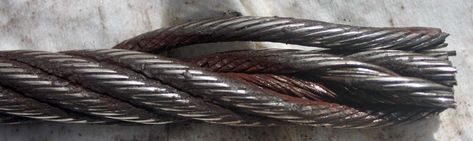
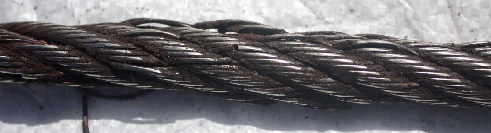
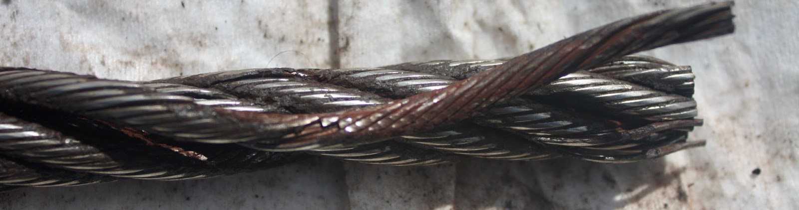
These 3 picture show what happens when you connect a left-lay rope to a right-lay rope, as done with this boom pendant extension. Both ropes are opening up to the point where the strands are nearly parallel to each other; they completely untwisted themselves and developed excessive wire breaks.
The result of such non-tensioning of the layers are looping of individual wires, completely crushed strands, total deterioration of a non-rotating rope due to gross neglect of inspection procedure.
NOTE: For a more indepth discussion on wire rope discard and inspection we suggest to attend our “Wire Rope” and “SlingMax® Rigger’s Mortis Seminar”. Call 1.800.457.9997 for details and dates.
The actual diameter of a wire rope is the diameter of a circumscribed circle that will enclose all the strands. It’s the largest cross-sectional measurement as shown here. You should make the measurement carefully with calipers.
The rope diameter should be measured on receipt for conformity with the specification. British Standard (B.S. 302:1987, standard steel wire rope, Part 1. Clause 5.1) allow for a tolerance of - 1% to 4 % of the nominal rope diameter.
The generally accepted method of measuring rope diameter for compliance with the standard is to use a caliper with jaws broad enough to cover not less than two adjacent stands. The measurement must be taken on a straight portion of rope at two points at least 1 meter apart. At each point two diameters at right angles should be measured. The average of the four measurement is the actual diameter.
After the rope has made the first few cycles under low load, the rope diameter should be measured at several points. The average value of all the measurements at each point must be recorded and will form the basis of comparison for all future measurements.
The measurements of the rope diameter an essential part of all inspections and examinations. It ensures the maximum diameter reduction does not exceed the recommended figure. As stated in 5.2 British standard 6570 recommends that a wire rope should be discarded when the diameter of the rope is reduced to 90% of the nominal diameter.
A comparison of the measured data with the recorded previous values can detect an abnormal rate of reduction in diameter. Coupled with assessment of previous rope examination data, the probable date of rope renewal can be predicted.
If we examine the cross-section of a six-stand wire rope, we will find that measuring the thickness of the rope over the crowns (Fig-a) will produce a higher value than measuring it over the valleys (Fig-b). The actual diameter of the rope is defined as the diameter of the circumscribing circle.
When using a conventional caliper, wire rope with an even number of outer strands (four-, six, eight-, and multi strand) ropes must be measured from crown to crown. The advantage of a proper wire rope caliper with measuring plates is that even if the measurement is carried out "incorrectly", adjacent crowns are always included, so that the actual diameter is determined at any section. (Fig-c)
Measuring the diameter of wire rope with an uneven number of outer strands (three, five, seven, or nine-strand ropes) is more complicated: a crown on the one side of the wire rope always has a valley as a counterpart on the other side of the wire rope. A conventional caliper, therefore, has to be applied diagonally to the axis of the rope, so that at any time a crown adjacent to a valley is covered. Again a wire rope caliper with measuring plate is definitely to be preferred as it always includes strands crowns.
In all cases during periodic examinations where the measurements are to be recorded, the rope should be measured as already described. Where the roundness is being checked to detect potential faults, two diameters, one at right angles to the other can be taken and noted in the records. The entry into the records might read rope diameter : 20.4/20.5mm.
After a rope has been fitted to the appliance, its length cannot be measured again accurately, with out a great deal of trouble. The purpose of measuring the length of lay is to detect any increase in the rope length which may have been caused by corrosion, core deterioration or rope rotation (unlaying). With n new rope the wire and strands should be allowed to settle into their permanent position. Six or seven lifting cycles with a light to medium load are recommended before measuring error, the measurement should be made over four lays and the length divided by four lays and the length divided by four to find the average lay length.
On eight strand ropes the eight, sixteen, twenty-four and thirty-second strands must be marked. Using a straight length of the rope and with the rope under no load, first mark any strand on the crown with a piece of chalk; this strand now become"" crown zero"". Excluding this strands, count the next eight strands and mark the eight strand with chalk. Exclude the eight strand and repeat the procedures further two times. The measured length between the outer chalk marks is then divided by four to give the lay length.
As a rough check on the overall accuracy of the chalk marking, the length of lay for eight strand ropes is approximately between 6.25 and 6.5 x the diameter of the rope e.g. using a lay length of 6.5 x rope diameter, four lay length of a 32mm diameter rope will be 32mm x 6.5 x 4=832mm.
An alternate method of measuring the rope lay is to secure the free end of the roll of adding machine paper to the rope with adhesive tape. The paper is rolled out over the rope and simultaneously the wax pencil is drawn over the paper, providing a clear print of the outer wires of the rope. The finished print can be field for comparison with later measurements.
A third method is to wrap typing carbon papers round the rope under the roll of paper. By rubbing along the paper with a piece of cardboard, the carbon marking on the underside of the paper can be confined to the tops of the strand crowns.
Like all industrial equipment, aircraft cables and wire ropes wear while in service, and will require replacement. Though the cycle life of each cable varies based on construction and application, factors such as load and pulley condition can actually reduce this lifespan by triggering wire breaks. Not all wire breaks look the same, and understanding these differences can help detect issues in your system before they damage additional cables, or put human lives in danger. Here is a quick guide to help you understand where wire breaks occur (crowns vs. valleys), and three common examples of wire breaks (tension, fatigue, and abrasion).
Wire breaks typically occur in two different locations on the outside of wire rope or aircraft cable. The first location is on the crowns of the strands, which are the highest points with the most surface area exposure. The second location is the valleys, or the spaces between the strands. Though crown breaks typically result from normal wear and tear, valley breaks are more suspicious and may indicate issues with the pulley system or wire rope itself.
Wires that have been worn to a knife-edge thinness are characteristic of abrasion breaks. Abrasion can occur from a number of different sources, but sheaves are the most common. Remember to check sheaves for signs of wear, damage, or deformity and replace as necessary.
If you notice one end of a broken wire is cupped, and the other end resembles a cone, your wire rope likely experienced a tension break. Tension breaks result from excessive loading, causing the wires to stretch beyond their limits until they snap. Once one wire break appears, others will continue to occur if the cable is not addressed.
Fatigue damage is usually represented by zig-zag breaks with square ends. Like abrasion breaks, fatigue breaks can be triggered by a broad range of factors, including incorrect pulley size and excessive vibration. Check for worn pulleys and slack in the system to prevent issues from exacerbating.
Once you have replaced your damaged pulleys, or removed sharp obstructions in your system, begin your quote for brand new wire rope at https://strandcore.com/contact/. Our wire rope craftsmen can help you select the ideal wire rope for your application, and oftentimes provide a better solution for your existing setup. Browse our selection ofwire rope and aircraft cableonline, and do not hesitate to contact our sales team at sales@sanlo.com if you have any questions.
Rope Services Direct supplies a variety of anti-spin non rotating wire rope (also called rotation resistant wire-rope). All standard rope wirehas a tendency to develop torque and therefore prone to rotation, whereas non-rotating wire ropes are designed so that the wire-rope outer rotational force naturally counteracts the inner strands rotational force. This is in the event that a rope is subjected to a load.
Rope elongation and rotation occurs on standard ropes when loaded, which can therefore spin the load, quite possibly out of control, which can be dangerous. When the rope rotates in this way the strands will begin to unravel. This causes the rope to lose strength and will undoubtedly fail, which could be catastrophic. It is for these reasons that non rotating wire rope is commonly used for many types of lifting applications including main hoist rope, whip rope,crane rope, off-shore and deck rope and more.
Non rotating wire rope or rotation resistant wire rope has a different construction to standard. as wires and strands are not laid in the same direction like they would be on standard rope. Inner and outer strands of wires are laid in opposite directions. For example the inner may be constructed in left hand lay whilst the outer layer is in right hand lay. The nature of this construction means that torsional forces on the inner and outer wires/strands will counteract each other and therefore minimising the risk of unraveling.
It is worth noting that the number of strand layers will have an effect of the resistance of rotation. A 2 layer rope has less resistance than a 3 layer rope. Therefore the more layers the rope has the greater rotation resistance it will have.
These types of ropes can be classified as spin resistant, rotation resistant or non rotation resistant. Classed on the basis of the number of rotations a certain length of rope does when a force of 20% of the MBF is applied; with 1 turn or less the rope will be classified as non rotating; with rotations between 1 & 4 the rope is classed as low rotation and for rotations between 4 & 10 the rope will be classified as spin resistant, any higher and the rope is NOT rotation resistant at all.
Correct usage and care with handling will prolong the working life. This is due to the friction on the inner wires caused by the strand crossover’s which will eventually cause the inner wires to break up. This is more apparent on non rotating wire rope with two layers. Ropes with 3 or more strand layers will distribute the radial pressures more evenly. Which will reduce friction and stress on the inner wires.
Regular,thorough inspectionsof non rotating rope are essential due to the fact that it is the inner strands that often break first and broken internal wires often go unnoticed as they are difficult to see.Rope Services Direct offer inspectionson all rope with certification issued on completion.
Holding both ends of the rope will prevent unraveling. Correctly fitted terminations will help to prevent damage. Kinking and unraveling may occur and they can also have an effect on the rotational balance if not fitted correctly.


 8613371530291