
what is the minimum bending radius of wire rope made in china
This website is using a security service to protect itself from online attacks. The action you just performed triggered the security solution. There are several actions that could trigger this block including submitting a certain word or phrase, a SQL command or malformed data.
For the smaller sizes of ropes (below 12 mm) open thimble can be acceptable, but it has to be seized to the rope. In general we recommend using stainless tube thimbles and preferably with a gusset, which prevents the thimble from deformation.
Dyneema® is produced by DSM in the Netherlands. It is an ultra high molecular weight polyethylene (UHMWPE) or for short HMPE. It is superior to many other synthetic fibres in terms of weight, abrasion resistance, strength etc. Read more about HMPE/Dyneema® here.
To obtain reasonable service life from your aircraft cable or wire rope, you must choose the optimal diameter of rope and sheave for your application. In general, the larger the size of the drum or pulley with respect to the wire diameter, the longer the service life. The opposite is also true: in general, the smaller the size of the drum or pulley with respect to your wire rope, the shorter the service life. Keep these relationships between cable, rope, and pulleys in mind when specifying the competence you use in your application.
The tables below provide the minimum recommended pulley diameter as well as the approximate bend radius of the rope. You"ll notice that the calculation is approximately half of the minimum recommended pulley tread diameter. Whether running fully over the sheave or drum, or some fraction thereof, check your design against the recommendations to better understand the service life you can expect in relation to the other factors involved.

Legal status (The legal status is an assumption and is not a legal conclusion. Google has not performed a legal analysis and makes no representation as to the accuracy of the status listed.)
Current Assignee (The listed assignees may be inaccurate. Google has not performed a legal analysis and makes no representation or warranty as to the accuracy of the list.)
Priority date (The priority date is an assumption and is not a legal conclusion. Google has not performed a legal analysis and makes no representation as to the accuracy of the date listed.)
Application filed by State Grid Corp of China SGCC, State Grid Fujian Electric Power Co Ltd, Quanzhou Power Supply Co of State Grid Fujian Electric Power Co Ltd
The invention discloses a cable bending radius controller and a cable bending method. The cable bending radius controller comprises a support rod, a bendable rod, pull ropes and regulating rods, wherein one end part of the support rod is provided with a through hole with an axial line vertical to the axial line of the support rod, scale values are distributed on the support rod along the axial line of the support rod, two sides of the support rod on the scale value are provided with connecting devices, two end parts of the bendable rod are provided with connecting devices for hanging and tensioning, one end of the pull ropes or regulating rods is respectively connected to two ends of the bendable rod, the other ends of the two pull ropes are respectively connected to the connecting device on the scale value of the support rod, and the length of the pull ropes of the regulating rods between the bendable rod and the support rod is equal to the length of the support rod between the corresponding scale value and the bendable rod of the support rod. According to the controller and the cable bending method provided by the invention, the bending radius of the cable can be controlled accurately, and the problem of laying installing quality control of the cable can be effectively solved.
Along with deepening continuously of city cable, each department power grid cables quantity grows with each passing day, and cable occupies leading position in electrical network, the whether safe of its operation will directly affect the safe and stable operation of electrical network, so improving cable work quality too impatient to wait, is the emphasis in engineering construction from now on.Cable Bending Radius is cable laying construction and the important indicator ensureing its insulation property in running, if cable bending radius in cable laying operation or operation is less than setting, can directly cause its structural damage, directly affect its life-span, finally cause insulation breakdown, lead to safe mass accident, affect power network safety operation.
1. due to the reason such as urban planning and left over by history, the cable work well size in many places is general less, how reasonable Arrangement cable position control cables minimum bending radius, is a great problem in engineering construction.
2. due to all factors, the construction of present cable work is accepted by cooperation troop, because cooperation personnel professional qualities are high and the reason such as to order about by economic interests, engineering construction is caused to be all often only say progress, do not stress quality, also much safe mass hidden danger is just caused, such as: arbitrarily put cable, the hard cable that squeezes enters work well, causes the Cable Bending Radius reserved in work well to meet the demands.
3. the key factor of cable running safety is the good degree of its insulation and the uniformity of internal electric field distribution.Cable Bending Radius is the important indicator ensureing its insulation property, and too small bending radius, destroys its internal structure, directly affects its life-span, and severe patient directly will cause insulation breakdown, leads to safe mass accident.
4. traditional measurement cable minimum bending radius method is all with range estimation or tape measure etc., and the error that this method is brought is comparatively large, easily causes erroneous judgement, misjudgement, does not possess science, and do not possess practicality in construction process.
The object of the invention is to overcome the deficiencies in the prior art part, and provide a kind of structure simple, easy to use, the Cable Bending Radius controller that control cables minimum bending radius at any time can meet the demands can be guaranteed.
A kind of Cable Bending Radius controller, its structural feature is: include support bar, bendable rod and stay cord or adjusting rod, the through hole passed for bendable rod is provided with in an end of support bar, the axes normal of described through hole is in the axis of support bar, axis along support bar on support bar is distributed with scale value, the support bar both sides place at scale value place is provided with the jockey for connecting stay cord or adjusting rod, the jockey for hanging stretching is provided with at the both ends of bendable rod, operationally one end of two stay cords or adjusting rod is connected to the jockey place at bendable rod two ends, the other end of two stay cords or adjusting rod is connected to the jockey place in the identical graduation value of support bar, the pulling rope length between bendable rod to support bar after connecting equal this corresponding scale value of support bar to support bar bendable rod between length.
Cable Bending Radius controller of the present invention, in use, the minimum bending radius required for cable bending as required selects the stay cord on Cable Bending Radius controller or adjusting rod required corresponding scale value on support bar, then one end of stay cord or adjusting rod is connected to the jockey place at scale value place, the other end is connected to the jockey place at variable curved bar two ends after the length ensureing the support bar between jockey that jockey that stay cord or adjusting rod are in this scale value place of support bar and the length between bendable rod are equal to support bar corresponding scale value place to bendable rod, the radian then utilizing bendable rod and the cable bent contrast, just can see that bent cable institute is no very clearly and reach minimum sandards requirement.
Jockey for connecting stay cord or adjusting rod on described support bar is hook or draw ring, and stay cord is tied on hook or draw ring, and adjusting rod then utilizes the through hole or hook that arrange or draw ring to connect on hook or draw ring thereon.
Described variable curved bar both ends are draw ring or hook or through hole for hanging the jockey of stay cord or adjusting rod, and stay cord is tied on hook or draw ring, and adjusting rod then utilizes the through hole or hook that arrange or draw ring to connect on hook or draw ring thereon.
Cable bend method of the present invention, first the as required bending minimum bending radius required for cable selects the stay cord on Cable Bending Radius controller or adjusting rod required corresponding scale value on support bar, then one end of stay cord or adjusting rod is connected to the jockey place at scale value place, the other end is ensureing that stay cord or adjusting rod are in the jockey place connected when the draw ring at this scale value place of support bar or the length between hook to bendable rod are equal to the draw ring at the corresponding scale value place of support bar or hook into the length of the support bar between bendable rod in bendable rod end, the radian then utilizing bendable rod and the cable bent contrast, just can see that bent cable institute is no very clearly and reach minimum sandards requirement.
Cable Bending Radius controller of the present invention and cable bend method, effectively can solve cable laying fixing quality control problem, it shows:
(1) with cable controller, cable minimum bending radius is controlled, make cable insulation not impaired, extend cable service life, improve power network safety operation, also reduce power grid construction investment simultaneously.
(2) by this controller of long period mandatory requirement site operation librarian use, cable construction personnel specification construction custom can be cultivated, promote cable work quality from source.
(3) cable minimum bending radius traditional measurement method in work progress is range estimation, otherwise, can must measure after cable is in place, and this device while not affecting construction, can control bending radius.
(4) this device uses simple, convenient, and the supervisor of constructions such as owner, management, design can be supplied to exercise supervision control to cable work quality simultaneously.
(5) traditional measurement method is all with range estimation or tape measure etc., and the error that this method is brought is comparatively large, and easily cause erroneous judgement, misjudgement, in contrast, this controller has more science.
A kind of Cable Bending Radius controller as shown in Figure 1, include support bar 1, bendable rod 2 and stay cord 3, the through hole passed for bendable rod is provided with in an end of support bar, the axes normal of described through hole is in the axis of support bar, axis along support bar on support bar is distributed with scale value, the support bar both sides place at scale 4 value place is provided with the draw ring for hanging stay cord, the through hole for hanging stretching is provided with at the both ends of bendable rod, operationally one end of two stay cords is connected to the through hole at bendable rod two ends, the other end of two stay cords is connected to the draw ring place in the identical graduation value of support bar, the pulling rope length between bendable rod to support bar after connecting equal this corresponding scale value of support bar to support bar bendable rod between length.
Cable bend method of the present invention, first the as required bending minimum bending radius required for cable selects the required corresponding scale value on support bar of the stay cord on Cable Bending Radius controller, then one end of stay cord is connected to the draw ring place at scale value place, the other end connects the end in bendable rod when ensureing the length of the support bar between draw ring that draw ring that stay cord is in this scale value place of support bar and the length between bendable rod are equal to the corresponding scale value place of support bar to bendable rod, the radian then utilizing bendable rod and the cable bent contrast, just can see that bent cable institute is no very clearly and reach minimum sandards requirement.
1. a Cable Bending Radius controller, it is characterized in that: include support bar, bendable rod and stay cord or adjusting rod, the through hole passed for bendable rod is provided with in an end of support bar, the axes normal of described through hole is in the axis of support bar, axis along support bar on support bar is distributed with scale value, the support bar both sides place at scale value place is provided with the jockey for connecting stay cord or adjusting rod, the jockey for hanging stretching is provided with at the both ends of bendable rod, operationally one end of two stay cords or adjusting rod is connected to the jockey place at bendable rod two ends, the other end of two stay cords or adjusting rod is connected to the jockey place in the identical graduation value of support bar, the pulling rope length between bendable rod to support bar after connecting or adjusting rod length equal the length of the support bar between support bar corresponding scale value to bendable rod.
2. Cable Bending Radius controller according to claim 1, it is characterized in that: for connecting the jockey of stay cord or adjusting rod for hook or draw ring on described support bar, stay cord is tied on hook or draw ring, and adjusting rod then utilizes the through hole or hook that arrange or draw ring to connect on the hook or draw ring of support bar thereon.
3. Cable Bending Radius controller according to claim 1, it is characterized in that: described bendable rod both ends are draw ring or hook or through hole for hanging the jockey of stay cord or adjusting rod, stay cord is tied on hook or draw ring, and adjusting rod then utilizes the through hole or hook that arrange or draw ring to connect on the hook or draw ring of bendable rod thereon.
4. a cable bend method, it is characterized in that: the minimum bending radius required for cable bending first as required selects the stay cord on Cable Bending Radius controller according to Claims 2 or 3 or adjusting rod required corresponding scale value on support bar, then one end of stay cord or adjusting rod is connected to the jockey place at scale value place, the other end is ensureing that stay cord or adjusting rod are in the jockey place connected when the draw ring at this scale value place of support bar or the length between hook to bendable rod are equal to the draw ring at the corresponding scale value place of support bar or hook into the length of the support bar between bendable rod in bendable rod end, the radian then utilizing bendable rod and the cable bent contrast, just can see whether bent cable reaches minimum sandards requirement very clearly.

The Able Hardware Company was established in 2001 with a strong belief in providing high-quality wire products and outstanding customer service. Our focus is on producing wire rope assemblies for automotive, appliance, lighting, architectural, construction, and other industries. We provide our customers with innovative solutions that meet their needs while maintaining our reputation for exceptional workmanship and dependability.
We offer a wide range of wire rope assemblies including galvanized and stainless steel cables, coated and bare wires, and specialty cables such as spiral wound, braided, and woven ropes. We manufacture custom sizes and shapes to meet specific requirements.
Our manufacturing facility includes state-of-the-art machinery capable of handling large quantities of materials quickly and efficiently. In addition, we use computer-controlled robots that allow us to produce wire rope assemblies to exact tolerances. This helps ensure that our products are reliable and durable.
Since our inception, we have grown into one of the most respected suppliers of wire rope assemblies in China. Our success is due to our dedication to quality, integrity, and reliability.
The Wire Rope & Cable Industry Assembly (WRICA) offers you a comprehensive guide to choosing and using wire rope and cable in your business. WRICA provides information about wire rope and cable products, including types of wire rope and cable, uses of wire rope and cable in construction, industrial applications, and consumer goods; the history of wire rope and cable; and how to choose the best type of wire rope and cable for your application.
Wire ropeoffers its user many benefits. First, the design of even weight distribution among strands makes it ideal for lifting extremely large loads. This is because the load is evenly distributed across each strand. For example, if you are pulling up a car off the ground, the force applied to each strand is equal. If you use a chain, however, the weight of one link is much greater than another, resulting in unequal forces being applied to different strands.
Second, wire rope is extremely strong and durable. When used correctly, wire rope can withstand extreme stress and elements such as corrosion and abrasion, making it useful for applications where durability and resistance to harsh conditions are required.
Third, wire rope is very versatile. Because there are so many types of wire rope, users can choose one specifically suited to the type of job they want to be done. Users can choose from single, double, triple, quadruple, or multiple strands depending on the task at hand. They can also choose from braided, twisted, knotted, or woven materials depending on the desired look.
Finally, wire rope is relatively inexpensive compared to other forms of lifting equipment. Although it does cost more than some alternatives, it is still cheaper than most other options.
Able hardware specializes in cable sizes from 3/64″ – 3/8″ in diameter and up to 270 pounds – 14,400 lbs. in breaking strength. From small-diameter single strands to large-diameter multi-strand, we are able to provide custom cable assemblies for many applications. Our team of highly trained technicians works closely with customers to ensure that each project receives the attention it deserves.
Mechanical wire rope cable assemblies are widely used in industrial applications in any number of ways, including hoists, conveyors, cranes, winches, and pulleys. They are manufactured in lengths ranging from several feet to hundreds of miles long. In addition, they come in a variety of sizes, diameters, strengths, materials, and types. Custom wire rope cables are available in standard configurations, such as round, square, oval, flat, and flat-wound.
Wire rope cable assemblies generally consist of a core material surrounded by one or more layers of protective sheathings. These materials help protect the cable assembly from damage during installation, use, and maintenance. Each type of material provides specific benefits. For example, plastic sheathing protects the core from abrasion and corrosion caused by exposure to moisture and chemicals. Rubber-based sheathing helps resist oil and grease contamination. And steel wires provide strength and durability. Some wire rope cable assemblies contain multiple materials within the same cable.
Manufacturer of wire rope produces their products to provide a high load-carrying capacity, a versatile alternative to lighter-weight ropes such as manila ropes or hemp ropes. This versatility allows the use of wire rope in a wide variety of motion-transmitting applications. Among these applications are lifting, bailing, tying down, hoisting, towing, mowing, anchoring, rigging, and guiding. They can also be used for railings, fences, and guard rails.
From mining to forestry to marine, there’s wire rope to meet virtually every application. These include construction, agriculture; marine, industrial manufacturing, health care, and consumer goods.
Some of the many industries where wire rope is popular include construction, agriculture, marine; mining, forestry, gas, and oil; industrial manufacturing, transportation, aircraft control, security, and entertainment; Lift cables for fitness, sports, and recreation; healthcare, and consumer goods.
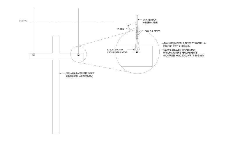
Custom wire rope assemblies are made up of individual wires or strands which have been twisted together to form a strong rope. These ropes can be used as support for hanging objects such as signs, banners, flags, etc. The ropes can also be used to hang items like hammers, tools, etc.
When you think about wire rope cable assembly design options, there are a lot of choices to make. There are different materials to choose from, construction methods, and coating types. Let’s take a look at some of those options.
Galvanized steel and stainless steel are both excellent materials for wire rope applications. Galvanized steel is zinc coated over mild carbon steel and can provide corrosion resistance up to 10 times greater than uncoated mild steel. Stainless steel is similar to galvanized steel except it does not contain zinc. Both materials are very durable and can withstand high loads without failure. They are relatively inexpensive compared to other materials such as aluminum and copper.
Stainless steel is often used for marine applications because of its durability and resistance to saltwater. It is also commonly used for industrial applications where it must endure extreme temperatures and harsh chemicals.
Both materials are strong enough to support heavy loads. However, they are not recommended for use above 600°F due to the risk of fire hazards. If you do need to work with materials that operate above 600°F, stainless steel is generally preferred over galvanized steel.
There are three main types of wire rope: single-strand, multi-strand, and braided. Single-strand wire rope consists of one continuous length of wire. Multi-strand wire rope consists of multiple strands twisted together. Braided wire rope is composed of several strands woven together. All three types of wire rope are manufactured in different sizes and strengths. Sizes range from 2/0 to 5/8 inch in diameter. Strength ratings vary from 10 pounds up to 500 pounds per linear foot.
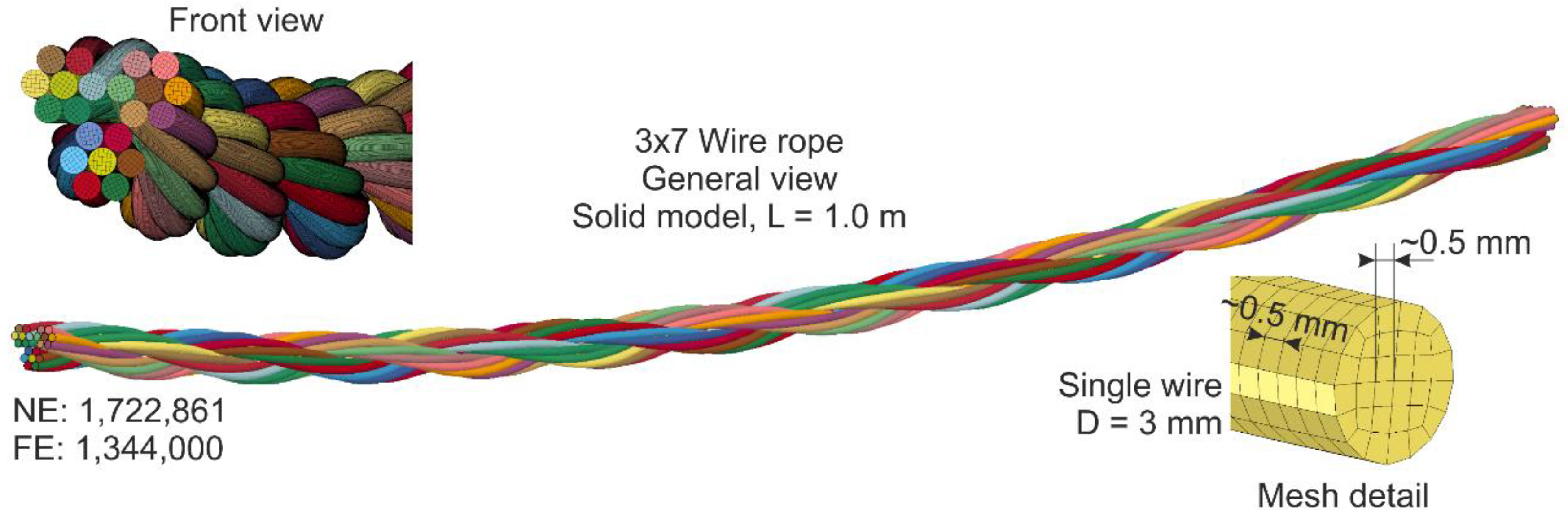
Typically, these cable constructions are made of 7×19, 7×7, or 1×19 wires. The number of wires is determined by the length and diameter of the wire used in the construction.
We offer several options for our end fittings including standard, specialty, and custom. We have many different types of fittings including compression fittings, swage fittings, and threadless fittings.
We have all the latest models of wire rope custom assemblies and standard fittings in our database. Our library contains over 10,0+ different wire rope assemblies with detailed specifications and drawings. You can download these wire rope assembly 2D and 3D CAD models for free.
Cable assemblies are one of the most important parts of a machine. They carry power, signal, data, etc., and must be designed correctly. There are many different types of cables used in manufacturing today, including coaxial cable, shielded wire, twin lead, flat ribbon, stranded conductor, twisted pair, etc. Each type carries a specific function and each needs to be designed differently.
When selecting a cable assembly, there are several things to consider. These include workload, abrading resistance, cycle life, flexibility, environment, cost, and safety. Workload refers to how much force the cable assembly can withstand without breaking. Abrasion resistance is how well the cable resists wear and tear. Cycle life refers to how long the cable assembly can operate without fail. Flexibility is how easily the cable assembly bends. Environment refers to where the cable assembly will be operating. Cost is how much money you want to spend on the cable assembly. Safety is how safe the cable assembly is for workers and customers.
The larger the cable diameter, usually the greater the workload. However, the larger the diameter, the less flexible the cable becomes. This makes the cable hard to bend and difficult to install.
Able hardware – cable assembly manufacturer is here to help you find the perfect cable to meet your needs. We offer thousands of products across hundreds of categories including wire ropes, assemblies, specialty cables, and accessories.
Our comprehensive catalog includes detailed product information, assembly instructions, and technical support. Whether you are looking for a specific type of wire rope, or want to learn how to assemble it yourself, we have what you need.
A wire rope is rated based upon its tensile strength. Tensile strength is measured in pounds per square inch (psi). Wire ropes are typically sold with their tensile strengths expressed in either pounds per linear foot (plf) or psi. To convert plf to psi, multiply the plf value by 0.037. For example, if a wire rope is rated at 50 plf, then its tensile strength would be approximately 5,000 psi.
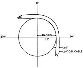
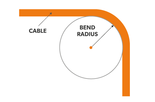
The wire rope’s minimum bending radius is the distance from the centerline of the wire rope to the point where the wire rope begins to kink or buckle. The minimum bending radius depends on the type of wire rope being used.
Stainless steel wire rope assemblies are used as a replacement for conventional galvanized or aluminum wire ropes. The advantages include corrosion resistance, high strength, low weight, and excellent appearance.
The tensile strength of a wire rope is determined by its cross-sectional area and the material it’s made from. The tensile strength of a given wire rope will be constant for all diameters, but the diameter may vary depending on the application.
Stainless steel has excellent corrosion resistance and high mechanical properties. There are two grades of stainless steel: 304 and 316. Both grades have similar chemical compositions, but they differ slightly in their physical characteristics.
Stainless steel is an alloy that contains iron, chromium, nickel, manganese, carbon, and other elements. It is commonly referred to as “304” or “316.”
Cable weights are specified in terms of pounds per linear foot (lbf/ft), which is equal to pounds per lineal yard (lbs/yd). The higher the number, the heavier the cable.
To calculate the weight of a cable, divide the cable’s length by the cable’s nominal diameter. Then multiply this figure by the cable’s weight per pound.
The cost of a custom wire rope cable assembly varies depending on the type of wire rope range, the custom fittings, the diameter, and the length. A typical cost for a custom wire rope cable is $2-$5 per meter.
Custom wire rope cables cost more than traditional steel cables because they are expensive to manufacture. However, You can check the stainless steel cable prices below for reference.
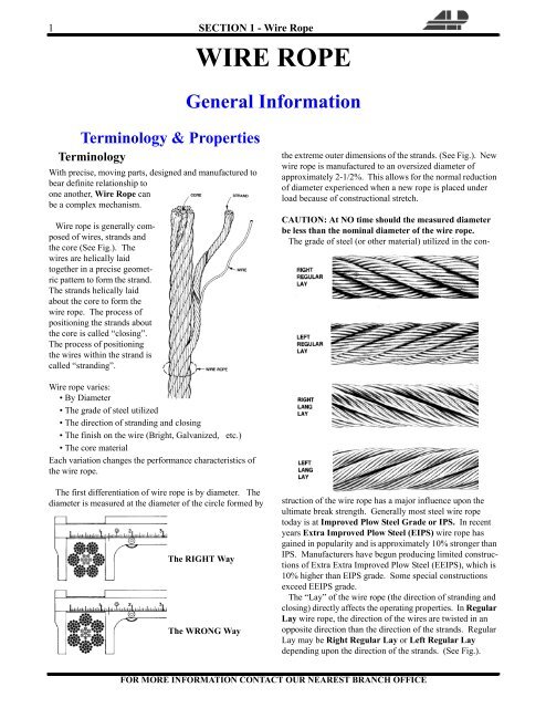
Rope diameter is specified by the user and is generally given in the equipment manufacturer’s instruction manual accompanying the machine on which the rope is to be used.
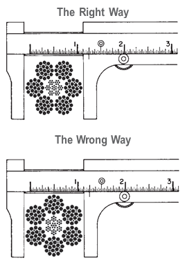
Rope diameters are determined by measuring the circle that just touches the extreme outer limits of the strands— that is, the greatest dimension that can be measured with a pair of parallel-jawed calipers or machinist’s caliper square. A mistake could be made by measuring the smaller dimension.
The right way to unreel.To unreel wire rope from a heavy reel, place a shaft through the center and jack up the reel far enough to clear the floor and revolve easily. One person holds the end of the rope and walks a straight line away from the reel, taking the wire rope off the top of the reel. A second person regulates the speed of the turning reel by holding a wood block against the flange as a brake, taking care to keep slack from developing on the reel, as this can easily cause a kink in the rope. Lightweight reels can be properly unreeled using a vertical shaft; the same care should be taken to keep the rope taut.
The wrong way to unreel.If a reel of wire rope is laid on its flange with its axis vertical to the floor and the rope unreeled by throwing off the turns, spirals will occur and kinks are likely to form in the rope. Wire rope always should be handled in a way that neither twists nor unlays it. If handled in a careless manner, reverse bends and kinks can easily occur.
The right way to uncoil.There is only one correct way to uncoil wire rope. One person must hold the end of the rope while a second person rolls the coil along the floor, backing away. The rope is allowed to uncoil naturally with the lay, without spiraling or twisting. Always uncoil wire rope as shown.
The wrong way to uncoil.If a coil of wire rope is laid flat on the floor and uncoiled by pulling it straight off, spirals will occur and kinking is likely. Torsions are put into the rope by every loop that is pulled off, and the rope becomes twisted and unmanageable. Also, wire rope cannot be uncoiled like hemp rope. Pulling one end through the middle of the coil will only result in kinking.
Great stress has been placed on the care that should be taken to avoid kinks in wire rope. Kinks are places where the rope has been unintentionally bent to a permanent set. This happens where loops are pulled through by tension on the rope until the diameter of the loop is only a few inches. They also are caused by bending a rope around a sheave having too severe a radius. Wires in the strands at the kink are permanently damagedand will not give normal service, even after apparent “re-straightening.”
When wire rope is wound onto a sheave or drum, it should bend in the manner in which it was originally wound. This will avoid causing a reverse bend in the rope. Always wind wire rope from the top of the one reel onto the top of the other.Also acceptable, but less so, is re-reeling from the bottom of one reel to the bottom of another. Re-reeling also may be done with reels having their shafts vertical, but extreme care must be taken to ensure that the rope always remains taut. It should never be allowed to drop below the lower flange of the reel. A reel resting on the floor with its axis horizontal may also be rolled along the floor to unreel the rope.
Wire rope should be attached at the correct location on a flat or smooth-faced drum, so that the rope will spool evenly, with the turns lying snugly against each other in even layers. If wire rope is wound on a smooth-face drum in the wrong direction, the turns in the first layer of rope will tend to spread apart on the drum. This results in the second layer of rope wedging between the open coils, crushing and flattening the rope as successive layers are spooled.
A simple method of determining how a wire rope should be started on a drum. The observer stands behind the drum, with the rope coming towards him. Using the right hand for right-lay wire rope, and the left hand for left lay wire rope, the clenched fist denotes the drum, the extended index finger the oncoming rope.
Clips are usually spaced about six wire rope diameters apart to give adequate holding power. They should be tightened before the rope is placed under tension. After the load is placed on the rope, tighten the clips again to take care of any lessening in rope diameter caused by tension of the load. A wire rope thimble should be used in the eye of the loop to prevent kinking.
U-bolt Clips.There is only one correct method for attaching U-bolt clips to wire rope ends, as shown in TheRightWayimage below. The base of the clip bears on the live end of the rope; the “U” of the bolt bears on the dead end.
Compare this with the incorrect methods. Five of the six clips shown are incorrectly attached—only the center clip in the top view is correct. When the “U” of the clip bears on the live end of the rope, there is a possibility of the rope being cut or kinked, with subsequent failure.
Proper seizing and cutting operations are not difficult to perform, and they ensure that the wire rope will meet the user’s performance expectations. Proper seizings must be applied on both sides of the place where the cut is to be made. In a wire rope, carelessly or inadequately seized ends may become distorted and flattened, and the strands may loosen. Subsequently, when the rope is operated, there may be an uneven distribution of loads to the strands; a condition that will significantly shorten the life of the rope.
Either of the following seizing methods is acceptable. Method No. 1 is usually used on wire ropes over one inch in diameter. Method No. 2 applies to ropes one inch and under.
Method No. 1: Place one end of the seizing wire in the valley between two strands. Then turn its long end at right angles to the rope and closely and tightly wind the wire back over itself and the rope until the proper length of seizing has been applied. Twist the two ends of the wire together, and by alternately pulling and twisting, draw the seizing tight.
The Seizing Wire. The seizing wire should be soft or annealed wire or strand. Seizing wire diameter and the length of the seize will depend on the diameter of the wire rope. The length of the seizing should never be less than the diameter of the rope being seized.
Proper end seizing while cutting and installing, particularly on rotation-resistant ropes, is critical. Failure to adhere to simple precautionary measures may cause core slippage and loose strands, resulting in serious rope damage. Refer to the table below ("Suggested Seizing Wire Diameters") for established guidelines. If core protrusion occurs beyond the outer strands, or core retraction within the outer strands, cut the rope flush to allow for proper seizing of both the core and outer strands.
The majority of wire rope problems occurring during operation actually begin during installation, when the rope is at its greatest risk of being damaged. Proper installation procedures are vital in the protection and performance of wire rope products.
Until the rope is installed it should be stored on a rack, pallet or reel stand in a dry, well-ventilated storage shed or building. Tightly sealed and unheated structures should be avoided as condensation between rope strands may occur and cause corrosion problems. If site conditions demand outside storage, cover the rope with waterproof material and place the reel or coil on a support platform to keep it from coming directly in contact with the ground.
While lubrication is applied during the manufacturing process, the wire rope must still be protected by additional lubrication once it is installed. Lubricants will dry out over a period of time and corrosion from the elements will occur unless measures are taken to prevent this from happening. When the machine becomes idle for a period of time, apply a protective coating of lubricant to the wire rope. Moisture (dew, rain, and snow) trapped between strands and wires will create corrosion if the rope is unprotected. Also apply lubricant to each layer of wire rope on a drum because moisture trapped between layers will increase the likelihood of corrosion.
Always use the nominal diameter as specified by the equipment manufacturer. Using a smaller diameter rope will cause increased stresses on the rope and the probability of a critical failure is increased if the rated breaking strength does not match that of the specified diameter. Using a larger diameter rope leads to shorter service life as the rope is pinched in the sheave and drum grooves which were originally designed for a smaller diameter rope. Just as using a different diameter rope can create performance problems, so can the use of an excessively undersized or oversized rope.
Measure the wire rope using a parallel-jawed caliper as discussed in Measuring Rope Diameter at the top of this page. If the rope is the wrong size or outside the recommended tolerance, return the rope to the wire rope supplier. It is never recommended nor permitted by federal standards to operate cranes with the incorrect rope diameter. Doing so will affect the safety factor or reduce service life and damage the sheaves and drum. Note that in a grooved drum application, the pitch of the groove may be designed for the rope’s nominal diameter and not the actual diameter as permitted by federal standards.
Wire rope can be permanently damaged by improper unreeling or uncoiling practices. The majority of wire rope performance problems start here.Improper unreeling practices lead to premature rope replacement, hoisting problems and rope failure.
Place the payout reel as far away from the boom tip as is practical, moving away from the crane chassis. Never place the payout reel closer to the crane chassis than the boom point sheave. Doing so may introduce a reverse bend into the rope and cause spooling problems. Follow the guidelines highlighted under Unreeling and Uncoiling and Drum Winding. Take care to determine whether the wire rope will wind over or under the drum before proceeding. If the wire rope supplier secured the end of the rope to the reel by driving a nail through the strands, ask that in the future a U-bolt or other nondestructive tie-down method be used; nails used in this manner damage the rope.
Take extra precaution when installing lang lay, rotation-resistant, flattened strand or compacted ropes. Loss of twist must be avoided to prevent the strands from becoming loosened, causing looped wire problems.
The end of the rope must be securely and evenly attached to the drum anchorage point by the method recommended by the equipment manufacturer. Depending on the crane’s regulatory requirements, at least two to three wraps must remain on the drum as dead wraps when the rope is unwound during normal operations. Locate the dead end rope anchorage point on the drum in relation to the direction of the lay of the rope. Do not use an anchorage point that does not correspond with the rope lay. Mismatching rope lay and anchorage point will cause the wraps to spread apart from each other and allow the rope to cross over on the drum. Very gappy winding will occur resulting in crushing damage in multilayer applications.
Back tension must be continually applied to the payout reel and the crewman installing the rope must proceed at a slow and steady pace whether the drum is smooth or grooved.Regardless of the benefits of a grooved drum, tension must be applied to ensure proper spooling. An improperly installed rope on a grooved drum will wear just as quickly as an improperly installed rope on a smooth drum. If a wire rope is poorly wound and as a result jumps the grooves, it will be crushed and cut under operating load conditions where it crosses the grooves.
Every wrap on the first or foundation layer must be installed very tightly and be without gaps. Careless winding results in poor spooling and will eventually lead to short service life. The following layers of rope must lay in the grooves formed between adjacent turns of the preceding layer of rope. If any type of overwind or cross-winding occurs at this stage of installation and is not corrected immediately, poor spooling and crushing damage will occur.
On a multilayer spooling drum be sure that the last layer remains at least two rope diameters below the drum flange top. Do not use a longer length than is required because the excess wire rope will cause unnecessary crushing and may jump the flange. Loose wraps that occur at any time must be corrected immediately to prevent catastrophic rope failure.
The use of a mallet is acceptable to ensure tight wraps, however a steel-faced mallet should be covered with plastic or rubber to prevent damage to the rope wires and strands.
Rotation-resistant ropes of all constructions require extra care in handling to prevent rope damage during installation. The lay length of a rotation-resistant rope must not be disturbed during the various stages of installation. By introducing twist or torque into the rope, core slippage may occur—the outer strands become shorter in length, the core slips and protrudes from the rope. In this condition the outer strands become over- loaded because the core is no longer taking its designed share of the load. Conversely, when torque is removed from a rotation-resistant rope core slippage can also occur. The outer strands become longer and the inner layers or core become overloaded, reducing service life and causing rope failure.
The plain end of a wire rope must be properly secured. If the entire cross section of the rope is not firmly secured, core slippage may occur, causing the core to pull inside the rope’s end and allowing it to protrude elsewhere, either through the outer strands (popped core) or out the other end of the line. The outer layer of the outside strands may also become overloaded as there is no complete core-to-strand support.
Secure the ends of the rope with either seizing or welding methods as recommended under Seizing Wire Rope. It is imperative that the ends be held together tightly and uniformly throughout the entire installation procedure, including attaching the end through the wedge socket and the drum dead end wedge
When installing a new line, connect the old line to the new line by using a swivel-equipped cable snake or Chinese finger securely attached to the rope ends. The connection between the ropes during change-out must be very strong and prevent torque from the old rope being transferred into the new rope.Welding ropes together or using a cable snake without the benefit of a swivel increases the likelihood of introducing torque into the new rope. A swivel-equipped cable snake is not as easy as welding the ropes, but this procedure can be mastered with a little patience and practice.
A competent person must begin a visual inspection prior to each shift the equipment is used, which must be completed before or during that shift. The inspection must consist of observation of wire ropes (running and standing) that are likely to be in use during the shift for apparent deficiencies, including those listed in paragraph (a)(2) of this section. Untwisting (opening) of wire rope or booming down is not required as part of this inspection.
Significant distortion of the wire rope structure such as kinking, crushing, unstranding, birdcaging, signs of core failure or steel core protrusion between the outer strands.
In running wire ropes: Six randomly distributed broken wires in one rope lay or three broken wires in one strand in one rope lay, where a rope lay is the length along the rope in which one strand makes a complete revolution around the rope.
In rotation resistant ropes: Two randomly distributed broken wires in six rope diameters or four randomly distributed broken wires in 30 rope diameters.
In pendants or standing wire ropes: More than two broken wires in one rope lay located in rope beyond end connections and/or more than one broken wire in a rope lay located at an end connection.
If a deficiency in Category I (see paragraph (a)(2)(i) of this section) is identified, an immediate determination must be made by the competent person as to whether the deficiency constitutes a safety hazard. If the deficiency is determined to constitute a safety hazard, operations involving use of the wire rope in question must be prohibited until:
If the deficiency is localized, the problem is corrected by severing the wire rope in two; the undamaged portion may continue to be used. Joining lengths of wire rope by splicing is prohibited. If a rope is shortened under this paragraph, the employer must ensure that the drum will still have two wraps of wire when the load and/or boom is in its lowest position.
If a deficiency in Category II (see paragraph (a)(2)(ii) of this section) is identified, operations involving use of the wire rope in question must be prohibited until:
The employer complies with the wire rope manufacturer"s established criterion for removal from service or a different criterion that the wire rope manufacturer has approved in writing for that specific wire rope (see § 1926.1417),
If the deficiency is localized, the problem is corrected by severing the wire rope in two; the undamaged portion may continue to be used. Joining lengths of wire rope by splicing is prohibited. If a rope is shortened under this paragraph, the employer must ensure that the drum will still have two wraps of wire when the load and/or boom is in its lowest position.
If the deficiency (other than power line contact) is localized, the problem is corrected by severing the wire rope in two; the undamaged portion may continue to be used. Joining lengths of wire rope by splicing is prohibited. Repair of wire rope that contacted an energized power line is also prohibited. If a rope is shortened under this paragraph, the employer must ensure that the drum will still have two wraps of wire when the load and/or boom is in its lowest position.
Where a wire rope is required to be removed from service under this section, either the equipment (as a whole) or the hoist with that wire rope must be tagged-out, in accordance with § 1926.1417(f)(1), until the wire rope is repaired or replaced.
The inspection must include any deficiencies that the qualified person who conducts the annual inspection determines under paragraph (c)(3)(ii) of this section must be monitored.
Wire ropes on equipment must not be used until an inspection under this paragraph demonstrates that no corrective action under paragraph (a)(4) of this section is required.
At least every 12 months, wire ropes in use on equipment must be inspected by a qualified person in accordance with paragraph (a) of this section (shift inspection).
The inspection must be complete and thorough, covering the surface of the entire length of the wire ropes, with particular attention given to all of the following:
Exception: In the event an inspection under paragraph (c)(2) of this section is not feasible due to existing set-up and configuration of the equipment (such as where an assist crane is needed) or due to site conditions (such as a dense urban setting), such inspections must be conducted as soon as it becomes feasible, but no longer than an additional 6 months for running ropes and, for standing ropes, at the time of disassembly.
If a deficiency is identified, an immediate determination must be made by the qualified person as to whether the deficiency constitutes a safety hazard.
If the deficiency is localized, the problem is corrected by severing the wire rope in two; the undamaged portion may continue to be used. Joining lengths of wire rope by splicing is prohibited. If a rope is shortened under this paragraph, the employer must ensure that the drum will still have two wraps of wire when the load and/or boom is in its lowest position.
If the qualified person determines that, though not presently a safety hazard, the deficiency needs to be monitored, the employer must ensure that the deficiency is checked in the monthly inspections.
All documents produced under this section must be available, during the applicable document retention period, to all persons who conduct inspections under this section.
Wire rope is often used in slings because of its strength, durability, abrasion resistance and ability to conform to the shape of the loads on which it is used. In addition, wire rope slings are able to lift hot materials.
Wire rope used in slings can be made of ropes with either Independent Wire Rope Core (IWRC) or a fiber-core. It should be noted that a sling manufactured with a fiber-core is usually more flexible but is less resistant to environmental damage. Conversely, a core that is made of a wire rope strand tends to have greater strength and is more resistant to heat damage.
Wire rope may be manufactured using different rope lays. The lay of a wire rope describes the direction the wires and strands are twisted during the construction of the rope. Most wire rope is right lay, regular lay. This type of rope has the widest range of applications. Wire rope slings may be made of other wire rope lays at the recommendation of the sling manufacturer or a qualified person.
Wire rope slings are made from various grades of wire rope, but the most common grades in use are Extra Improved Plow Steel (EIPS) and Extra Extra Improved Plow Steel (EEIPS). These wire ropes are manufactured and tested in accordance with ASTM guidelines. If other grades of wire rope are used, use them in accordance with the manufacturer"s recommendations and guidance.
When selecting a wire rope sling to give the best service, consider four characteristics: strength, ability to bend without distortion, ability to withstand abrasive wear, and ability to withstand abuse.
Rated loads (capacities) for single-leg vertical, choker, basket hitches, and two-, three-, and four-leg bridle slings for specific grades of wire rope slings are as shown in Tables 7 through 15.
Rated loads for a sling in a choker hitch are the values shown in Table 7, 9, 11, 13, 14, or 15, provided that the angle of the choke is 120 degrees or more (Fig. 2). Use the values in Fig. 2 or those from the sling manufacturer or a qualified person for angles of choke less than 120 degrees.
Ensure that slings made of rope with 6×19 and 6x37 classifications and cable slings have a minimum clear length of rope 10 times the component rope diameter between splices, sleeves, or end fittings unless approved by a qualified person,
Ensure that braided slings have a minimum clear length of rope 40 times the component rope diameter between the loops or end fittings unless approved by a qualified person,
Ensure that grommets and endless slings have a minimum circumferential length of 96 times the body diameter of the grommet or endless sling unless approved by a qualified person, and
Perform welding of handles or other accessories to end attachments, except covers to thimbles, before assembly of the sling. Ensure that welded end attachments are proof tested by the manufacturer or a qualified person. Retain the certificates of proof test and make them available for examination.
Do not use wire rope clips to fabricate wire rope slings, except where the application precludes the use of prefabricated slings and where the sling is designed for the specific application by a qualified person,
Although OSHA"s sling standard does not require you to make and maintain records of inspections, the ASME standard contains provisions on inspection records.[3]
Use damaged slings only after they are repaired, reconditioned, and proof tested by the sling manufacturer or a qualified person using the following criteria:
Ensure that wire rope slings have suitable characteristics for the type of load, hitch, and environment in which they will be used and that they are not used with loads in excess of the rated load capacities described in the appropriate tables. When D/d ratios (Fig. 4) are smaller than those listed in the tables, consult the sling manufacturer. Follow other safe operating practices, including:
Ensure that multiple-leg slings are selected according to Tables 7 through 15 when used at the specific angles given in the tables. Ensure that operations at other angles are limited to the rated load of the next lower angle given in the tables or calculated by a qualified person,
When D/d ratios (see Fig. 6) smaller than those cited in the tables are necessary, ensure that the rated load of the sling is decreased. Consult the sling manufacturer for specific data or refer to the WRTB (Wire Rope Technical Board) Wire Rope Sling Users Manual, and
Ensure that all portions of the human body are kept away from the areas between the sling and the load and between the sling and the crane or hoist hook,
When using a basket hitch, ensure that the legs of the sling contain or support the load from the sides, above the center of gravity, so that the load remains under control,
Ensure that the load applied to the hook is centered in the base (bowl) of the hook to prevent point loading on the hook, unless the hook is designed for point loading,
Before initial use, ensure that all new swaged-socket, poured-socket, turnback-eye, mechanical joint grommets, and endless wire rope slings are proof tested by the sling manufacturer or a qualified person.
Permanently remove from service fiber-core wire rope slings of any grade if they are exposed to temperatures in excess of 180 degrees F (82 degrees C).
Follow the recommendations of the sling manufacturer when you use metallic-core wire rope slings of any grade at temperatures above 400 degrees F (204 degrees C) or below minus 40 degrees F (minus 40 degrees C).
Abstract: the elevator wire rope mainly refers to the traction steel rope. The traction rope bears all the weight of the elevator, and in the operation of the elevator, it bends in one direction or alternately around the traction wheel, guide wheel or anti rope wheel. The steel rope also bears high specific pressure in the rope groove, so the steel rope must have high strength, flexibility and wear resistance. This paper analyzes the main factors affecting the fatigue life from the installation, use, maintenance and production process of the steel rope.
The steel rope is a load-bearing element in the elevator, which almost bears all the weight of the elevator. The quality of the steel rope will directly affect the safety of the elevator operation. In the operation of the elevator, the wire rope is bent unidirectionally or alternately around the traction wheel, guide wheel and anti rope wheel. The steel wire rope bears high specific pressure in the rope groove, so the steel wire rope for elevator is required to have high strength, flexibility and wear resistance.
The steel rope is generally circular strand structure, which is mainly composed of steel wire strand and rope core. Steel wire is the basic component of wire rope, which requires high strength and toughness. The strand of wire rope is made of steel wire, usually 8 to 9 strands. The core is usually made of sisal fiber or synthetic fiber of alkene.
The factors affecting the service life of steel rope for elevator mainly include the following aspects: safety factor of traction steel wire rope, tensile load of steel rope, bending radius of steel rope in use, material and groove type of traction wheel, material and twisting quality of steel wire rope itself, lubrication of steel wire rope, use and maintenance of wire rope, etc.
The safety factor of elevator partly depends on the safety factor of traction wire rope. There are static and dynamic loads in the operation of elevator wire rope, but the main factor affecting the service life of steel wire rope is static load. In practical application, in order to simplify calculation, only static load is considered for practical calculation. The diameter of steel wire rope for elevator is very important. In order to improve the strength of steel wire rope and prolong its service life, the diameter of steel wire rope must be the most appropriate size. For the calculation of safety factor, the corresponding safety factor is calculated according to the national approved standard by selecting the diameter of steel wire rope, so as to ensure the safety performance of steel wire rope for elevator The service life of the rope.
The tensile load is the load that the elevator wire rope bears in the operation of the elevator and the variation in its movement. In a well maintained and debugged elevator, the load of each steel rope in the operation process should be basically the same. If the tension of each rope is uneven in operation due to improper maintenance of the wire rope, the compressive stress between one or several wire ropes and the wheel groove will be greatly increased, which will accelerate the wear of the wire rope and directly affect the service life of the wire rope. Therefore, it is clearly stipulated in the elevator supervision and inspection rules that the deviation between the traction wire rope tension and the average value is not more than 5%.
The curvature radius of steel rope is determined according to the pitch diameter and relative position of traction wheel, anti rope pulley and guide wheel in the use of steel wire rope. Different positions and different pitch diameter determine the bending times and bending stress of steel wire rope in use. The bending stress is inversely proportional to the pitch diameter of each wheel. Article 9.2.1 of gb7588-1995 < Safety Code for elevator manufacture and installation > > stipulates that the ratio of pitch diameter of traction wheel, pulley or drum to the nominal diameter of suspension rope shall not be less than 40 regardless of the number of strands of steel wire rope. During the bending process of steel wire rope, the relative displacement of steel wire in the strand occurs, and there is wear inside. The greater the bending stress, the greater the contact stress between strands With the accumulation of time, the steel wire will break because of stress concentration. Therefore, under the condition that the traction capacity is satisfied, the radius of curvature should be increased as much as possible, the number of rope wheels should be reduced, the reverse bending or twisting of wire rope should be avoided, and the bending stress of steel rope should be reduced in the process of using, so as to reduce the adverse factors on the service life of wire rope.
4.1 the groove type and material of traction wheel are closely related to the service life of steel rope. Generally speaking, the wear of steel rope should be very slow due to its higher hardness than rope operation. However, due to the matching of the rope tension and groove type, the elevator wire rope slips, eccentric wear and roll in the groove, which causes wear with the rope groove. Generally, there are semicircular groove, semicircular groove with notch and V-groove. The contact area between the semicircular groove and the rope is relatively large, the specific pressure distribution of the wire rope in the groove is more uniform, and the wear of the rope is relatively small. In order to limit the deterioration of traction conditions due to wear, the lower part of traction wheel is often cut when the rope groove is not subject to additional hardening treatment. The specific pressure distribution of steel rope in the semicircular groove with notch is relatively concentrated, and the specific pressure increases when the notch angle increases. However, due to the small contact area between V-groove and steel wire rope, the specific pressure distribution of steel rope in the rope groove is relatively concentrated, the V-shaped angle is reduced, the specific pressure is increased, and the damage to the steel wire rope is greater in use, which affects the service life of the wire rope.
4.2 generally, the hardness and elastic modulus of the groove should be considered for the material of traction wheel. If the material with soft material is used, the external stress will be reduced, but the wear of the steel wire rope will turn to the inside of the wire rope, and the fracture of the steel wire inside the wire rope will increase. Therefore, it is suggested to use polyurethane rope groove liner on the traction wheel. The liner is embedded into the corresponding groove, and transverse grooves are processed on the liner. The friction coefficient of the appropriate grooved wheel to the non lubricated steel wire rope is almost unchanged, and the polyurethane wear resistance is also very good, which improves the service life of the liner and greatly increases the service life of the elevator wire rope.
Fatigue is one of the main reasons for more broken wires in the process of using elevator wire rope. The broken wire of elevator wire rope moving around traction wheel is the result of bending fatigue and wear fatigue. The research and understanding of the production process and fatigue essence is helpful to take measures in the production process, improve the fatigue resistance of elevator wire rope and prolong the service life of elevator wire rope It can reduce the operation cost and improve the safety and reliability of elevator operation.
The best metallographic structure is suitable for drawing steel wire. In the production process, due to the surface damage of steel wire, or serious scratches, scars, rust pits, and non-metallic inclusions formed in the steel smelting process, it is easy to form fatigue sources. The content and particle size of non-metallic inclusions in steel have a significant impact on the fatigue performance of steel rope, because the reticular ferrite in the metallographic structure after sorbite can promote the rapid propagation of fatigue crack, so the network ferrite is not allowed in lead quenched steel wire. The austenitizing temperature of steel wire and the isothermal transformation temperature of lead quenching determine the generation of network ferrite Qualitative influence, the automatic control furnace temperature and lead temperature technology of lead quenching production line is conducive to the uniformity of sorbite structure, and the lead liquid circulation is conducive to the uniform sorbite structure of steel wire at different positions in the lead pot, which can ensure that the strength of steel wire after lead quenching is relatively uniform, so as to ensure the minimum fluctuation range of mechanical properties of steel wire after drawing. The optimum combination of strength and toughness is beneficial to improve the fatigue resistance of wire rope. Generally, straight wire drawing machine and water box drawing machine belong to non torsion drawing, which is beneficial to obtain high strength and high toughness steel wire. The lubrication and cooling capacity of water tank is better than that of dry wire drawing machine. Larger diameter drum and tower wheel can reduce the bending deformation of steel wire winding. Multi pass low compression ratio drawing can obtain high toughness.
The structure of wire rope has an important influence on the fatigue resistance of steel rope. Generally, surface contact steel rope is caused by line contact wire rope, and wire contact wire rope is caused by


 8613371530291