
what is the minimum bending radius of wire rope brands

This website is using a security service to protect itself from online attacks. The action you just performed triggered the security solution. There are several actions that could trigger this block including submitting a certain word or phrase, a SQL command or malformed data.
To obtain reasonable service life from your aircraft cable or wire rope, you must choose the optimal diameter of rope and sheave for your application. In general, the larger the size of the drum or pulley with respect to the wire diameter, the longer the service life. The opposite is also true: in general, the smaller the size of the drum or pulley with respect to your wire rope, the shorter the service life. Keep these relationships between cable, rope, and pulleys in mind when specifying the competence you use in your application.
The tables below provide the minimum recommended pulley diameter as well as the approximate bend radius of the rope. You"ll notice that the calculation is approximately half of the minimum recommended pulley tread diameter. Whether running fully over the sheave or drum, or some fraction thereof, check your design against the recommendations to better understand the service life you can expect in relation to the other factors involved.
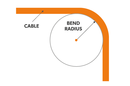
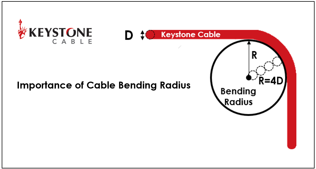
Bend radius is the minimum radius a pipe, cable, wire, sheet, cable, tube or hose can bend without damaging it (including kinking). The smaller the radius, the greater is the flexibility of the material. The minimum bend radius is the radius below which an object should not be bent.
Factors which influence the minimum bending radius include the cable size, the cable construction, the conductor type and the sheathing and insulation types used. The bending radius is normally expressed as a factor of the overall dimension of the cable for example, 6D or 6x the outer diameter of the cable.
According to Table 1, the minimum bend radius is found to be six times the cable’s overall diameter. The overall diameter of the cable is given as 2.08 inches in the product catalog. Multiplying 2.08 inches by six, we get 12.48 inches.
The minimum bend radius will vary depending on the specific fiber cable. However, in general, the minimum bend radius should not be less than ten times the outer diameter (OD) of the fiber cable. Thus a 3 mm cable should not have any bends less than 30mm in radius.
We recommend a minimum bend radius of 1t for all sheet metal parts. Thus the smallest radius of any bend in a sheet should be at least equal to the thickness of the sheet. For example, if the thickness of the sheet is 1 mm, the minimum bend radius should be 1 mm.
However, in general, the minimum bend radius should not be less than ten times the outer diameter (OD) of the fiber cable. Thus a 3 mm cable should not have any bends less than 30mm in radius. Telcordia recommends a minimum 38 mm bend radius for 3 mm patch cords.
thick, grade 350 and 400 may have a minimum bend radius of 2.5 times the material thickness when transverse bending, while longitudinal bending may require a minimum bend radius that’s 3.75 times the material thickness. And between 0.8 and 2 in.
Flange length must be at least 4 times the material thickness. It is recommended to use the same radii across all bends, and flange length must be at least 4 times the material thickness.
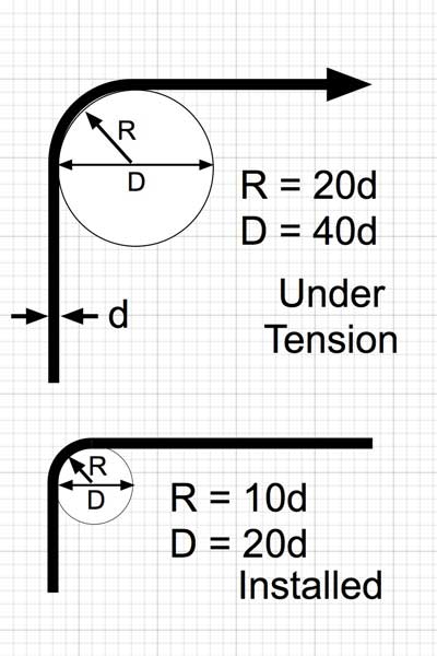
The minimum bend radius A typical value for a cable under no load conditions, or “unloaded,” is 10 times the cable’s outside diameter. When a cable is under tensile load or “loaded,” the minimum bend radius is usually 15 times the cable’s outside diameter. Learn more: Fibre cable and pulling eyes.
The normal recommendation for fiber optic cable bend radius is the minimum bend radius under tension during pulling is 20 times the diameter of the cable. When not under tension (after installation), the minimum recommended long term bend radius is 10 times the cable diameter.
Bend radius is the minimum radius a pipe, cable, wire, sheet, cable, tube or hose can bend without damaging it (including kinking). The smaller the radius, the greater is the flexibility of the material. The minimum bend radius is the radius below which an object should not be bent.
Recommended Bend Radius Rope Diameter Minimum Recommended Pulley Tread Diamete Approximate Bend Radius .009″ 3/8″ 3/16″ .014″ 5/8″ 5/16″ .018″ 13/16″ 13/32″ .024″ 1″ 1/2″
Answer: SHD-GC is a shielded mining cable. According to Table 1, the minimum bend radius is found to be six times the cable’s overall diameter. The overall diameter of the cable is given as 2.08 inches in the product catalog. Multiplying 2.08 inches by six, we get 12.48 inches.
For cable connectors such as ferrules or clamps, holding the cable in place may also flex the cable beyond its recommended bend radius. In addition, pulling the cable at an improper angle in relation to the connector may cause damage. Questions?
The bend radius is the radius at which a cable can be bent without damaging it (including kinking). The smaller the radius, the greater the required flexibility of the material. A frequently asked question in this context is: how much can we bend a cable without damaging it or impairing its function? The answer depends mainly on the particular cable being considered. There are several industry standards, such as IEEE 1185, ICEA S-75-381, ICEA S-66-524 or ICEA S-68-516, which provide minimal bend radii for many different cable types.
The minimum bend radius is the radius below which an object cannot be bent. In many installations, cable carriers are used, so the question arises: how do we select the bend radius of a cable or a cable carrier?
When deciding on a cable management system, there are several ways to extend the service life of the cable. One of the most important factors is the selection of the right bend radius for the cable carrier. It is important that the radius (except, perhaps, in space constrained applications) is greater than the recommended minimum bend radius of the cables. One of the key factors in long service life and operational reliability is choosing the right radius for the cable carrier. All cable carriers have several bend radii to choose from and each manufacturer proposes a minimum bend radius . The radius chosen for the cable carrier depends on the cable with the largest diameter.General rules and recommendations for selecting the radius
Do not exceed the manufacturer"s recommended minimum radius - but the maximum radius is optimal. Basically, cables with flexible specifications that move must be supported so that the connection points are not mechanically stressed and a sharp bend is avoided. If this is achieved by a loop, the cable must be provided with a bend radius of at least 10 times the diameter of the cable. The larger the radius, the less stress is exerted on the cables, which ensures a longer service life. It should be noted that the minimum bend radius is partially based on a temperature range for the bending. Particular care should be taken when the ambient temperature reaches or exceeds this temperature for the cable.
This is especially true for cryogenic applications where thermoplastic cables tend to stiffen when exposed to cold. Rigid cables can increase the radius of the cable carrier and lead to mechanical errors. It is recommended to use a cable with a PUR or TPE jacket at low temperature and/or to consult the manufacturer for recommendations on bend radii. For space constrained applications, the cable carrier radius must be less than the recommended minimum bend radius for the filling pack. This is not ideal, but if it cannot be avoided, cables designed specifically for low bend radius installations should be used. The igus chainflex range includes load-bearing control cables, servo and motor cables or robot cables as well as encoder cables, bus cables and data cables, which can be safely used in demanding environments and are characterised by their very long service life.
A long time ago when I was first running Ethernet cabling, I was told by an older installer that the best way to determine how much you could bend a cable was with a DVD/CD. He said the cable should not curve tighter than the outer edge of the disk. I thought this was a great rule of thumb! This was wise advice then, but a bit outdated today. Further, this was in the context of RG6 coaxial cable, a different animal than what we are talking about here.
Why should you be concerned with how much to bend an Ethernet cable (or any cable for that matter)? Think of your cable as a garden hose. Water should flow through it freely. Now, put a nice hard kink in that hose and the water stops. When discussing Ethernet cable, this is not a bad way of thinking about it. A kink, or too tight of a bend, can and does interfere with the signaling characteristics of the cable. The hose analogy is an extreme example as the water stops altogether. In the case of Ethernet cable the speeds at which devices connect may be reduced, or there may be consistent packet errors. Or even worse…intermittent and hard to track down packet errors.
Arethere rules for how much you can bend Ethernet cable? Yes. According to ANSI/TIA-568-0.E, a manufacturer’s guidance around maximum bend radius trumps any generic guidelines. In absence of manufacturer stated rules, the generic guidance isfour times (4X)the cable jacket diameter for U/UTP Ethernet cable oreight times (8X)for F/UTP (and SF/FTP)solidcopper structure cable.
These rules change forstrandedcopper Ethernet patch cabling, however. Patch cables are held to the 4X rule, whether shielded or not. If you are confused about the difference between stranded and solid copper conductor cabling, see .
For trueCABLE U/UTP solid copper unshielded cable, we follow the ANSI/TIA guidelines. The inside radius of bends should be no tighter than 4X theouter diameter (OD) of the cable.For trueCABLE F/UTP solid copper shielded cable the inside radius of the cable should not be tighter than 7X the OD of the cable. See the table below for actual measurements, giving a far more useful dimension, the bend diameter.
If you are dealing with cable that is not trueCABLE brand, and that manufacturer provided no guidance around bend radius limitations,there is a nice little formula and it does not matter whether it is calculated in millimeters or inches. If the Ethernet cable has a specified OD published by the manufacturer, this formula is easy to apply.
When putting this into practice, visualizing a bend radius is tough. Rather than rely upon bend radius to be your guide, rely on bend diameter. Bend diameter is simply calculated as:
The result is far easier to visualize. Diameter is the width of the inside of a circle. For an example of how this looks in practice, here are some pictures that may help.
I am sure many out there will provide stories about how much tighter they can bend a cable and get away with it. Sometimes, a sharper turn is simply unavoidable. My only advice is to obey the rules of thumb, but use common sense and don’t bend a cable at a right angle! Performance testing is the best way to confirm your cabling works as expected.
trueCABLE presents the information on our website, including the “Cable Academy” blog and live chat support, as a service to our customers and other visitors to our website subject to our website

In this article, we outline important technical topics related to wire rope. This information has been sourced from and approved by Bridon American. Use the outline to skip to specific sections:
Any assembly of steel wires spun into a helical formation, either as a strand or wire rope (when subjected to a tensile load) can extend in three separate phases, depending on the magnitude of the applied load.
At the commencement of loading a new rope, extension is created by the bedding down of the assembled wires with a corresponding reduction in overall diameter. This reduction in diameter is accommodated by a lengthening of the helical lay. When sufficiently large bearing areas have been generated on adjacent wires to withstand the circumferential compressive loads, this mechanically created extension ceases and the extension in Phase 2 commences. The Initial Extension of any rope cannot be accurately determined by calculation and has no elastic properties.
The practical value of this characteristic depends upon many factors, the most important being the type and construction of rope, the range of loads and the number and frequency of the cycles of operation. It is not possible to quote exact values for the various constructions of rope in use, but the following approximate values may be employed to give reasonably accurate results.
Following Phase 1, the rope extends in a manner which complies approximately with Hookes Law (stress is proportional to strain) until the limit of proportionality or elastic limit is reached.
It is important to note that wire ropes do not possess a well defined Young’s Modulus of Elasticity, but an ‘apparent’ Modulus of Elasticity can be determined between two fixed loads.
By using the values given, it is possible to make a reasonable estimate of elastic extension, but if greater accuracy is required, it is advisable to carry out a modulus test on an actual sample of the rope. As rope users will find it difficult to calculate the actual metallic steel area, the values can be found in the Wire Rope Users Manual or obtained from Bridon Engineering.
The permanent, non-elastic extension of the steel caused by tensile loads exceeding the yield point of the material. If the load exceeds the Limit of Proportionality, the rate of extension will accelerate as the load is increased until a loading is reached at which continuous extension will commence, causing the wire rope to fracture without any further increase of load.
The coefficient of linear expansion (∝) of steel wire rope is (6.94 x 10⁻⁶ per °F) and therefore the change in length of 1 foot of rope produced by a temperature change of t (°F) would be:
Example: What will be the total elongation of a 200 ft. length of 1-1/8″ diameter Blue Strand 6 x 41 IWRC wire rope at a tension of 20,000 Ibs. and with an increase in temperature of 20°F?
In addition to bending stresses experienced by wire ropes operating over sheaves or pulleys, ropes are also subjected to radial pressure as they make contact with the sheave. This pressure sets up shearing stresses in the wires, distorts the rope’s structure and affects the rate of wear of the sheave grooves. When a rope passes over a sheave, the load on the sheave bearing results from the tension in the rope and the angle of rope contact. It is independent of the diameter of the sheave.
Assuming that the rope is supported in a well fitting groove, then the pressure between the rope and the groove is dependent upon the rope tension and diameter, but is independent of the arc of contact.
It must be realized that this method of estimation of pressure assumes that the area of contact of the rope in the groove is on the full rope diameter, whereas in fact only the crowns of the outer wires are actually in contact with the groove. It is estimated that the local pressures at these contact points may be as high as five times those calculated. If the pressure is high, the compressive strength of the material in the groove may be insufficient to prevent excessive wear and indentation, and this in turn will damage the outer wires of the rope and effect its working life.
As with bending stresses, stresses due to radial pressure increase as the diameter of the sheave decreases. Although high bending stresses generally call for the use of flexible rope constructions having relatively small diameter outer wires, these have less ability to withstand heavy pressures than do the larger wires in the less flexible constructions. If the calculated pressures are too high for the particular material chosen for the sheaves or drums or indentations are being experienced, consideration should be given to an increase in sheave or drum diameter. Such a modification would not only reduce the groove pressure, but would also improve the fatigue life of the rope.
The pressure of the rope against the sheave also causes distortion and flattening of the rope structure. This can be controlled by using sheaves with the correct groove profile, which, for general purposes, suggests a recommended groove diameter of nominal rope diameter +6%. The profile at the bottom of the groove should be circular over an angle of approximately 120° and the angle of flare between the sides of the sheave should be approximately 52°.
Bend fatigue testing of ropes usually consists of cycling a length of rope over a sheave while the rope is under a constant tension. As part of their ongoing development program, Bridon has tested literally thousands of ropes in this manner over the years on their own in-house design bend testing equipment.
Through this work, Bridon has been able to compare the effects of rope construction, tensile strength, lay direction, sheave size, groove profile and tensile loading on bend fatigue performance under ideal operating conditions. At the same time it has been possible to compare rope life to discard criteria (e.g. as laid down in ISO 4309) with that to complete failure of the rope, i.e. to the point where the rope has been unable to sustain the load any longer. As part of the exercise, it has also been possible to establish the residual breaking strength of the rope at discard level of deterioration.
What needs to be recognized, however, is that very few ropes operate under these controlled operating conditions, making it very difficult to use this base information when attempting to predict rope life under other conditions. Other influencing factors, such as dynamic loading, differential loads in the cycle, fleet angle, reeving arrangement, type of spooling on the drum, change in rope direction, sheave alignment, sheave size and groove profile, can have an equally dramatic effect on rope performance.
If designers or operators of equipment are seeking optimum rope performance or regard bending fatigue life as a key factor in the operation of equipment, such information can be provided by Bridon for guidance purposes.
Wire ropes are manufactured slightly larger than the nominal diameter. The maximum allowable oversize tolerances provided by industry standards are shown in the following table:
Under certain circumstances it may be necessary to use a swivel in a lifting system to prevent rotation of the load. This is typically done for employee safety considerations. It is possible however, that the use of a swivel will have an adverse affect on rope performance and may, in some cases, damage the wire rope.
There are many types of accessories available that incorporate different types and degrees of rotation- preventing swivels. The swivel may be either an independent accessory or an integral part of a lifting device, such as a crane block with a swivel hook. A typical independent accessory is a ball bearing anti-friction swivel. There are also headache balls with swivel hooks.
The type of swivel that causes the most concern from the standpoint of the wire rope is the independent anti-friction swivel that attaches directly to the rope. The purpose of using a swivel in a lifting system is to prevent rotation of the load. This then allows the wire rope to rotate. Excessive rope rotation can damage a wire rope.
To assist in determining whether or not a swivel should be used in the lifting system, the following recommendations should be considered. It must also be recognized that the rotation characteristics of different types and constructions of wire rope vary considerably. The following types and constructions of wire rope are grouped according to their rotation characteristics.
These rope constructions will rotate excessively with one end free to rotate, and the rope will unlay and distort and be easily damaged with a loss of rope breaking force.Blue Strand 6 x 19 and 6 x 36 Class Lang Lay
Wire rope constructions having high rotation characteristics when used in single part reeving may require a swivel in the system to prevent rotation in certain operating conditions. However, this should be done only when employee safety is the issue.
These rope constructions, when used in a reeving system with one end free to rotate, will have a high level of rotation. This will cause the rope to unlay and, to some degree, distortion of the rope will occur.Blue Strand 6 x 19 and 6 x 36—Class Regular Lay
The ropes in this Group are designed with an inner rope that is laid in the opposite direction to the outer strands to provide a medium resistance to rotation. Ropes with medium rotation characteristics are used with a swivel in single part reeving applications. However, a swivel is not recommended for multiple part hoisting applications or in any application where the swivel is not necessary for safety reasons. If it is necessary to use a swivel, the rope must be operating at a design factor of 5 or greater, must not be shock loaded and must be inspected daily by a qualified person for distortion.
It should be noted that if a swivel is used on conjunction with Group 3a ropes, rope service life might be reduced due to increased internal wear between the outer strands and the inner rope.Group 3aEndurance 8RR Rotation Resistant
Wire ropes having low rotation characteristics used in either single or multiple part reeving may be used with a swivel. The reason for this is that the ropes will exhibit very little, if any, rotation when used at the proper design factor. Application parameters, such as a fleet angle, may induce turn into a wire rope that can be relieved by the use of a swivel. However, if the application does not induce any turn into the rope, or if a swivel is not beneficial to the performance of the rope, the swivel may not be necessary.Endurance 35 LS
Fleet angle is usually defined as the included angle between two lines: one which extends from a fixed sheave to the flange of a drum, and the other which extends from the same fixed sheave to the drum in a line perpendicular to the axis of the drum (see illustration).
If the drum incorporates helical grooving, the helix angle of the groove needs to be added or subtracted from the fleet angle as described above to determine the actual fleet angle experienced by the rope.
When spooling rope onto a drum, it is generally recommended that the fleet angle is limited to between 0.5° and 2.5°. If the fleet angle is too small, i.e. less than 0.5°, the rope will tend to pile up at the drum flange and fail to return across the drum. In this situation, the problem may be alleviated by introducing a ‘kicker’ device or by increasing the fleet angle through the introduction of a sheave or spooling mechanism.
If the rope is allowed to pile up, it will eventually roll away from the flange, creating a shock load in both the rope and the structure of the mechanism, an undesirable and unsafe operating condition.
Excessively high fleet angles will return the rope across the drum prematurely, creating gaps between wraps of rope close to the flanges, as well as increasing the pressure on the rope at the cross-over positions.
Even where helical grooving is provided, large fleet angles will inevitably result in localized areas of mechanical damage as the wires ‘pluck’ against each other. This is often referred to as ‘interference’, but the amount can be reduced by selecting a Langs lay rope if the reeving allows. The “interference” effect can also be reduced by employing a Dyform rope, which offers a much smoother exterior surface than conventional rope constructions.
Where a fleet angle exists as the rope enters a sheave, it initially makes contact with the sheave flange. As the rope continues to pass through the sheave it moves down the flange until it sits in the bottom of the groove. In doing so, even when under tension, the rope will actually roll, as well as slide. As a result of the rolling action, the rope is twisted, i.e. turn is induced into or out of the rope, either shortening or lengthening the lay length of the outer layer of strands. As the fleet angle increases, so does the amount of twist.
To reduce the amount of twist to an acceptable level, the fleet angle should be limited to 2.5° for grooved drums and 1.5° for plain drums and when using Rotation Resistant, ropes the fleet angle should be limited to 1.5°.
However, for some crane and hoist applications, it is recognized that for practical reasons. It is not always possible to comply with these general recommendations, in which case, the rope life could be affected.
The problem of torsional instability in crane hoist ropes would not exist if the ropes could be perfectly torque balanced under load. The torque generated in a wire rope under load is usually directly related to the applied load by a constant ‘torque factor’. For a given rope construction, the torque factor can be expressed as a proportion of the rope diameter and this has been done below.
Variation with rope construction is relatively small and hence the scope for dramatically changing the stability of a hoisting system is limited. Nevertheless, the choice of the correct rope can have a deciding influence, especially in systems which are operating close to the critical limit. It should be noted that the rope torque referred to here is purely that due to tensile loading. No account is taken of the possible residual torque due, for example, to rope manufacture or installation procedures.
Torsional Stability and the Cabling Graph are two methods which can be used to determine torsional stability or the tendency of the rope to cable. The torque factors quoted are approximate maximum values for the particular constructions. To calculate the torque value for a particular rope size, multiply by the nominal rope diameter.
The torsional characteristics of wire rope will have the effect of causing angular displacement of a sheave block when used in multi-fall reeving arrangements. The formula below gives a good approximation under such arrangements.
When the angular displacement of the sheave block exceeds 90° (sin 0 = 1) torsional instability results and ‘cabling’ of the reeving will occur. Therefore, the test for stability of any particular reeving can be expressed as:
The preceding equations are all relative to a simple two part reeving. For more complex systems, a similar approach may be used if account is taken of the different spacings of the ropes.
The equations assume that rope is torque-free in the noload condition, therefore, induced torque during or immediately after installation will adversely influence the calculated effect.
The above data assumes a constant torque value which is a valid assumption for a new rope. Wear and usage can have a significant effect on the torque value, but practical work shows that under such circumstances, the torque value will diminish, thus improving the stability of the arrangement. Some arrangements may be of such complexity that the evaluation demands a computer study.
Assuming a pedestal crane working on two falls is roped with 20mm diameter DYFORM 34LR and the bottom block carries a sheave of 360mm diameter with the falls parallel:
If the rope is new (worst condition) and no account is taken of block weight and friction then angular displacement for a height of lift of 30 meters is given by:
From the crane designer’s viewpoint, a safety factor against ‘cabling’ should be recognized (angular displacement limited at 30°), hence the practical height of lift is approximately 106.5 meters.
Field research jointly conducted by the Wire Rope Technical Board and the Power Crane and Shovel Association has shown that cabling of the rope parts in a multiple part reeved hoisting arrangement is controlled by several factors. The following calculations and graphs can be used to determine when and if cabling will occur on multiple part reeved hoisting arrangements.
Various constructions of rope shown on the graph indicate the limited conditions for torsional stability with the angular displacement of the hoist block to a maximum of 90 degrees. When the operating conditions for a particular installation give a resultant above the appropriate band, then cabling of the falls will most likely occur. If the operating conditions give a resultant below any particular band, the cabling of the falls will most likely not occur. If the operating conditions for any particular installation fall within the band, cabling is unpredictable.

Wire rope strength in the United States is typically shown in tons of 2,000 lbs. The wire rope strength is shown as minimum breaking force (MBF). This is a calculated strength that has been accepted by the wire rope industry. When tested on a tensile machine, a new rope will break at a value equal to- or higher than – the minimum breaking force shown for that rope. The published values apply to new, unused rope. A rope should never operate at – or near- the minimum breaking force. The minimum breaking force of the rope must be divided by the design factor required for the application to determine the maximum load allowed on the rope. During its useful life, a rope loses strength gradually due to natural causes such as surface wear and metal fatigue.
Fatigue resistance involves fatigue of the wire used to make up a rope. To have high fatigue resistance, wires must be capable of bending repeatedly under stress – for example, as a loaded rope passes over a sheave during operation. Increased fatigues resistance is achieved in a rope design by using a large number of wires. It involves both the wire properties and rope construction. In general, a rope made of many wires will have greater fatigue resistance than a same – size rope made of fewer, larger wires because smaller wires have a greater ability to bend as a rope passes over a sheave or around drums. To overcome the effects of fatigue, ropes must never bend over sheaves or drums with a diameter so small as to bend wires excessively. Standard for specific applications contain requirements for minimum sheave and drum sizes. Every rope is subject to metal fatigue from bending stress while in operation, and therefore the rope’s strength gradually diminishes as the rope is used.
Crushing is the effect of external pressure on a rope, which damages it by distorting the cross-section shape of the rope, its strands or core -or all three. Crushing resistance therefore is a rope’s ability to withstand or resist external forces, and is a term generally used to express comparison between ropes. When a rope is damaged by crushing, the wires, strands and core are prevented from moving and adjusting normally during operation. In general, IWRC ropes are more crush
resistant than fiber core ropes. Regular lay ropes are more crush resistant than lang lay ropes. 6-strand ropes have greater crush resistance than 8-strand ropes or 19-strand ropes. Compacted strand ropes are more resistant than standard round-strand ropes.
When a load is placed on a rope, torque is created within the rope as wires and strands try to straighten out. This is normal and the rope is designed to operate with this load-induced torque. However, this torque can cause both single part and multiple part hoisting systems to rotate. Load induced torque can be reduced by specially designed ropes. In standard 6 and 8- strand ropes, the torques produced by the outer strands and the IWRC are in the same direction and add together. In rotation-resistant ropes, the lay of the outer strands is in the opposite direction to the lay of the inner strands, thus the torques produced are in opposite directions and the torques subtract from each other.
On multiple layer drums, wire rope will wear out at the crossover points from one wrap to the next. At these crossover points, the rope is subjected to severe abrasion and crushing as it is pushed over the rope ‘grooves’ and rides across the crown of the layer beneath. The scrubbing of the rope, as this is happening, can easily be heard.
In order to extend the rope’s working life, shortening of the rope at the drum anchoring point of approx. 1/3 of the drum circumference, moves the crossover point to a different section of the rope. Now, a rope section previously not subjected to scrubbing and crushing will take the workload.
During fabrication, ropes are lubricated; the kind and amount depending on the rope’s size, type and use, if known. This in-process treatment will provide the finished rope with ample protection for a reasonable time if it is stored under proper conditions, and in the early stages of the rope’s working life. It must be supplemented, however, at regular intervals.
Re-lubrication of a wire rope is not always a simple task. Apart from lubricant being a messy matter in itself, old lubricant, dirt and other particles may cover the outside of a rope to a point were any newly applied lubricant will not be allowed to penetrate the inside of a rope. In these cases it becomes necessary to either thoroughly clean the rope, or to use a high pressure lubrication device which forces new lubricant into the rope.
If the wire rope surface is clean, re-lubrication can also be made with spray cans of specially formulated lubricant which penetrates the inside of a rope.
The re-lubrication procedure and program is very much dependent on the length and size of a rope and on the equipment the rope is installed on. In any case, if a planned program of regular lubrication is not carried out, the rope will deteriorate more rapidly.
Remember that tests have shown that non-lubricated ropes will generate only about 1/3 of the bending cycles than ropes which are well lubicated. Python® ropes with a plastic coated core have the advantage that the inner rope is ‘permanently lubricated’; the lubrication is ‘sealed in’.


 8613371530291