
what is the minimum bending radius of wire rope quotation

This website is using a security service to protect itself from online attacks. The action you just performed triggered the security solution. There are several actions that could trigger this block including submitting a certain word or phrase, a SQL command or malformed data.
To obtain reasonable service life from your aircraft cable or wire rope, you must choose the optimal diameter of rope and sheave for your application. In general, the larger the size of the drum or pulley with respect to the wire diameter, the longer the service life. The opposite is also true: in general, the smaller the size of the drum or pulley with respect to your wire rope, the shorter the service life. Keep these relationships between cable, rope, and pulleys in mind when specifying the competence you use in your application.
The tables below provide the minimum recommended pulley diameter as well as the approximate bend radius of the rope. You"ll notice that the calculation is approximately half of the minimum recommended pulley tread diameter. Whether running fully over the sheave or drum, or some fraction thereof, check your design against the recommendations to better understand the service life you can expect in relation to the other factors involved.
Depending upon your application, please consider that Carl Stahl Sava Industries offers customers a rich and detailed guide for your cable selection needs. Please take a moment to get familiar with the cables you require to satisfy your unique application circumstances.
Carl Stahl Sava Industries uses 95% 304 Stainless Steel in making cable, with the balance being 302 Stainless Steel. This is for standard catalog cables and many others for Sava customers. While Sava does use 316 on occasion and upon request, it is far less common. 302/304 is prevalent in the US, while 316 is common in Europe, Japan and other countries. 316 has slightly less tensile strength and on average about 90% of the strength of 302/304 SS. In order of increased corrosion resistance: 302, 304 and most corrosion resistant, 316.
Nylon should be used in applications over pulleys in all cases where possible. It is designed to be integrated into the cable when applied as it is pressurized into the cable stranding. Nylon has excellent adhesion to the cable. Vinyl is used for basic applications outdoors and when coating will not be used over pulleys. It is the least expensive option for coating, available in many colors and has UV inhibitors ideal for outdoor use. Vinyl has limited adhesion to the cable. FEP is a clear color (also available in colors upon request) extrusion that is vacuum formed to the cable, so it has very limited adhesion. It should not be used over pulleys, as it will quickly delaminate and come off the cable. FEP has excellent corrosion resistance to many chemicals and can be used in many environments as a result. FEP has a very low coefficient of friction as well, so it is slippery on the surface.
The smallest stainless steel cable diameter is .006” (Sava P/N 2006, SS .006” 1X7), while the largest is 3/8” (Sava P/N 2375, SS 3/8” 7X19 and Sava P/N 3375, GAC 3/8” 7X19).
Yes. Carl Stahl Sava Industries extrudes the coatings at our manufacturing facility in Riverdale, NJ. Please let us know what your application requires are and we may have the material and/or color available.
No. Carl Stahl Sava Industries is a manufacturer of mechanical cable and cable assemblies. However, some of the cable assemblies are used in electromechanical applications.
Yes. Depending on size and quantity, Sava can accommodate your metric requirements. However, generally all of our sizes are in inches. Contact Sava to discuss your production requirements.
Yes. Carl Stahl Sava Industries has a proven, standard operating procedure to test all of our cable for breaking strength, diameter and material, ensuring that all industry standards are met. Cable assemblies are manufactured and tested, as a first stage, in process inspection as well as final inspection, promising that the breaking strengths and dimensions are consistent throughout the manufacturing run.
Two kinds of stretch occur in cable: constructional stretch and elastic stretch. They are due to two different causes. To learn more about cable stretch, visit the Cable Expertise portion of our website.
When strand and cable are made, the load at the closing head is light. Therefore, there are small clearances between the wires and strands, and between the strand and the core. The application of initial load causes wires and strands to seat properly, and a slight overall elongation of the strand or cable accompanies this section. The amount of constructional stretch is not constant for all cables, as it depends on such variables as type of construction, length of lay and other factors, including the load applied.
Elastic stretch is the actual elongation of the wires of a strand or a cable. This is caused by the application of a load, up to the yield point of the metal, and the stretch is approximately proportional to the load applied. When the load is released, strand or cable subjected to elastic stretch returns to its approximate original length, providing the stretch has not reached the yield point of the metal.
Yes. Cable does have a tendency to stretch, depending upon the load being applied. Proof loading each cable assembly serves two purposes. First, it ensures the efficiency of the assemblies; and second, it prestresses the cable, removing some of the constructional stretch. Proof loading is generally done at 60% of rated breaking strength. The removal of constructional stretch means that frequent adjustments are not necessary to maintain proper tension in a control system. After assemblies are proof loaded, subsequent handling should be held to a minimum, otherwise the prestressing effect will be partially removed. If stretch is critical in your application, Sava suggests contacting our engineering department for further information.
Carl Stahl Sava Industries can electrocut the bare cable, which is a system to fuse the ends of the wires together. When this is not possible, it is recommended to use Sava cable cutter C07, C09 or C12, which encircles the bare cable, keeping the wires together before cutting through it. Other cable cutters are scissor-like and induce fraying before the cable is even cut. The cable can also be stress relieved or preformed. Coated cable can be mechanically cut with the Sava cable cutters mentioned above or using standard cable cutters.
Stress relieving is a process in which the bare cable is passed through a certain temperature to reduce the fraying when mechanically cut. This process also helps to keep the cable straighter when laying flat and assists in minimizing the residual oils from the wire drawing process. Cable assemblies can also be vapor degreased and/or ultrasonically cleaned to further remove any residual oils from the above process. These methods have been used widely in medical applications.
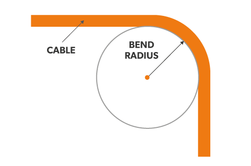
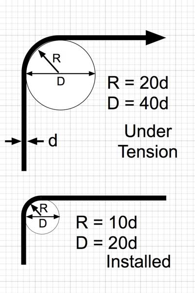
Bend radius, which is measured to the inside curvature, is the minimum radius one can bend a fiber optic Cable without kinking it, damaging it, or shortening its life. The smaller the bend radius, the greater the material flexibility (as the radius of curvature decreases, the curvature increases). A Minimum Bend Radius is the radius below which an Optical Fiber or fiber-optic cable should not be bent. Larger radii bends are easier to pull, and put less Strain on the cable being pulled.
The minimum bend radius is of particular importance in the handling of fiber-optic Cables and varies with different cable designs. The manufacturer should specify the minimum radius to which the cable may safely be bent during installation, and for the long term. The former is somewhat shorter than the latter. The minimum bend radius is in general also a function of tensile stresses during installation, while being bent around a sheave while the fiber or cable is under tension. If no minimum bend radius is specified, one is usually safe in assuming a minimum long-term low-stress radius not less than 15 times the cable diameter.

In this article, we outline important technical topics related to wire rope. This information has been sourced from and approved by Bridon American. Use the outline to skip to specific sections:
Any assembly of steel wires spun into a helical formation, either as a strand or wire rope (when subjected to a tensile load) can extend in three separate phases, depending on the magnitude of the applied load.
At the commencement of loading a new rope, extension is created by the bedding down of the assembled wires with a corresponding reduction in overall diameter. This reduction in diameter is accommodated by a lengthening of the helical lay. When sufficiently large bearing areas have been generated on adjacent wires to withstand the circumferential compressive loads, this mechanically created extension ceases and the extension in Phase 2 commences. The Initial Extension of any rope cannot be accurately determined by calculation and has no elastic properties.
The practical value of this characteristic depends upon many factors, the most important being the type and construction of rope, the range of loads and the number and frequency of the cycles of operation. It is not possible to quote exact values for the various constructions of rope in use, but the following approximate values may be employed to give reasonably accurate results.
Following Phase 1, the rope extends in a manner which complies approximately with Hookes Law (stress is proportional to strain) until the limit of proportionality or elastic limit is reached.
It is important to note that wire ropes do not possess a well defined Young’s Modulus of Elasticity, but an ‘apparent’ Modulus of Elasticity can be determined between two fixed loads.
By using the values given, it is possible to make a reasonable estimate of elastic extension, but if greater accuracy is required, it is advisable to carry out a modulus test on an actual sample of the rope. As rope users will find it difficult to calculate the actual metallic steel area, the values can be found in the Wire Rope Users Manual or obtained from Bridon Engineering.
The permanent, non-elastic extension of the steel caused by tensile loads exceeding the yield point of the material. If the load exceeds the Limit of Proportionality, the rate of extension will accelerate as the load is increased until a loading is reached at which continuous extension will commence, causing the wire rope to fracture without any further increase of load.
The coefficient of linear expansion (∝) of steel wire rope is (6.94 x 10⁻⁶ per °F) and therefore the change in length of 1 foot of rope produced by a temperature change of t (°F) would be:
Example: What will be the total elongation of a 200 ft. length of 1-1/8″ diameter Blue Strand 6 x 41 IWRC wire rope at a tension of 20,000 Ibs. and with an increase in temperature of 20°F?
In addition to bending stresses experienced by wire ropes operating over sheaves or pulleys, ropes are also subjected to radial pressure as they make contact with the sheave. This pressure sets up shearing stresses in the wires, distorts the rope’s structure and affects the rate of wear of the sheave grooves. When a rope passes over a sheave, the load on the sheave bearing results from the tension in the rope and the angle of rope contact. It is independent of the diameter of the sheave.
Assuming that the rope is supported in a well fitting groove, then the pressure between the rope and the groove is dependent upon the rope tension and diameter, but is independent of the arc of contact.
It must be realized that this method of estimation of pressure assumes that the area of contact of the rope in the groove is on the full rope diameter, whereas in fact only the crowns of the outer wires are actually in contact with the groove. It is estimated that the local pressures at these contact points may be as high as five times those calculated. If the pressure is high, the compressive strength of the material in the groove may be insufficient to prevent excessive wear and indentation, and this in turn will damage the outer wires of the rope and effect its working life.
As with bending stresses, stresses due to radial pressure increase as the diameter of the sheave decreases. Although high bending stresses generally call for the use of flexible rope constructions having relatively small diameter outer wires, these have less ability to withstand heavy pressures than do the larger wires in the less flexible constructions. If the calculated pressures are too high for the particular material chosen for the sheaves or drums or indentations are being experienced, consideration should be given to an increase in sheave or drum diameter. Such a modification would not only reduce the groove pressure, but would also improve the fatigue life of the rope.
The pressure of the rope against the sheave also causes distortion and flattening of the rope structure. This can be controlled by using sheaves with the correct groove profile, which, for general purposes, suggests a recommended groove diameter of nominal rope diameter +6%. The profile at the bottom of the groove should be circular over an angle of approximately 120° and the angle of flare between the sides of the sheave should be approximately 52°.
Bend fatigue testing of ropes usually consists of cycling a length of rope over a sheave while the rope is under a constant tension. As part of their ongoing development program, Bridon has tested literally thousands of ropes in this manner over the years on their own in-house design bend testing equipment.
Through this work, Bridon has been able to compare the effects of rope construction, tensile strength, lay direction, sheave size, groove profile and tensile loading on bend fatigue performance under ideal operating conditions. At the same time it has been possible to compare rope life to discard criteria (e.g. as laid down in ISO 4309) with that to complete failure of the rope, i.e. to the point where the rope has been unable to sustain the load any longer. As part of the exercise, it has also been possible to establish the residual breaking strength of the rope at discard level of deterioration.
What needs to be recognized, however, is that very few ropes operate under these controlled operating conditions, making it very difficult to use this base information when attempting to predict rope life under other conditions. Other influencing factors, such as dynamic loading, differential loads in the cycle, fleet angle, reeving arrangement, type of spooling on the drum, change in rope direction, sheave alignment, sheave size and groove profile, can have an equally dramatic effect on rope performance.
If designers or operators of equipment are seeking optimum rope performance or regard bending fatigue life as a key factor in the operation of equipment, such information can be provided by Bridon for guidance purposes.
Wire ropes are manufactured slightly larger than the nominal diameter. The maximum allowable oversize tolerances provided by industry standards are shown in the following table:
Under certain circumstances it may be necessary to use a swivel in a lifting system to prevent rotation of the load. This is typically done for employee safety considerations. It is possible however, that the use of a swivel will have an adverse affect on rope performance and may, in some cases, damage the wire rope.
There are many types of accessories available that incorporate different types and degrees of rotation- preventing swivels. The swivel may be either an independent accessory or an integral part of a lifting device, such as a crane block with a swivel hook. A typical independent accessory is a ball bearing anti-friction swivel. There are also headache balls with swivel hooks.
The type of swivel that causes the most concern from the standpoint of the wire rope is the independent anti-friction swivel that attaches directly to the rope. The purpose of using a swivel in a lifting system is to prevent rotation of the load. This then allows the wire rope to rotate. Excessive rope rotation can damage a wire rope.
To assist in determining whether or not a swivel should be used in the lifting system, the following recommendations should be considered. It must also be recognized that the rotation characteristics of different types and constructions of wire rope vary considerably. The following types and constructions of wire rope are grouped according to their rotation characteristics.
These rope constructions will rotate excessively with one end free to rotate, and the rope will unlay and distort and be easily damaged with a loss of rope breaking force.Blue Strand 6 x 19 and 6 x 36 Class Lang Lay
Wire rope constructions having high rotation characteristics when used in single part reeving may require a swivel in the system to prevent rotation in certain operating conditions. However, this should be done only when employee safety is the issue.
These rope constructions, when used in a reeving system with one end free to rotate, will have a high level of rotation. This will cause the rope to unlay and, to some degree, distortion of the rope will occur.Blue Strand 6 x 19 and 6 x 36—Class Regular Lay
The ropes in this Group are designed with an inner rope that is laid in the opposite direction to the outer strands to provide a medium resistance to rotation. Ropes with medium rotation characteristics are used with a swivel in single part reeving applications. However, a swivel is not recommended for multiple part hoisting applications or in any application where the swivel is not necessary for safety reasons. If it is necessary to use a swivel, the rope must be operating at a design factor of 5 or greater, must not be shock loaded and must be inspected daily by a qualified person for distortion.
It should be noted that if a swivel is used on conjunction with Group 3a ropes, rope service life might be reduced due to increased internal wear between the outer strands and the inner rope.Group 3aEndurance 8RR Rotation Resistant
Wire ropes having low rotation characteristics used in either single or multiple part reeving may be used with a swivel. The reason for this is that the ropes will exhibit very little, if any, rotation when used at the proper design factor. Application parameters, such as a fleet angle, may induce turn into a wire rope that can be relieved by the use of a swivel. However, if the application does not induce any turn into the rope, or if a swivel is not beneficial to the performance of the rope, the swivel may not be necessary.Endurance 35 LS
Fleet angle is usually defined as the included angle between two lines: one which extends from a fixed sheave to the flange of a drum, and the other which extends from the same fixed sheave to the drum in a line perpendicular to the axis of the drum (see illustration).
If the drum incorporates helical grooving, the helix angle of the groove needs to be added or subtracted from the fleet angle as described above to determine the actual fleet angle experienced by the rope.
When spooling rope onto a drum, it is generally recommended that the fleet angle is limited to between 0.5° and 2.5°. If the fleet angle is too small, i.e. less than 0.5°, the rope will tend to pile up at the drum flange and fail to return across the drum. In this situation, the problem may be alleviated by introducing a ‘kicker’ device or by increasing the fleet angle through the introduction of a sheave or spooling mechanism.
If the rope is allowed to pile up, it will eventually roll away from the flange, creating a shock load in both the rope and the structure of the mechanism, an undesirable and unsafe operating condition.
Excessively high fleet angles will return the rope across the drum prematurely, creating gaps between wraps of rope close to the flanges, as well as increasing the pressure on the rope at the cross-over positions.
Even where helical grooving is provided, large fleet angles will inevitably result in localized areas of mechanical damage as the wires ‘pluck’ against each other. This is often referred to as ‘interference’, but the amount can be reduced by selecting a Langs lay rope if the reeving allows. The “interference” effect can also be reduced by employing a Dyform rope, which offers a much smoother exterior surface than conventional rope constructions.
Where a fleet angle exists as the rope enters a sheave, it initially makes contact with the sheave flange. As the rope continues to pass through the sheave it moves down the flange until it sits in the bottom of the groove. In doing so, even when under tension, the rope will actually roll, as well as slide. As a result of the rolling action, the rope is twisted, i.e. turn is induced into or out of the rope, either shortening or lengthening the lay length of the outer layer of strands. As the fleet angle increases, so does the amount of twist.
To reduce the amount of twist to an acceptable level, the fleet angle should be limited to 2.5° for grooved drums and 1.5° for plain drums and when using Rotation Resistant, ropes the fleet angle should be limited to 1.5°.
However, for some crane and hoist applications, it is recognized that for practical reasons. It is not always possible to comply with these general recommendations, in which case, the rope life could be affected.
The problem of torsional instability in crane hoist ropes would not exist if the ropes could be perfectly torque balanced under load. The torque generated in a wire rope under load is usually directly related to the applied load by a constant ‘torque factor’. For a given rope construction, the torque factor can be expressed as a proportion of the rope diameter and this has been done below.
Variation with rope construction is relatively small and hence the scope for dramatically changing the stability of a hoisting system is limited. Nevertheless, the choice of the correct rope can have a deciding influence, especially in systems which are operating close to the critical limit. It should be noted that the rope torque referred to here is purely that due to tensile loading. No account is taken of the possible residual torque due, for example, to rope manufacture or installation procedures.
Torsional Stability and the Cabling Graph are two methods which can be used to determine torsional stability or the tendency of the rope to cable. The torque factors quoted are approximate maximum values for the particular constructions. To calculate the torque value for a particular rope size, multiply by the nominal rope diameter.
The torsional characteristics of wire rope will have the effect of causing angular displacement of a sheave block when used in multi-fall reeving arrangements. The formula below gives a good approximation under such arrangements.
When the angular displacement of the sheave block exceeds 90° (sin 0 = 1) torsional instability results and ‘cabling’ of the reeving will occur. Therefore, the test for stability of any particular reeving can be expressed as:
The preceding equations are all relative to a simple two part reeving. For more complex systems, a similar approach may be used if account is taken of the different spacings of the ropes.
The equations assume that rope is torque-free in the noload condition, therefore, induced torque during or immediately after installation will adversely influence the calculated effect.
The above data assumes a constant torque value which is a valid assumption for a new rope. Wear and usage can have a significant effect on the torque value, but practical work shows that under such circumstances, the torque value will diminish, thus improving the stability of the arrangement. Some arrangements may be of such complexity that the evaluation demands a computer study.
Assuming a pedestal crane working on two falls is roped with 20mm diameter DYFORM 34LR and the bottom block carries a sheave of 360mm diameter with the falls parallel:
If the rope is new (worst condition) and no account is taken of block weight and friction then angular displacement for a height of lift of 30 meters is given by:
From the crane designer’s viewpoint, a safety factor against ‘cabling’ should be recognized (angular displacement limited at 30°), hence the practical height of lift is approximately 106.5 meters.
Field research jointly conducted by the Wire Rope Technical Board and the Power Crane and Shovel Association has shown that cabling of the rope parts in a multiple part reeved hoisting arrangement is controlled by several factors. The following calculations and graphs can be used to determine when and if cabling will occur on multiple part reeved hoisting arrangements.
Various constructions of rope shown on the graph indicate the limited conditions for torsional stability with the angular displacement of the hoist block to a maximum of 90 degrees. When the operating conditions for a particular installation give a resultant above the appropriate band, then cabling of the falls will most likely occur. If the operating conditions give a resultant below any particular band, the cabling of the falls will most likely not occur. If the operating conditions for any particular installation fall within the band, cabling is unpredictable.

The radius of the bending pipe can be hard to measure in field. In practice a rope or chain may be tied to the end of the pipe and the end is pulled until deflection is achieved.
Fortunately, it is not necessary to make use of our engineering team to take advantage of our engineering expertise. Our engineering team has applied their years of industry experience to develop design resource documentation for each of our product lines. By sharing their knowledge and experience in these easy-to-use guides, our engineers empower your team to undertake the specification process independently of the manufacturing process. Details about coatings, tolerances, installation and assembly, and the unique design considerations for each product line are concisely presented. Each guide includes all of the critical cable and cable assembly information to assist your team in the specification of your cabling project.
There are many common, everyday applications that use efficient and reliable Cablecraft controls. These applications include automotive seat releases, lawn mower throttle controls, and airplane seat back controls. Some uses of controls are obvious and visible, while others are not. Simple and lightweight controls for dependable...
The Cablecraft “Cycle-Flex™ Design Guide” is a comprehensive reference of design considerations for the specification of Cycle-Flex miniature cables. Some of the topics covered in this Guide include:What is Cycle-Flex™ cable
The Cablecraft “General Applications / Safety & Restraint Design Guide” is a comprehensive reference of design considerations for the specification of general use cables and cable assemblies. Some of the topics covered in this Guide include:How wire rope and cables are fabricated


 8613371530291