
what is the safety factor of wire rope sling factory

Wire ropes are essential for safety purposes on construction sites and industrial workplaces. They are used to secure and transport extremely heavy pieces of equipment – so they must be strong enough to withstand substantial loads. This is why the wire rope safety factor is crucial.
You may have heard that it is always recommended to use wire ropes or slings with a higher breaking strength than the actual load. For instance, say that you need to move 50,000 lbs. with an overhead crane. You should generally use equipment with a working load limit that is rated for weight at least five times higher – or 250,000 lbs. in this case.
This recommendation is all thanks to the wire rope safety factor. This calculation is designed to help you determine important numbers, such as the minimum breaking strength and the working load limit of a wire rope.
The safety factor is a measurement of how strong of a force a wire rope can withstand before it breaks. It is commonly stated as a ratio, such as 5:1. This means that the wire rope can hold five times their Safe Work Load (SWL) before it will break.
So, if a 5:1 wire rope’s SWL is 10,000 lbs., the safety factor is 50,000 lbs. However, you would never want to place a load near 50,000 lbs. for wire rope safety reasons.
The safety factor rating of a wire rope is the calculation of the Minimum Break Strength (MBS) or the Minimum Breaking Load (MBL) compared to the highest absolute maximum load limit. It is crucial to use a wire rope with a high ratio to account for factors that could influence the weight of the load.
The Safe Working Load (SWL) is a measurement that is required by law to be clearly marked on all lifting devices – including hoists, lifting machines, and tackles. However, this is not visibly listed on wire ropes, so it is important to understand what this term means and how to calculate it.
The safe working load will change depending on the diameter of the wire rope and its weight per foot. Of course, the smaller the wire rope is, the lower its SWL will be. The SWL also changes depending on the safety factor ratio.
The margin of safety for wire ropes accounts for any unexpected extra loads to ensure the utmost safety for everyone involved. Every year there aredue to overhead crane accidents. Many of these deaths occur when a heavy load is dropped because the weight load limit was not properly calculated and the wire rope broke or slipped.
The margin of safety is a hazard control calculation that essentially accounts for worst-case scenarios. For instance, what if a strong gust of wind were to blow while a crane was lifting a load? Or what if the brakes slipped and the load dropped several feet unexpectedly? This is certainly a wire rope safety factor that must be considered.
Themargin of safety(also referred to as the factor of safety) measures the ultimate load or stress divided by theallowablestress. This helps to account for the applied tensile forces and stress thatcouldbe applied to the rope, causing it to inch closer to the breaking strength limit.
A proof test must be conducted on a wire rope or any other piece of rigging equipment before it is used for the first time.that a sample of a wire rope must be tested to ensure that it can safely hold one-fifth of the breaking load limit. The proof test ensures that the wire rope is not defective and can withstand the minimum weight load limit.
First, the wire rope and other lifting accessories (such as hooks or slings) are set up as needed for the particular task. Then weight or force is slowly added until it reaches the maximum allowable working load limit.
Some wire rope distributors will conduct proof loading tests before you purchase them. Be sure to investigate the criteria of these tests before purchasing, as some testing factors may need to be changed depending on your requirements.
When purchasing wire ropes for overhead lifting or other heavy-duty applications, understanding the safety dynamics and limits is critical. These terms can get confusing, but all of thesefactors serve an important purpose.
Our company has served as a wire rope distributor and industrial hardware supplier for many years. We know all there is to know about safety factors. We will help you find the exact wire ropes that will meet your requirements, no matter what project you have in mind.
Original equipment wire rope and replacement wire rope must be selected and installed in accordance with the requirements of this section. Selection of replacement wire rope must be in accordance with the recommendations of the wire rope manufacturer, the equipment manufacturer, or a qualified person.
Wire rope design criteria: Wire rope (other than rotation resistant rope) must comply with either Option (1) or Option (2) of this section, as follows:
Option (1). Wire rope must comply with section 5-1.7.1 of ASME B30.5-2004 (incorporated by reference, see § 1926.6) except that section"s paragraph (c) must not apply.
Option (2). Wire rope must be designed to have, in relation to the equipment"s rated capacity, a sufficient minimum breaking force and design factor so that compliance with the applicable inspection provisions in § 1926.1413 will be an effective means of preventing sudden rope failure.
Type I rotation resistant wire rope ("Type I"). Type I rotation resistant rope is stranded rope constructed to have little or no tendency to rotate or, if guided, transmits little or no torque. It has at least 15 outer strands and comprises an assembly of at least three layers of strands laid helically over a center in two operations. The direction of lay of the outer strands is opposite to that of the underlying layer.
Type II rotation resistant wire rope ("Type II"). Type II rotation resistant rope is stranded rope constructed to have significant resistance to rotation. It has at least 10 outer strands and comprises an assembly of two or more layers of strands laid helically over a center in two or three operations. The direction of lay of the outer strands is opposite to that of the underlying layer.
Type III rotation resistant wire rope ("Type III"). Type III rotation resistant rope is stranded rope constructed to have limited resistance to rotation. It has no more than nine outer strands, and comprises an assembly of two layers of strands laid helically over a center in two operations. The direction of lay of the outer strands is opposite to that of the underlying layer.
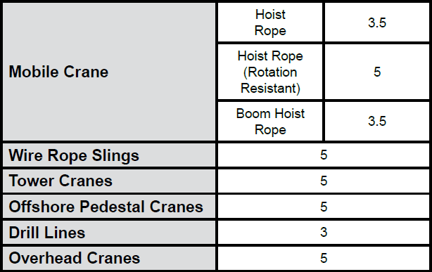
Type I must have an operating design factor of no less than 5, except where the wire rope manufacturer and the equipment manufacturer approves the design factor, in writing.
When Types II and III with an operating design factor of less than 5 are used (for non-duty cycle, non-repetitive lifts), the following requirements must be met for each lifting operation:
A qualified person must inspect the rope in accordance with § 1926.1413(a). The rope must be used only if the qualified person determines that there are no deficiencies constituting a hazard. In making this determination, more than one broken wire in any one rope lay must be considered a hazard.
Each lift made under § 1926.1414(e)(3) must be recorded in the monthly and annual inspection documents. Such prior uses must be considered by the qualified person in determining whether to use the rope again.
Rotation resistant ropes may be used as boom hoist reeving when load hoists are used as boom hoists for attachments such as luffing attachments or boom and mast attachment systems. Under these conditions, all of the following requirements must be met:
The requirements in ASME B30.5-2004 sections 5-1.3.2(a), (a)(2) through (a)(4), (b) and (d) (incorporated by reference, see § 1926.6) except that the minimum pitch diameter for sheaves used in multiple rope reeving is 18 times the nominal diameter of the rope used (instead of the value of 16 specified in section 5-1.3.2(d)).
The operating design factor for these ropes must be the total minimum breaking force of all parts of rope in the system divided by the load imposed on the rope system when supporting the static weights of the structure and the load within the equipment"s rated capacity.
Wire rope clips used in conjunction with wedge sockets must be attached to the unloaded dead end of the rope only, except that the use of devices specifically designed for dead-ending rope in a wedge socket is permitted.
Prior to cutting a wire rope, seizings must be placed on each side of the point to be cut. The length and number of seizings must be in accordance with the wire rope manufacturer"s instructions.

Wire rope is often used in slings because of its strength, durability, abrasion resistance and ability to conform to the shape of the loads on which it is used. In addition, wire rope slings are able to lift hot materials.
Wire rope used in slings can be made of ropes with either Independent Wire Rope Core (IWRC) or a fiber-core. It should be noted that a sling manufactured with a fiber-core is usually more flexible but is less resistant to environmental damage. Conversely, a core that is made of a wire rope strand tends to have greater strength and is more resistant to heat damage.
Wire rope may be manufactured using different rope lays. The lay of a wire rope describes the direction the wires and strands are twisted during the construction of the rope. Most wire rope is right lay, regular lay. This type of rope has the widest range of applications. Wire rope slings may be made of other wire rope lays at the recommendation of the sling manufacturer or a qualified person.
Wire rope slings are made from various grades of wire rope, but the most common grades in use are Extra Improved Plow Steel (EIPS) and Extra Extra Improved Plow Steel (EEIPS). These wire ropes are manufactured and tested in accordance with ASTM guidelines. If other grades of wire rope are used, use them in accordance with the manufacturer"s recommendations and guidance.
When selecting a wire rope sling to give the best service, consider four characteristics: strength, ability to bend without distortion, ability to withstand abrasive wear, and ability to withstand abuse.
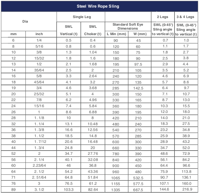
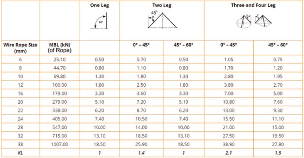
Rated loads (capacities) for single-leg vertical, choker, basket hitches, and two-, three-, and four-leg bridle slings for specific grades of wire rope slings are as shown in Tables 7 through 15.
Rated loads for a sling in a choker hitch are the values shown in Table 7, 9, 11, 13, 14, or 15, provided that the angle of the choke is 120 degrees or more (Fig. 2). Use the values in Fig. 2 or those from the sling manufacturer or a qualified person for angles of choke less than 120 degrees.
Ensure that slings made of rope with 6×19 and 6x37 classifications and cable slings have a minimum clear length of rope 10 times the component rope diameter between splices, sleeves, or end fittings unless approved by a qualified person,
Ensure that braided slings have a minimum clear length of rope 40 times the component rope diameter between the loops or end fittings unless approved by a qualified person,
Ensure that grommets and endless slings have a minimum circumferential length of 96 times the body diameter of the grommet or endless sling unless approved by a qualified person, and
Perform welding of handles or other accessories to end attachments, except covers to thimbles, before assembly of the sling. Ensure that welded end attachments are proof tested by the manufacturer or a qualified person. Retain the certificates of proof test and make them available for examination.
Do not use wire rope clips to fabricate wire rope slings, except where the application precludes the use of prefabricated slings and where the sling is designed for the specific application by a qualified person,
Although OSHA"s sling standard does not require you to make and maintain records of inspections, the ASME standard contains provisions on inspection records.[3]
Use damaged slings only after they are repaired, reconditioned, and proof tested by the sling manufacturer or a qualified person using the following criteria:
Ensure that wire rope slings have suitable characteristics for the type of load, hitch, and environment in which they will be used and that they are not used with loads in excess of the rated load capacities described in the appropriate tables. When D/d ratios (Fig. 4) are smaller than those listed in the tables, consult the sling manufacturer. Follow other safe operating practices, including:
Ensure that multiple-leg slings are selected according to Tables 7 through 15 when used at the specific angles given in the tables. Ensure that operations at other angles are limited to the rated load of the next lower angle given in the tables or calculated by a qualified person,
When D/d ratios (see Fig. 6) smaller than those cited in the tables are necessary, ensure that the rated load of the sling is decreased. Consult the sling manufacturer for specific data or refer to the WRTB (Wire Rope Technical Board) Wire Rope Sling Users Manual, and
Ensure that all portions of the human body are kept away from the areas between the sling and the load and between the sling and the crane or hoist hook,
When using a basket hitch, ensure that the legs of the sling contain or support the load from the sides, above the center of gravity, so that the load remains under control,
Ensure that the load applied to the hook is centered in the base (bowl) of the hook to prevent point loading on the hook, unless the hook is designed for point loading,
Before initial use, ensure that all new swaged-socket, poured-socket, turnback-eye, mechanical joint grommets, and endless wire rope slings are proof tested by the sling manufacturer or a qualified person.
Permanently remove from service fiber-core wire rope slings of any grade if they are exposed to temperatures in excess of 180 degrees F (82 degrees C).
Follow the recommendations of the sling manufacturer when you use metallic-core wire rope slings of any grade at temperatures above 400 degrees F (204 degrees C) or below minus 40 degrees F (minus 40 degrees C).
Safe Working Load (SWL) is the limiting safety factor to lift and carry any load safely. It must be clearly marked on any lifting device (hoist, lifts, lifting machines, and lifting tackles).
“No lifting machine and no chain, rope or lifting tackle shall, except for the purpose of the test, be loaded beyond the safe working load which shall be plainly marked and duly entered in the prescribed register, and where this is not practicable, a table showing the safe working loads of every kind and size of lifting machine or chain, rope or lifting tackle in use shall be displayed in prominent positions on the premises”
Where the safe working load may be varied by the raising or lowering of the jib, a table indicating the SWL at the corresponding indication of the jib or corresponding radii of the load shall be attached with the jib-crane.
A table showing the SWL (Safe Working Load) of every kind and size of chain, rope, or lifting tackle in use, and in case of multiple slings, the SWLat different angles of the legs, shall be posted in the storeroom.
Lifting equipment should have a tally plate indicating the Safe Working Load. The tally plate also indicates the identification number which can be mentioned in the test certificate held by the user. It should also indicate the date of the last inspection.
Safe Working Load (SWL) of any mobile crane depends on the operator’s skill, condition of the ground, boom length, the radius of rotation while lifting the load, the inclination of the boom to the vertical and outrigger blocked or free.
Safe Working Load is generally tabulated in the load chart of the crane. Sometimes, it is de-rated(decreased) due to defect in welding, bend in angle, bracing, etc., and condition of clutch, brake, etc. Modern cranes give a digital display of SWL, angle indicator, boom limit switch, and alarm for exceeding load.
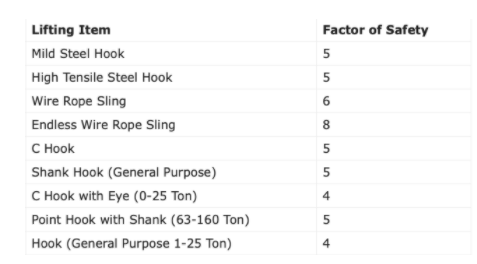
The factor of the safety (Safety Factor) of fiber ropes varies from 6 to 12 mm depending on the conditions of use. fiber rope less than 12 mm dia should not be used for a sling or apart of a lifting appliance. Their factor of safety (FS) varies with diameter. The factor of Safety for the hook, wire rope sling, chain, fiber rope, and belt are given in the table below:
Proof testing is the application of a load greater than the SWL (Safe Working Load) to detect defective workmanship, faulty weld or other inherent weaknesses. It is not a means to assess the SWLwhich should only be done by calculations and checked where necessary by suitable tests on samples.
The proof test is required as a part of ‘thorough examination’ u/r 60(1) of GFRand no lifting machine or tackle should be used for the first time without this proof test.
In general, the proof load applied to chains, rings, hooks, shackles, and similar gear is twice the SWL. It should be just under the yield stress for the material.
Chain, ring, hook, shackles, swivel, sling, individual components of the hoist, wire rope, chain, pulleys, hooks, eye bolts, pins, axles, bearings, turnbuckles & ringing screws.2 SWL
After the above proof test, the parts are to be examined thoroughly by a competent person for signs of cracks, fatigue, deformation, permanent stretch, etc.

Have you wondered why rigging experts always suggest a sling that has a significantly higher breaking strength than the actual weight of the load you are lifting? The manufacturers know that the rigging used in overhead applications need to have room for error. This is known as the Safety Factor.
Northern Strands manufactures wire rope slings rated up to 36,000 lbs and sells round synthetic slings that are rated up to 140,000 lb capacity. This capacity is the Working Load Limit of the sling, which is the maximum amount of weight or force that the sling"s user is allowed to put on the sling. Note: These slings do not break at the working load limit. These slings are designed with a safety factor of 5:1. This means that 5 times as much force as the working load limit has to be applied to the sling before it potentially fails. This means the wire rope slings have a Breaking Strength of up to 180,000 lbs and the round synthetic slings can withhold up to 700,000 lbs.
Wear - Working load limits are based on slings in brand new condition and a safety factor can help account for normal wear and tear until it is deemed unfit for further use.
Uneven loading - Slings are made up of either wires or fibers that must all share the weight of the load evenly. If any situation arises where the sling is bent or wrapped around an object, there is potential that some of the wires or fibers will be taking on a greater share of the load than others.
Visit Northern Strands website to use the sling tension calculator. The Northern Strands Sling Calculator has been designed to assist you in selecting slings with enough load carrying capacity for your lifting applications. It is your responsibility to assure that the slings you use are appropriate for your application. http://www.northernstrands.com/sling-calculator.aspx

This is a guide to factors of safety in circus rigging covering the basic concepts with a discussion on different ways to determine the forces applied.
This document is a draft for review and NOT to be put into use. Please send feedback to mark@aerialedge.co.uk. The document was created with input from members of the Circus Rigging and Safety Forum and based on UK and EU regulations
For lifting equipment, a manufacturer will repeatedly test their equipment to failure enough times to work out at what load their equipment is likely to break at. They will then add a factor of safety to determine the maximum load that can safely be placed on the equipment when in use.
The factor of safety is written as a ratio and used to determine what forces equipment can safely support. As an easy example, if your equipment needs to be strong enough to lift 1,000kg, and your factor of safety is 4:1, you should make sure that it is strong enough to lift 4,000kg
The Minimum Breaking Load (MBL) is the force a piece of equipment can be exposed to above which it is statistically likely to break. One method to determine the MBL is by testing equipment to destruction multiple times. This allows the manufacturer to collect sufficient data to understand the minimum load it takes to break the equipment 99.7% of the time (using 3-sigma a statistical method to calculate probability).
This testing makes no allowance for the reduction in strength made by terminations such as knots or splices in a rope or wire rope. With forged metal items tests will be conducted with the load applied in the designed axis, the angle along which the equipment was designed to be used, for example on the long axis of a karabiner or an oval ring.
The Minimum Breaking Load (MBL), also known as the Minimum Breaking Strain (MBS), is typically marked in kilonewtons (kN) because it is a measurement of force rather than mass.
The Minimum Breaking Load is the figure that you will see typically see marked on Personal Protective Equipment (PPE) and climbing equipment such as climbing slings, karabiners, pulleys, and swivels.
The Minimum Breaking Load does NOT include a factor of safety and it does NOT mean it is safe to apply forces on the equipment up to this figure. This is where the Working Load Limit comes in.
The Working Load Limit (WLL) is used in the lifting industry to show what the maximum load equipment in normal use can be exposed to. This figure is marked on the equipment by the manufacturer and does include a factor of safety. This was originally specified by the EU Machinery Directive.
The Factor of Safety specified for forged (metal) equipment like shackles and chains is 4:1, steel wire rope is 5:1, and ropes and slings made from artificial fibres is 7:1. In the UK this is made law by the Supply of Machinery (Safety) Regulations 2008.
This means a CE or UKCA marked shackle, ring, or eyebolt with a marked WLL of 1 tonne has an MBL of at least 4 tonnes. Any lifting operation will produce more force than just the measured mass of the object being lifted.
The factor of safety is intended to allow for the vagaries of lifting operations, such as wear and tear, shock loads, or aggressive movements. You can therefore place a load of up to 1 tonne on it with confidence because it will not break through overload until a load of at least 4 tonnes is placed on it. Everyone can sleep at night.
The manufacturer calculates the Working Load Limit by dividing the Minimum Breaking Load by a Factor of Safety (FOS). The Working Load Limit must be marked in kilograms (kg) in Europe and the UK.
In our first example, let’s say we have a forged steel bow shackle with a WLL of 1000kgs. If it is UKCA/CE marked, it will usually have a FOS of 6:1. This means the MBL of the shackle is WLL x 6, i.e., 6000 kgs.
In our second example, we have a round sling with a marked WLL of 1 tonne. Artificial fibre slings must use a FOS of 7:1 therefore we know the MBL of the sling is 7 tonnes when new. WLL of 1000kg x FOS of 7 = MBL of 7000kg.
Around the world legal requirements vary. The factor of safety required by law in the EU and UK for lifting equipment put on the market is between 4:1 and 7:1 depending on the material of manufacture. When lifting equipment that is not designed to lift people is used for lifting people in the UK and the EU the factor of safety normally used for lifting must be doubled.
LOLER 1998 (The UK’s ‘Lifting Operations and Lifting Equipment Regulations’ 1998) Regulation 5 section 157 states “Equipment used for the lifting of people should have a factor of safety relating to its strength of at least twice that required for general lifting operations. This is the arithmetic ratio between the minimum breaking or failure load and the maximum working load marked on the equipment.”
As an example, for a shackle used to lift people, we must calculate the force we will apply to the equipment. This includes the weight and movement of the performer(s) and the dynamic effects associated with the speed of the lift. We then compare this with the MBL on the declaration of conformity. The factor for such equipment is normally 4:1 so we double that to 8:1. If we know that the act produces a maximum force of 1.2kN (120kgs) at that shackle, its MBL must be at least 8 x 1.2kN = 9.6kN.
Acrobatic performers may generate forces much greater than their own body weight; this could exceed a factor of 5 times their body weight. Using a load cell, a device used for measuring force, we have recorded forces of up to eight times the bodyweight of professional artists on certain types of equipment.
Dynamic loads are created by objects in motion. In our case, that is our performer(s). An artist suspended in a harness or performing on circus equipment creates a dynamic load of variable force, which could be called a ‘variable action’.
Static loads are loads where the forces acting on them are constant over time - perhaps better thought of as a ‘permanent action’. In other words, they do not move and are unlikely to be found in acrobatic apparatus.
One term of note from our above definitions is that of ‘normal use’. What is normal use? In lifting operations, usually lifting inanimate objects. The WLL as shown on most equipment is NOT designed for human loads so when we design rigging solutions the ‘competent person’ who is designing the system will have to apply some additional calculations.
They will need a good understanding of the normal use of the equipment and have good working knowledge about the actual forces that are intended to be applied to the equipment.
Manufacturers’ use cases are unlikely to include acrobatics. When designing rigging for a specific application, we need to look carefully at that equipment and ensure that it is strong enough for how we want to use it.
- And crucially at what speed(s)? It is the speed of starting and stopping a lifting or falling motion that creates the extra force as we work against the force of gravity.
- What the equipment is connected to (materials and diameters of other components like hoop/trapeze tags, fibre elements, thimbles in eyes, other connectors/plates/eyebolts)
This is not an exhaustive list of considerations, and each application will be different. So, plenty of experience and an attitude of curiosity is required.
The MBL of the equipment won’t change but we will need to revise the factor of safety to create our own version of a WLL. This we can call either a Safe Working Load (SWL) or a Design Load to differentiate it from the manufacturer’s markings and to denote it applies to a specific application for which the equipment is being used.
With dynamic loads, the forces applied to them are changing over time, to determine what equipment to use and how strong our rigging point should be we need to be able to work out what the maximum dynamic force is for our specific application. We can call this the Peak Load. This we are defining as the maximum momentary peak load when the activity is measured.
There are several ways to work out what forces are placed on a piece of equipment during a performance or in a class. We could look at the biggest drop in an act and use google or some high school physics to work it out. We could include the distance of the drop, the stopping distance, and the bodyweight of the performer.
There are some drawbacks to calculating a load theoretically. You would need to be sure you were using the right formula, that your calculations were correct, and you would also have to understand acrobatic forces well enough to ensure you were calculating the greatest forces in an act. There are many possible ways to calculate the forces involved and there is no clarity on which is the best approach for aerial acrobatics. I would therefore recommend we measure the forces involved.
The surest way to measure a load in circus is to use a device called a load cell, a small but worthwhile investment to understand the forces generated in an act.
Load cells will give a reading based on the amount of force applied to them and can record Peak Loads and chart the varying forces in a graph with force shown on one axis of the graph and time shown on the other.
It is worth considering that some factors may cause an increase in peak load that may not be captured when measuring the activity. An example would be a higher level of adrenalin in the performer during a show causing more powerful movements in each technique. Higher Peak Loads may also occur also if a ‘trick’ goes wrong causing the performer to ‘save’ themselves leading to more aggressive movements.
If we were to collect load cell measurements from multiple tests and put them into a database, we could start to see what forces are generated over a larger pool of artists and students. This would help us more accurately determine rules of thumb for different use cases. We have been doing that for some time within this group and have a database of test data. We would however love to have more people add to the database to cover different arts and equipment as well as more people attempting to reproduce the same results.
In the absence of a known load, we can use a rough rule of thumb by applying a ‘dynamic factor’ where we could estimate the likely dynamic factor for the intended activity and apply that to the bodyweight of the performer. This would require a lot of experience in the forces generated by different acrobatic techniques on different acrobatic equipment. It would also require access to sufficient data to enable us to create the guidelines.
The mass of the performer multiplied by the dynamic factor would now be considered the Design Load in our rigging design. We would then apply a factor of safety to this figure.
The terms ‘static’ and ‘dynamic’ in this section relate to commonly used descriptions in aerial acrobatics where ‘static’ techniques refer to where the equipment itself is hung and relatively static and the dynamic actions are provided by the performer. ‘Dynamic’ techniques usually refer to disciplines like swinging trapeze or flying trapeze. I’ve added the word ‘aerial’ after for clarity.
For low-impact static aerial exercises, we could use a factor of 3:1. Where we multiply the weight of the performer by three to calculate our dynamic factor. This could include static aerial exercises for fitness in a studio or for conditioning or beginner movements such as hanging, sitting, or standing on the aerial equipment (e.g., silks, hammocks, static trapeze, hoop)
Acrobatic routines for fitness or performance increase the Peak Load for example, ‘beating’, which is repeatedly swinging under a piece of equipment, generates significantly more dynamic force. We could use a dynamic factor of 5:1 for techniques like this. Any movement that includes ‘drops’, ‘beats’, or movements that are more aggressive would fit into this category.
Professional performer bodies have been conditioned over time to take loads which would lead to injury in those who are just beginning in aerial arts and can therefore perform techniques that generate greater forces. In addition, certain static aerial equipment with low elasticity in their design and types that can be attached to the performer, such as aerial straps, can help the performer generate much higher peak loads.
Dynamic techniques such as flying trapeze, swinging trapeze, and cloud swing would fall into this category too. This also includes aerial acts that are ‘flown’ or ‘counterweighted’. e.g., straps and similar where the performer is lifted with lifting equipment as part of the performance. In this application, the dynamic effects associated with the speed of lift will need to be included in our design.
Performer flying in theatre, circus, corporate or live events as part of a performance, rehearsal, or training create large and repeated dynamic forces of significance. For performer flying, we could also use a dynamic factor of 10.
In the previous section, we have covered three possible ways to calculate or measure the Peak Load in an act. Once we know the Peak Load generated, we need to then calculate the factors of safety between our dynamic load and the Minimum Breaking Load (MBL) of all the equipment we are using.
As in our previous example, for a shackle when used to lift an acrobatic load, we must compare the force we will apply to the equipment with the MBL on the certificate or declaration of conformity and ensure that it is at least 8 times that load.
CE or UKCA marked karabiners will have an MBL of 22kN or greater, so would be appropriate for lifting people if they are in good condition and rigged appropriately with respect to the application and the environment in which they are used. Equally, it could be said that when the force exceeds 275 kgs, a typical karabiner will not provide 8:1
Only if people are actually being lifted. That is, acts where a performer is being raised and lowered in a harness or on their equipment. It could be argued this is outside the scope of LOLER but using the same principles would be good practice.
In many examples of circus rigging, the equipment is ‘static’ in that the dynamic loads are applied by the performer. Climbing a rope, jumping on a trapeze, or hanging on a hoop cannot be considered ‘lifting’. Therefore, complying with LOLER is not a legal requirement, but PUWER (The Provision and Use of Work Equipment Regulations 1998) will cover its use.
However, taking the same equipment and attaching it to a lifting device/machine/assembly makes the whole thing lifting equipment and then becomes subject to LOLER. Counterweight act rigging uses manual effort and all equipment used can therefore be regarded as lifting equipment and therefore LOLER probably applies.
All equipment in a work scenario would be covered by PUWER regulations. PUWER could apply to a silk hanging in a studio as much as a mat or trampoline so this could be considered a minimum standard for suspended equipment as well as for mats and other work equipment.
Lifting is a more complex scenario when calculating forces over statically hung equipment and the forces applied may well be greater, however, LOLER does cover topics such as forces, factors of safety, and inspection that we would have to reproduce in our risk assessments and method statements to comply with working at height legislation (The Work at Height Regulations 2005).
Applying lifting regulations to suspended equipment may be the easiest way to keep people safe and lower the cost of operations. After all you may end up using the same equipment for counterweighting someone in a show as when training someone in your school. In which case, the items should be marked to show which can be used for lifting. LOLER 1998, Reg 7 (e) and PUWER Reg 23.
Keeping separate equipment for each type of use as well as the extra cost of administration and training may cost more than not applying LOLER to all aerial acrobatic equipment.

SWL, NWL, MBS — all of the acronyms can get very confusing. Don’t fret – we’re here to clear things up when it comes to safe working load limits and the terms associated with it.
Safe Working Load (SWL) sometimes stated as the Normal Working Load (NWL) is the mass or force that a piece of lifting equipment, lifting device or accessory can safely utilize to lift, suspend, or lower a mass without fear of breaking. Usually marked on the equipment by the manufacturer and is often 1/5 of the Minimum Breaking Strength (MBS) although other fractions may be used such as 1/4, 1/6 and 1/10.[1][2][3]
Other synonyms include Working Load Limit (WLL), which is the maximum working load designed by the manufacturer. This load represents a force that is much less than that required to make the lifting equipment fail or yield, also known as the Minimum Breaking Load (MBL). SWL or WLL are calculated by dividing MBL by a safety factor (SF). An example of this would be a chain that has a MBL of 2000 lbf (8.89 kN) would have a SWL or WLL of 400 lbf (1.78 kN) if a safety factor of 5 (5:1, 5 to 1, or 1/5) is used.
Here at Industrial Rope Supply, we are not only committed to providing you with a quality product, but also with all the information needed to insure safety comes first on every job. Have safety questions on a product purchased from us? Contact us today and we’ll be happy to talk you through and/or provide you with the safety materials needed.
The LKING STEEL LIMITED 6 x 37 IWRC (independent wire rope core) single-leg wire rope sling has eye-and-eye endings and a mechanical splice for lifting loads with vertical, choker, or basket configurations in general industry applications. The 6 x 37 IWRC construction contains six strands of wire rope with approximately 37 wires per strand wrapped around a separate 7 X 7 wire rope, which has seven strands with seven wires per strand, in the center of the sling. This construction provides more flexibility than a 6 x 7 or 6 x 19 wire rope sling. The wire rope construction has more abrasion and heat resistance than a web sling. This eye-and-eye sling has an eye, or loop, on both ends, and can be used with vertical, choker, and basket lifting configurations. The eyes are secured with a mechanical (also called Flemish) splice that is stronger than a hand splice. This sling has a minimum D/d ratio of 25 and meets American Society of Mechanical Engineers (ASME) specification B30.9 and Occupational Safety and Health Administration (OSHA) specification 1910.184.
Slings are used to lift heavy objects for industrial applications. Types of slings include web slings, wire rope slings, chain slings, and mesh slings. The appropriate type of sling for an application depends on the strength-to-weight ratio, flexibility and resistance to bending, resistance to abrasion and cutting, resistance to crushing, resistance to stretching, and resistance to high temperatures and other environmental stressors. Slings have one, two, three, or four legs; or a continuous loop of webbing or wire rope. Legs are support branches that extend from a single point at the top of the sling to the item being lifted so the weight of the load is distributed evenly among the branches. Slings have eyes (loops) or alloy steel fittings on the ends.
A vertical lifting configuration connects a crane hook directly to a load with a single, vertical sling, usually by means of a hook. In a choker configuration, the sling wraps entirely around the load, and one loop passes through the other to form a slip noose, or choker. In a basket configuration, the sling passes under the load and both ends of the sling connect to the crane hook. Load capacity is the maximum weight to be lifted in a vertical configuration. The capacity in a choker configuration is approximately equal to the vertical capacity times 0.8. The capacity in a basket configuration, with sling ends at a 90-degree angle, is approximately equal to twice the vertical capacity. Load capacity in a basket configuration decreases if the angle of the sling is less than 90 degrees. For example, a sling with a capacity of 2,000 lb. in a vertical configuration will have an approximate capacity of (2,000)(0.8)=1,600 lb. in a choker configuration and an approximate capacity of (2,000)(2)=4,000 lb. in a basket configuration, if the sling ends are at a 90-degree angle to the load. A wire rope sling"s capacity in a basket configuration applies only when the configuration meets the sling"s minimum D/d ratio, which is the ratio of the diameter of the rope"s curve around the load (D) to the diameter of the sling (d). If the minimum D/d ratio is not met, the capacity of the sling is decreased.
LKING STEEL LIMITED Lifting Technologies manufactures lifting solutions including slings, cranes, and hoists. Founded in 1967, the company is headquartered in Shanghai, China.
B) if the 2legswire rope sling, the hanging points should be on both sides of the goods and the hooks are above the center of gravity of the suspended objects.
C) if it is three legs or four legs wire rope sling, the hanger must be proportioned on the plane around the cargo and the hook is located directly above the center of gravity of the suspended object.
Workers involved in hoisting and rigging must exercise care when selecting and using slings. The selection of slings should be based upon the size and type of the load, and the environmental conditions of the workplace. Slings should be visually inspected before each use to ensure their effectiveness. Improper use of hoisting equipment, including slings, may result in overloading, excessive speed (e.g., taking up slack with a sudden jerk, shock loading), or sudden acceleration or deceleration of equipment.
Factors to consider when choosing the best sling for the job include size, weight, shape, temperature, and sensitivity of the material being moved, and the environmental conditions under which the sling will be used. The following guide may be useful in selecting the appropriate sling:
Alloy steel chains are strong and able to adapt to the shape of the load. Care should be taken when using chain slings because sudden shocks will damage them. This may result in sling failure and possible injury to workers or damage to the load.
Chain slings must be visually inspected prior to use. During the inspection, pay particular attention to any stretching, nicks, gouges, and wear in excess of the allowances made by the manufacturer. These signs indicate that the sling may be unsafe and must be removed from service immediately.
Wire rope is composed of individual wires that have been twisted to form strands. Strands are then twisted to form a wire rope. When wire rope has a fiber core, it is usually more flexible but less resistant to environmental damage. Conversely, wire rope with a core that is made of a wire rope strand tends to have greater strength and is more resistant to heat damage.
When selecting a wire rope sling to give the best service, there are four characteristics to consider: strength, ability to withstand fatigue (e.g., to bend without distortion), ability to withstand abrasive wear, and ability to withstand abuse.
Strength – Strength of wire rope is a function of its size (e.g., diameter of the rope), grade, and construction, and must be sufficient to accommodate the maximum applied load.
Fatigue (Bending without Failure) – Fatigue failure of wire rope is caused by the development of small cracks during small radius bends. The best means for preventing fatigue failure of wire rope slings is to use blocking or padding to increase the bend radius.
Abrasive Wear – The ability of wire rope to withstand abrasion is determined by the size and number of the individual wires used to make up the rope. Smaller wires bend more readily and offer greater flexibility, but are less able to withstand abrasion. Larger wires are less flexible, but withstand abrasion better.
Abuse – Misuse or abuse of wire rope slings will result in their failure long before any other factor. Abuse can lead to serious structural damage, resulting in kinks or bird caging. (In bird caging, the wire rope strands are forcibly untwisted and become spread outwards.) To prevent injuries to workers and prolong the life of the sling, strictly adhered to safe and proper use of wire rope slings.
Wire rope slings must be visually inspected before use. Slings with excessive broken wires, severe corrosion, localized wear, damage to end-fittings (e.g., hooks, rings, links, or collars), or damage to the rope structure (e.g., kinks, bird caging, distortion) must be removed from service and discarded.
Fiber rope and synthetic web slings are used primarily for temporary work, such as construction or painting, and are the best choice for use on expensive loads, highly finished or fragile parts, and delicate equipment.
Fiber rope slings deteriorate on contact with acids and caustics and, therefore, must not be used around these substances. Fiber rope slings that exhibit cuts, gouges, worn surface areas, brittle or discolored fibers, melting, or charring must be discarded. A buildup of powder-like sawdust on the inside of a fiber rope indicates excessive internal wear and that the sling is unsafe. Finally, if the rope fibers separate easily when scratched with a fingernail, it indicates that the sling has suffered some kind of chemical damage and should be discarded.
Shock Absorbency - Regardless of the construction material, shock loading (e.g., excessive speed, rapid acceleration or deceleration) of slings should be minimized. However, it should be noted that synthetic web slings can absorb heavy shocks without damage.
Economy and Long Life – Synthetic web slings have a low initial cost and a long service life. They are unaffected by mildew, rot, or bacteria, resist some chemical action, and have excellent abrasion resistance.
Synthetic web slings must be inspected before use and should be removed from service if found to have acid or caustic burns, melting or charring of any part of the surface, snags, tears, or cuts, broken stitches, distorted fittings, or wear or elongation beyond the manufacturer’s specifications.
The ability to handle materials, whether it be piling, marine timbers or sectional barges is critical on any jobsite. After all, materials must be moved. In short, without materials-handling capability, the marine construction industry would cease to exist.
All employees in marine construction take part in materials handling, to varying degrees. As a result, some employees are injured. In fact, the mishandling of materials is the single largest cause of accidents and injuries in the workplace. Most of these accidents and injuries, as well as the pain and loss of salary and productivity that often result, can be readily avoided. Whenever possible, mechanical means should be used to move materials in order to avoid employee injuries such as muscle pulls, strains, and sprains. In addition, many loads are too heavy and/or bulky to be safely moved manually. Therefore, various types of equipment have been designed specifically to aid in the movement of materials. They include cranes, derricks, hoists, powered industrial trucks, and more.
Because cranes, derricks, and hoists rely upon slings to hold their suspended loads, slings are the most commonly used piece of materials-handling apparatus. This discussion will offer information on the proper selection, maintenance, and use of slings.
The operator must exercise intelligence, care, and common sense in the selection and use of slings. Slings must be selected in accordance with their intended use, based upon the size and type of load and the environmental conditions of the workplace. All slings must be visually inspected before use to ensure that there is no obvious damage.
A well-trained operator can prolong the service life of equipment and reduce costs by avoiding the potentially hazardous effects of overloading equipment, operating it at excessive speeds, taking up slack with a sudden jerk, and suddenly accelerating or decelerating equipment. The operator can look for causes and seek corrections whenever a danger exists. He or she should cooperate with co-workers and supervisors and become a leader in carrying out safety measures – not merely for the good of the equipment and the production schedule, but, more importantly, for the safety of everyone concerned.
The dominant characteristics of a sling are determined by the components of that sling. For example, the strengths and weaknesses of a wire rope sling are essentially the same as the strengths and weaknesses of the wire rope of which it is made.
Slings are generally one of six types: chain, wire rope, metal mesh, natural fiber rope, synthetic fiber rope, or synthetic web. In general, use and inspection procedures tend to place these slings into three groups: chain, wire rope and mesh, and fiber rope web. Each type has its own particular advantages and disadvantages. Factors that should be taken into consideration when choosing the best sling for the job include the size, weight, shape, temperature, and sensitivity of the material to be moved, as well as the environmental conditions under which the sling will be used.
Chains are commonly used because of their strength and ability to adapt to the shape of the load. Care should be taken, however, when using alloy chain slings because they are subject to damage by sudden shocks. Misuse of chain slings could damage the sling, resulting in sling failure and possible injury to an employee.
Chain slings are your best choice for lifting materials that are very hot. They can be heated to temperatures of up to 1000oF; however, when alloy chain slings are consistently exposed to service temperatures in excess of 600oF, operators must reduce the working load limits in accordance with the manufacturer’s recommendations.
All sling types must be visually inspected prior to use. When inspecting alloy steel chain slings, pay special attention to any stretching, wear in excess of the allowances made by the manufacturer, and nicks and gouges. These are all indications that the sling may be unsafe and is to be removed from service.
A second type of sling is made of wire rope. Wire rope is composed of individual wires that have been twisted to form strands. The strands are then twisted to form a wire rope. When wire rope has a fiber core, it is usually more flexible but is less resistant to environmental damage. Conversely, a core that is made of a wire rope strand tends to have greater strength and is more resistant to heat damage.
The direction the strands are wound around the core: Wire rope is referred to as right lay or left lay. A right lay rope is one in which the strands are wound in a right-hand direction like a conventional screw thread (see figure below). A left lay rope is just the opposite.
The direction the wires are wound in the strands in relation to the direction of the strands around the core: In regular lay rope, the wires in the strands are laid in one direction while the strands in the rope are laid in the opposite direction. In lang lay rope, the wires are twisted in the same direction as the strands. See figure below.
In regular lay ropes, the wires in the strands are laid in one direction, while the strands in the rope are laid in the opposite direction. The result is that the wire crown runs approximately parallel to the longitudinal axis of the rope. These ropes have good resistance to kinking and twisting and are easy to handle. They are also able to withstand considerable crushing and distortion due to the short length of exposed wires. This type of rope has the widest range of applications.
Lang lay (where the wires are twisted in the same direction as the strands) is recommended for many excavating, construction, and mining applications, including draglines, hoist lines, dredge lines, and other similar lines.
Lang lay ropes are more flexible and have greater wearing surface per wire than regular lay ropes. In addition, since the outside wires in lang lay ropes lie at an angle to the rope axis, internal stress due to bending over sheaves and drums is reduced causing lang lay ropes to be more resistant to bending fatigue.
A left lay rope is one in which the strands form a left-hand helix similar to the threads of a left-hand screw thread. Left lay rope has its greatest usage in oil fields on rod and tubing lines, blast hole rigs, and spudders where rotation of right lay would loosen couplings. The rotation of a left lay rope tightens a standard coupling.
When selecting a wire rope sling to give the best service, there are four characteristics to consider: strength, ability to bend without distortion, ability to withstand abrasive wear, and ability to withstand abuse.
Strength – The strength of a wire rope is a function of its size, grade, and construction. It must be sufficient to accommodate the maximum load that will be applied. The maximum load limit is determined by means of an appropriate multiplier. This multiplier is the number by which the ultimate strength of a wire rope is divided to determine the working load limit. Thus a wire rope sling with a strength of 10,000 pounds and a total working load of 2,000 pounds has a design factor (multiplier) of 5. New wire rope slings have a design factor of 5. As a sling suffers from the rigors of continued service, however, both the design factor and the sling’s ultimate strength are proportionately reduced. If a sling is loaded beyond its ultimate strength, it will fail. For this reason, older slings must be more rigorously inspected to ensure that rope conditions adversely affecting the strength of the sling are considered in determining whether or not a wire rope sling should be allowed to continue in service.
Fatigue – A wire rope must have the ability to withstand repeated bending without the failure of the wires from fatigue. Fatigue failure of the wires in a wire rope is the result of the development of small cracks under repeated applications of bending loads. It occurs when ropes make small radius bends. The best means of preventing fatigue failure of wire rope slings is to use blocking or padding to increase the radius of the bend.
Abrasive Wear – The ability of a wire rope to withstand abrasion is determined by the size, number of wires, and construction of the rope. Smaller wires bend more readily and therefore offer greater flexibility but are less able to withstand abrasive wear. Conversely, the larger wires of less flexible ropes are better able to withstand abrasion than smaller wires of the more flexible ropes.
Abuse – All other factors being equal, misuse or abuse of wire rope will cause a wire rope sling to become unsafe long before any other factor. Abusing a wire rope sling can cause serious structural damage to the wire rope, such as kinking or bird caging which reduces the strength of the wire rope. (In bird caging, the wire rope strands are forcibly untwisted and become spread outward.) Therefore, in order to prolong the life of the sling and protect the lives of employees, the manufacturer’s suggestion for safe and proper use of wire rope slings must be strictly adhered to.
Wire Rope Life. Many operating conditions affect wire rope life. They are bending, stresses, loading conditions, speed of load application (jerking), abrasion, corrosion, sling design, materials handled, environmental conditions, and history of previous usage.
In addition to the above operating conditions, the weight, size, and shape of the loads to be handled also affect the service life of a wire rope sling. Flexibility is also a factor. Generally, more flexible ropes are selected when smaller radius bending is required. Less flexible ropes should be used when the rope must move through or over abrasive materials.
Wire Rope Sling Inspection. Wire rope slings must be visually inspected before each use. The operator should check the twists or lay of the sling. If ten randomly distributed wires in one lay are broken, or five wires in one strand of a rope lay are damaged, the sling must not be used. It is not sufficient, however, to check only the condition of the wire rope. End fittings and other components should also be inspected for any damage that could make the sling unsafe.
To ensure safe sling usage between scheduled inspections, all workers must participate in a safety awareness program. Each operator must keep a close watch on those slings he or she is using. If any accident involving the movement of materials occurs, the operator must immediately shut down the equipment and report the accident to a supervisor. The cause of the accident must be determined and corrected before resuming operations.
Field Lubrication. Although every rope sling is lubricated during manufacture, to lengthen its useful service life it must also be lubricated “in the field.” There is no set rule on how much or how often this should be done. It depends on the conditions under which the sling is used. The heavier the loads, the greater the number of bends, or the more adverse the conditions under which the sling operates, the more frequently lubrication will be required.
Storage. Wire rope slings should be stored in a well ventilated, dry building or shed. Never store them on the ground or allow them to be continuously exposed to the elements because this will make them vulnerable to corrosion and rust. And, if it is necessary to store wire rope slings outside, make sure that they are set off the ground and protected.
Note: Using the sling several times a week, even at a light load, is a good practice. Records show that slings that are used frequently or continuously give useful service far longer than those that are idle.
Discarding Slings. Wire rope slings can provide a margin of safety by showing early signs of failure. Factors requiring that a wire sling be discarded include the following:
Fiber rope and synthetic web slings are used primarily for temporary work, such as construction and painting jobs, and in marine operations. They are also the best choice for use on expensive loads, highly finished parts, fragile parts, and delicate equipment.
Fiber rope slings are preferred for some applications because they are pliant, they grip the load well and they do not mar the surface of the load. They should be used only on light loads, however, and must not be used on objects that have sharp edges capable of cutting the rope or in applications where the sling will be exposed to high temperatures, severe abrasion or acids.
The choice of rope type and size will depend upon the application, the weight to be lifted and the sling angle. Before lifting any load with a fiber rope sling be sure to inspect the sling carefully because they deteriorate far more rapidly than wire rope slings and their actual strength is very difficult to estimate.
When inspecting a fiber rope sling prior to using it, look first at its surface. Look for dry, brittle, scorched, or discolored fibers. If any of these conditions are found, the supervisor must be notified and a determination made regarding the safety of the sling. If the sling is found to be unsafe, it must be discarded.
Next, check the interior of the sling. It should be as clean as when the rope was new. A build-up of powder-like sawdust on the inside of the fiber rope indicates excessive internal wear and is an indication that the sling is unsafe.
Finally, scratch the fibers with a fingernail. If the fibers come apart easily, the fiber sling has suffered some kind of chemical damage and must be discarded.
Synthetic web slings offer a number of advantages for rigging purposes. The most commonly used synthetic web slings are made of nylon, dacron, and polyester. They have the following properties in common:
Each synthetic material has its own unique properties. Nylon must be used wherever alkaline or greasy conditions exist. It is also preferable when neutral conditions prevail and when resistance to chemicals and solvents is important. Dacron must be used where high concentrations of acid solutions – such as sulfuric, hydrochloric, nitric, and formic acids – and where high-temperature bleach solutions are prevalent. (Nylon will deteriorate under these conditions.) Do not use dacron in alkaline conditions because it will deteriorate; use nylon or polypropylene instead. Polyester must be used where acids or bleaching agents are present and is also ideal for applications where a minimum of stretching is important.
Now that the sling has been selected (based upon the characteristics of the load and the environmental conditions surrounding the lift) and inspected prior to use, the next step is learning how to use it safely. There are four primary factors to take into consideration when safely lifting a load. They are (1) the size, weight, and center of gravity of the load; (2) the number of legs and the angle the sling makes with the horizontal line; (3) the rated capacity of the sling; and (4) the history of the care and usage of the sling.
The center of gravity of an object is that point at which the entire weight may be considered as concentrated. In order to make a level lift, the crane hook must be directly above this point. While slight variations are usually permissible, if the crane hook is too far to one side of the center of gravity, dangerous tilting will result causing unequal stresses in the different sling legs. This imbalance must be compensated for at once.
As the angle formed by the sling leg and the horizontal line decreases, the rated capacity of the sling also decreases. In other words, the smaller the angle between the sling leg and the horizontal, the greater the stress on the sling leg and the smaller (lighter) the load the sling can safely support. Larger (heavier) loads can be safely moved if the weight of the load is distributed among more sling legs.
The rated capacity of a sling varies depending upon the type of sling, the size of the sling, and the type of hitch. Operators must know the capacity of the sling. Charts or tables that contain this information generally are available from sling manufacturers. The values given are for new slings. Older slings must be used with additional caution. Under no circumstances shall a sling’s rated capacity be exceeded.
The mishandling and misuse of slings are the leading causes of accidents involving their use. The majority of injuries and accidents, however, can be avoided by becoming familiar with the essentials of proper sling care and usage.
Proper care and usage are essential for maximum service and safety. Slings must be protected from sharp bends and cutting edges by means of cover saddles, burlap padding, or wood blocking, as well as from unsafe lifting procedures such as overloading.
Before making a lift, check to be certain that the sling is properly secured around the load and that the weight and balance of the load have been accurately determined. If the load is on the ground, do not allow the load to drag along the ground. This could damage the sling. If the load is already res


 8613371530291