
when to replace wire rope on crane quotation
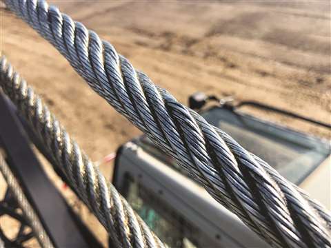
Your crane"s wire rope works hard. (Almost as hard as you do.) It can deteriorate more quickly than you might think, posing a real danger for you and your crew. In this article, we"ll answer the following questions.
Before we get into that, let"s take a brief moment to go over the proper wire terminology. Understanding the make-up of the wire rope allows you to have a clear understanding of when the rope needs to be replaced.
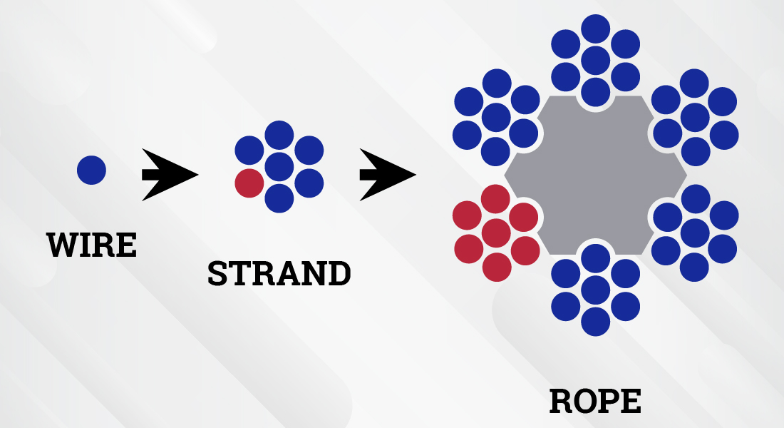
Flexible steel wire rope is made up of individual wires that make up a strand; these strands are then wrapped around a central core to make up a rope.
Understanding the difference between a wire and a strand is critical. If a strand (grouping of wires) in the rope breaks, the crane wire would need to be replaced. However, if a single wire in the strand breaks, the rope itself may still be usable.
Rag & Visual Inspections: In this method, you use a rag in your inspection, pulling it slowly across the strand, stopping for a closer and more detailed inspection wherever the rag gets caught on a wire.
The Diameter Measurement Method: This method involves comparing the diameter of your rope at various intervals with the rope"s official diameter per the manufacturer"s guidelines. A variation in the rope"s diameter can alert you to potential interior damage that a visual inspection would miss.
Localized Flaw Inspections (LF) vs. Loss of Metallic Area Inspections (LMA) - Both methods use electromagnetics to search for a wire rope"s internal damage.
According to OSHA"s safety regulations, you"re required to inspect your crane"s wire ropes at least every 12 months by qualified professionals. However, OSHA and other experts also recommend inspecting your wire ropes more frequently, such as after every initial installation or repair, or daily before each shift to ensure a safe work environment.
As discussed at the very beginning of this article, we can break down wire rope into three parts. First, wires, which make up strands, and then the strands wrapped around the central core make the rope. Of your total number of wires, you never want more than 10% to be damaged before you need to look into crane wire rope replacement.
According to OSHA, only "trained personnel should carry out inspections," and according to the Crane Manufacturers Association of America, a certified crane inspector should get 2,000+ hours of field experience and training.
We at Americrane & Hoist Corporation are just the experts you need, qualified to offer OSHA inspections and provide operator safety training classes to your employees. Contact us today!
Any electric wire rope is obviously a machine and so it is important to maintain and inspect them regularly and properly. Therefore, we understand when to change electric wire rope for good life span of a machine.
Every company should keep periodically wire rope maintenance of it. There are many statutory or regulatory agencies, which requirements should be fulfilled. In a case their requirements are not prevailing in your wire rope, you should inspect it properly. There are many electric wire rope hoists in India who manufactures good quality hoists and cranes.
It is essential for any employer to maintain their wire rope properly. Its working condition will decreases if it damaged, maltreated, overloaded or not truly maintained
It should be considered by a design factor for minimum or normal breaking strength if it reduced and it is not similar for all machines as well as work force so determine from design factor for your actual use strength.
A qualified person inspects a wire rope is properly installed or not and after proper inspection allows a rope for a regular service. If there would be any degradation in its strength, decision given by a good inspector to keep a rope in a service.
Rope measuring is an important factor for inspection process. Rope diameter is compared with original diameter and comes difference between them it shows that there is damage in a rope.
This website is using a security service to protect itself from online attacks. The action you just performed triggered the security solution. There are several actions that could trigger this block including submitting a certain word or phrase, a SQL command or malformed data.
Wire ropes undergo constant stress and wear through daily use. So, wire rope requires monthly inspection in accordance with this section to reduce the risk of failure and potential resulting injury or property damage. In addition, this section covers criteria to use in determining when to replace rope, and requires inspection of rope on equipment that has been idle for a month or more, before the rope and equipment can be returned to service.
A thorough inspection of all ropes shall be made at least once a month and a certification record which included the date of inspection, the signature of the person who performed the inspection and an identifier for the ropes which were inspected shall be kept on file where readily available to appointed personnel. Any deterioration, resulting in appreciable loss of original strength, shall be carefully observed and determination made as to whether further use of the rope would constitute a safety hazard. Some of the conditions that could result in an appreciable loss of strength are the following:
All rope which has been idle for a period of a month or more due to shutdown or storage of a crane on which it is installed shall be given a thorough inspection before it is used. This inspection shall be for all types of deterioration and shall be performed by an appointed person whose approval shall be required for further use of the rope. A certification record shall be available for inspection which includes the date of inspection, the signature of the person who performed the inspection and an identifier for the rope which was inspected.
Wear and damage to wire rope can’t always be seen on the surface. Konecranes RopeQ Magnetic Rope Inspection pairs visual inspection with non-destructive testing to detect internal broken wires that may escape detection through traditional inspection methods.
*The foregoing OSHA regulations are not intended to be a comprehensive overview of all applicable regulations pertaining to the designated topic. State laws may mandate different safety and maintenance standards. Accordingly, please consult applicable state laws as well as original equipment manufacturer specifications for further guidance. The statements and descriptions contained herein constitute the opinion/recommendation of the seller and are not intended to create any express warranties.

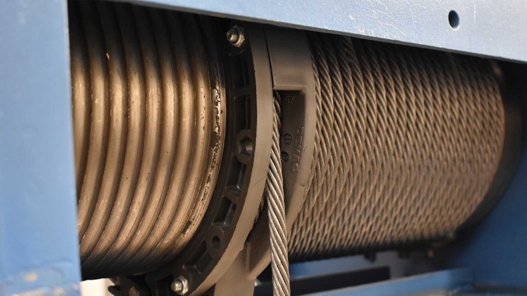
Wire rope is a machine! It is the workhorse that lifts the heavy loads on wire rope hoists. As a crane technician, there is an endless amount of information you should know about wire rope. The more you understand, the better resource you can be to your customers. Luckily, you don’t need to be the expert! There are others to help you out including, crane and hoist manufacturers, wire rope manufacturers, and other crane technicians. In this article, we will talk about how Demag designs wire rope hoists, selects the wire rope for models that you can buy today, and those you will still find in the field for inspections and repair.
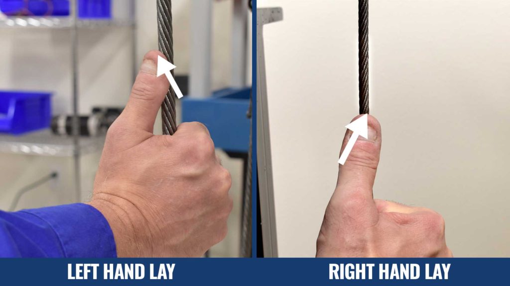
In the world of wire rope, lay has many meanings and definitions. First, we will go through the directional meanings. Lay can refer to the direction in which the strands are twisted around the core of the wire rope. When left hand and right hand lay is referred to like this, it is describing whether the strands are twisted clockwise (left hand) or counter-clockwise (right hand) around the core. For a frame of reference, grab the wire rope in either hand with your thumb pointing up. When the strand appears as if going up to the left, this is a Left Hand lay rope. When it appears as though it is going up to the right, this is a Right Hand lay.
Lay can also refer to the cut of the groove corkscrew in the drum and the corkscrew can go to the left or right. The wire rope will start gathering on the left-hand side of the drum in the case of a left lay and the opposite for right lay. One way to determine this is to look at the drum from the end where the rope is clamped. The term lay can be used to describe the distance of a complete wrap of a strand once around the core. When conducting a wire rope inspection, knowing how to measure the lay is critical. It is measured by determining the distance starting on the outside wrapping the strand one complete time back to the same outside position. This measurement is used to determine the maximum number of broken wires allowed within a single lay and for the number of broken wires in the same strand in a lay. Always consult your inspection criteria bodies, like CMAA and HMI, for the most up-to-date standards.
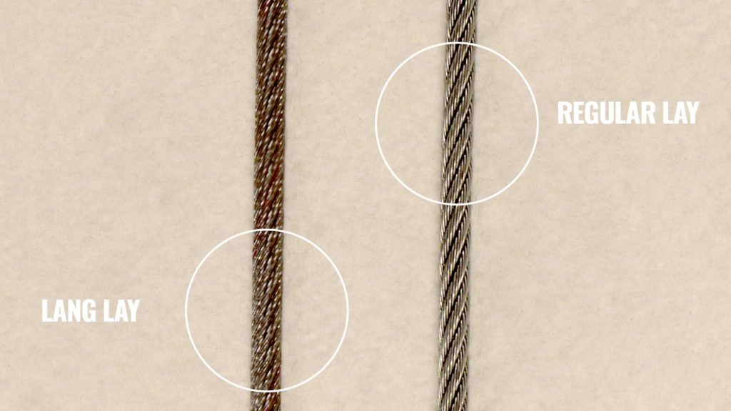
Lay can also denote whether a rope is Regular Lay or Lang Lay. Regular lay and Lang lay rope are different types of wire rope and differ based on the wire orientation in the strand. Regular lay rope wire appears as though the outermost wire surface is aligned parallel with the centerline of the wire rope axis. Lang lay rope wires appears to be at a 45 degree angle with the wire rope centerline axis. Lang lay type of rope allows for more surface contact with the groove surface on the drum or sheave, increasing the support zone and decreasing the load by spreading it out over a larger area. It is more costly to manufacture, but it can be used in special cases where better wear life for the drum and sheaves is needed. Today, Regular Lay rope is commonly used unless there is a specific design need to use Lang Lay wire rope.
Countries and industries may have different standards or best practices for wire rope. In the USA, the wire rope industry recommends using a Right Hand (RH) lay rope on a Left Hand (LH) drum corkscrew and a Left Hand (LH) lay rope on a Right Hand (RH) drum corkscrew. This is recommended for good spooling of the rope, especially on a grooveless drum. In most cases, Demag designs their wire rope hoists in violation of this best practice, but for a major engineering reason that benefits the user and for additional safety.
Demag wire rope hoists are designed for RH rope on a RH drum and LH rope on a LH drum. This design creates straighter drops of wire rope down to the bottom block as using the same strand lay and corkscrew twists the strands tighter around the core. The straighter drop eliminates interference in a 4/1 reeving configuration as the rope crisscrosses during lifting. This becomes very apparent when the lift height is around the 70 foot range. To make sure that the hoist has positive spooling, the drum is designed with a partial groove and is equipped with a rope guide with pressure rollers or a ring that keeps the rope in the groove.
When it comes to hoists configured for 4/2 reeving with 2 attachment points for the same rope, only one side of the drum follows the best practice. Since there are 2 attachment points in 4/2 reeving, one drum corkscrew is RH and the other LH. Inherent from the reeving design, close to vertical lifting is achieved and crisscrossing interference is not a concern.
Due to wear on the drum and sheaves, we will never recommend changing the lay of the rope used on a hoist when the wire rope needs changed. The existing wire rope lay has already established wear patterns on the drum and sheave that could make changing the rope with a different lay dangerous. Being able to identify or find out what type of rope is used on a wire rope hoist is key to success when wire rope needs changed.
Wire rope is a complex machine, lifting the heaviest loads like space shuttles and precast concrete components. It does the heavy lifting when a load is being lifted by a crane and wire rope hoist. Having a good understanding of wire rope is essential for all crane technicians. Being able to understand what lay means and how to determine what kind of rope is on an existing hoist is just the beginning. Not only will this knowledge allow you to be a more effective technician for your customers, but you can promote safety in the industry.

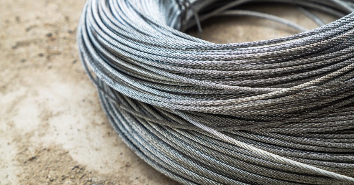
Wire rope slings have played a critical role in applications like lifting, rigging, and hoisting. They are usually made from galvanized or un-galvanized steel wire strands, which are woven into ropes with end terminations. The end terminations can be loops or hooks.
Several industries, such as mining, manufacturing, shipping, and power generation, use wire rope slings because they are easy-to-use, cost effective, and reliable. Depending on the type of load and crane, you can use an assembly of wire rope slings for lifting, rigging, and hoisting.
Although they are extremely strong and durable, wire rope slings require regular maintenance and inspection. They must be inspected to ensure safety and prevent economic losses. In this short guide, we will take a look at wire rope sling inspection, maintenance, and replacement.
As mentioned before, the purpose of wire rope sling inspection is to identify any damage or excessive wear before it leads to a disaster. Two leading organizations in the US, OSHA, and ASME have published inspection and maintenance guidelines to ensure wire rope slings safety and functionality.
The two standards governing the criteria and guidelines of wire rope sling inspection are OSHA 1910.184 and ASME B30.9. As per these guidelines, there are three types of inspections.
This inspection should be carried out immediately after receiving the wire rope slings. During this inspection, make sure to check the sling identification tags. These tags will bear the product information, its rated load capacity, and other specifications. Check if they are what you ordered and what you need.
The second type of wire rope sling inspection is to be carried out daily or prior to use. As wire rope slings are used in a wide range of applications, it is always better to inspect them before each use. In other words, if you are going to use a sling three times a day, you should inspect it three times.
As wire rope slings can get damaged during a loading or rigging application, this inspection is extremely critical. You can have designated personnel, usually a competent crew member, to inspect wire rope slings before each use.
Only a certified professional or service provider can carry out periodic inspections. You also need to document each periodic inspection and maintain records, as per the ASME B30.9 guidelines. The schedule of periodic wire rope sling inspection depends on factors like frequency of use, the severity of work conditions, type of lifting or rigging, and experience gained on the service life of wire rope slings used in similar applications.
Even though it’s usually a visual inspection, you have to be thorough with it. Neither OSHA nor ASME has specified any fixed sling inspection process. You need to set up a process of your own based on your requirements, rope sling usage, and other factors.
If possible, maintain a detailed record of all your sling inspections. Well-kept records make it easier to identify slings that are nearing the end of their service life or are damaged.
Sling tag identification is the most critical step in sling inspection. These tags help you identify the usage specifications of the slings. So, make sure to maintain the tags in excellent condition throughout the lifespan of the slings. If the tag is damaged or illegible, remove the sling from use immediately.
If you come across any of the following scenarios during your sling inspection, you will need to remove the slings immediately. Furthermore, if you are unsure of the potential damage, discontinue the use of slings.
As mentioned before, the tag bears all the vital information and specifications. If the tag is missing or illegible, it’ll be impossible to know the rated load capacity of the sling. If you end up using it for a load higher than the rated capacity, it can lead to an accident.
Wires: Wires are made from materials like steel, iron, bronze, and stainless steel. Wires surround the core, and they come in different sizes and strengths.
Distortion constitutes damages like kinking, crushing, and birdcaging, among others. If you see any such damage or wires and strands pushed out of their original positions, you need to replace the wire rope sling immediately.
Wire rope damage due to heat results in metallic discoloration, fusing of wires, or loss of lubricant. Make sure to replace the sling if there is heat damage.
If you see bent hooks with twisting exceeding 10 degrees or normal throat openings (measured at the narrowest point) exceeding 15%, you need to replace the sling.
While light surface rust will not affect the strength of wire rope slings, you will need a replacement if the corrosion has caused pitting or binding of wires.
When using wire rope slings, pulling through a loop can push out wires and strands from their original positions, pushing the slings out of balance. If you see this damage, replace the slings immediately.
Kinks are nothing but loops with permanent wire and strand distortions. As this type of damage is irreparable, you need to replace the slings right away.
Improper use of wire rope slings can cause doglegs, which are permanent bends. If the slings have minor doglegs with no strand distortion or if you can’t see them when the sling is under tension, you can continue using the sling. However, replacement is necessary if the doglegs are severe.
Make sure to discard the damaged wire rope slings in an eco-friendly manner. You should label the slings “Do Not Use” to avoid accidental use. Then, you should cut the eye and fittings from the rope, cut the rope into 3’ to 4’ sections, and send them for recycling.
The third most important step is wire rope sling maintenance. You should keep the following points in mind to ensure regular and comprehensive maintenance:
Wire rope slings play a critical role in a wide range of industries such as mining, manufacturing, and shipping, among others. Although they are strong and have a long lifespan, rope slings do need regular inspection and maintenance to ensure safety and longevity. Hopefully, this guide will help clear all your doubts regarding wire rope sling inspection, replacement, and maintenance. If you need help with any rigging equipment inspection, maintenance, and replacement, feel free to reach out to our team at Holloway Houston Inc.

This website is using a security service to protect itself from online attacks. The action you just performed triggered the security solution. There are several actions that could trigger this block including submitting a certain word or phrase, a SQL command or malformed data.
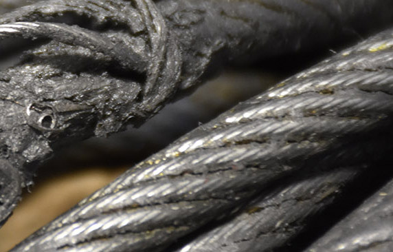
Use the "rag-and-visual" method to check for external damage. Grab the rope lightly and with a rag or cotton cloth, move the rag slowly along the wire. Broken wires will often "porcupine" (stick out) and these broken wires will snag on the rag. If the cloth catches, stop and visually assess the rope. It is also important to visually inspect the wire (without a rag). Some wire breaks will not porcupine.
Measure the rope diameter. Compare the rope diameter measurements with the original diameter. If the measurements are different, this change indicates external and/or internal rope damage.
Visually check for abrasions, corrosion, pitting, and lubrication inside rope. Insert a marlin spike beneath two strands and rotate to lift strands and open rope.
Corrosion from lack of lubrication and exposure to heat or moisture (e.g., wire rope shows signs of pitting). A fibre core rope will dry out and break at temperatures above 120°C (250°F).
Kinks from improper installation of new rope, sudden release of a load or knots made to shorten a rope. A kink cannot be removed without creating a weak section. Discarding kinked rope is best.
吊,搬送する大型天井クレーン等の分野で利用される。Description: TECHNICAL FIELD The present invention relates to a method for replacing a wire rope of a crane, and more particularly, to efficiently use an old wire rope wound around a hoisting drum installed on a crane. The present invention relates to a method of replacing a new wire rope with an old wire rope which can be automatically wound on the ground. This is used in the field of large overhead cranes that suspend and transport heavy objects such as coiled steel plates and ingots.
えたフックブロック8を懸吊している。A wire rope wound around a hoisting drum such as a large overhead crane installed in a rolling mill of a steel mill is, for example,
As shown in FIG. 10, both ends 6a, 6b thereof are hooked on fixtures 5a, 5b provided on the hoisting drum 5, and hooks 8a (the first hook) for hanging a load are attached via an upper sheave 7 which is a constant pulley. The hook block 8 provided with (see FIG. 9) is suspended.
いう)までも解く。In such an overhead crane, replacement work of the old wire rope 6 has been conventionally performed as follows. As shown in FIG. 9, first, the hoisting drum 5 is rotated in the hoisting direction (the direction opposite to the arrow 42), and the hoisting drum 5 is rotated.
The views of the old wire rope 6 are sequentially solved from the winding grooves 5c and 5d in the left-right inverted spiral shape engraved on the hook block 8, and the hook block 8 is lowered onto the support base 9 placed on the ground and firmly mounted.
Further, the hoisting drum 5 is rotated in the unwinding direction, and even the unwinding (also called discarding) left at the left and right ends of the winding groove is unwound.
Remove one end 6a (see FIG. 10) of the old wire rope 6 that is hung on the floor, tie the end 6a with a cremona rope (not shown), and lower it to the ground. Then, the Cremona rope is removed, and one end of the new wire rope 10 wound around the feeding means 11 arranged in advance on the ground and one end 6a of the old wire rope 6 are connected by a connecting fitting (not shown) or the like. . After that, the hoisting drum 5 is rotated in the hoisting direction 42, and the new wire rope 10 is started to be pulled up to the hoisting drum 5, while the old wire rope 6 is wound about three times around the winding groove 5d of the hoisting drum 5. Let This is to secure a frictional force such that the old wire rope 6 and the new wire rope 10 do not slip on the hoisting drum 5 when the hoisting drum 5 is subsequently rotated in the hoisting direction 42 and the old wire rope 6 is paid out. This is to keep it. After that, the other end 6b (the first end) of the old wire rope 6 hooked on the fixture 5b provided on the other end of the hoisting drum 5 (first
戻し、再度、上記と同じ作業を繰り返す。The other end of the old wire rope 6 is tied with a cremona rope or the like, and in this state, the hoisting drum 5 is further rotated in the hoisting direction 42, while the other end is guided so as not to bounce, while the club 4 is being guided. The old wire rope 6 is let out to the ground through the handrail 4a, and the worker waiting on the ground bundles the old wire rope 6 in a ring shape. During this operation, the old wire rope 6 wound around the winding drum 5 moves in the direction of the arrow 44 along the spiral winding groove 5d. When the wound portion of the old wire rope 6 reaches the central position approaching the winding groove 5c of the reverse spiral, there is no winding allowance for the old wire rope 6 to move, and at that time, the rotation of the hoisting drum 5 To stop. The old wire rope 6 in the wound state is loosened on the hoisting drum 5 by the operator"s manual work so as to float from the winding groove 5d, and the old wire rope 6 is left as it is at the left end of the winding groove 5d where the fixture 5b is located. Return to and repeat the same operation as above.
了される。When the connection between the new wire rope 10 and the old wire rope 6 reaches the upper position 43 of the hoist drum 5 by sequentially tracing the hook block 8 and the upper sheave 7 (see FIG. 10) by such work. The rotation of the hoisting drum 5 is stopped, the connecting portion is disconnected, and one end of the new wire rope 10 is hooked on the fixture 5b of the hoisting drum 5. The other end 6b of the old wire rope 6
Is tied with a cremona rope, and it is lowered to the ground, and the last part of the old wire rope 6 is also bundled into a ring on the ground. On the other hand, the other end of the new wire rope 10 is removed from the feeding means 11, the other end is tied with a cremona rope or the like and pulled up onto the club 4, and the other end is hooked on the fixture 5a of the hoisting drum 5. After the hoisting drum 5 is rotated in the hoisting direction 42 and the new wire rope 10 is additionally wound at both ends of the hoisting drum 5, the hoisting drum 5 is further rotated in the hoisting direction, whereby the new wire rope 10 Is wound around the hoisting drum 5, and the hook block 8 rises. In this way, the replacement work of the old wire rope 6 and the new wire rope 10 is completed.
非常に煩わしいものであった。In such a conventional replacement method, while rotating the hoisting drum 5 at the high position of the ceiling part, the old wire rope 6 is unwound to the ground, while the unwound old wire rope 6 is bundled by the operator on the ground. It was being done. For large overhead cranes, the diameter of the wire rope used for them is as large as 25 mm to 40 mm, and the work of bundling them is not very efficient because it requires a lot of manpower and is a very heavy work. In addition, it is necessary for the bundling operator and the crane operator to work while constantly signaling each other.
提案した。For this reason, the applicant of the present invention, after fixing the hook block to the ground, connects one end of the old wire rope to the new wire rope and connects the other end of the old wire rope to the winding means separately prepared. JP-A-63-17792 proposes a method for replacing the wire rope of a crane, in which the old wire rope is wound up only by the pulling force driven by the winding means without driving the hoisting drum. did.
善が強く望まれていた。In the above method, the pulling force of the winding means arranged on the ground acts on the entire wire rope, and by extension, the old wire rope in the portion stretched between the upper sheave and the hook block is also directly affected. It was necessary to fix the hook block particularly firmly. In addition, the strength of the winding means must be increased in order to obtain a sufficient tensile force, and the drive source requires considerably large power. This is even more so when the wire rope is thick and heavy, which causes problems such as an increase in the size of the device and an increase in cost, and a restriction on the work space. Further, since a large tension acts on the wire rope, the connection portion between the new wire rope and the old wire rope may be disconnected, and improvement of the work has been strongly desired.
ープ取替方法を提供することである。The present invention has been made in consideration of such circumstances, and an object of the present invention is not to require a compact and large space, to keep a large tension applied to the wire rope at all times, and to make the wire rope thick. It is an object of the present invention to provide a method for replacing a wire rope of a crane, in which the safety of the replacement work is highly secured and the wire rope can be efficiently replaced with a new wire rope.
けるワイヤロープの取替方法に適用される。INDUSTRIAL APPLICABILITY The present invention is applied to a method for replacing a wire rope in a crane equipped with a hoisting drum for winding a wire rope, which is installed on a truck traveling on a rail.
It is lowered to the ground by rotating in the winding direction (the direction opposite to the arrow 42), and is unwound from the hoisting drum 5 to the old winding of the old wire rope 6. The one end 6a of the old wire rope 6 is removed from one end of the hoisting drum 5, and the one end 6a of the old wire rope 6 is lowered to the ground and connected to one end of the new wire rope 10 wound around the feeding means 11. Next, the hoisting drum 5 is rotated in the hoisting direction 42, and the old wire rope 6 is wound around the hoisting drum 5 a predetermined number of times. Remove the other end 6b. Rotate the hoisting drum 5 further in the hoisting direction 42,
The new wire rope 10 is started to be pulled up to the hoisting drum 5, and the other end 6b of the old wire rope 6 is fed to the ground. The other end 6b of the old wire rope 6 is connected to the rotary table 17 arranged on the ground, and the winding direction of the winding drum 5 thereafter is increased.
The old wire rope 6 is fed to the ground by rotating the old wire rope 6 and the rotation speed of the rotary table 17 is adjusted so that the old wire rope 6 has a desired winding diameter without tension. That is, the ropes 6 are stacked in a ring shape and bundled.
うにしてもよい。Further, referring to FIG. 5, the iron cage 18 having a cylindrical iron cage 18a surrounded by the old wire ropes 6 which are stacked in a ring shape is detachably provided on the rotary table 17 and is fed to the ground. The old wire rope 6 may be bundled in a ring shape by the rotation of the rotary table 17 while preventing the winding wire of the old wire rope 6 from being disturbed by the cylindrical basket portion 18a.
輪状に重ね束ねるようにしてもよい。Then, a truncated cone small cross basket 18c is formed in the upper part of the truncated cone shaped cross basket 18b, and the truncated cone small cross basket 1 is formed.
While contacting the old wire rope 6 that has been fed to the ground through the upper opening of 8c, to the ring-shaped pipe material that is located at the boundary between the truncated cone-shaped groin portion 18b and the truncated cone-shaped small groin portion 18c. Alternatively, the old wire ropes 6 may be stacked and bundled in a ring shape by the rotation of the rotary table 17.
とした巻き取りを実現することができる。According to the present invention, one end of an old wire rope removed from a hoisting drum is connected to a new wire rope, and the old wire rope is wound around the hoisting drum a predetermined number of times, and then the hoisting drum is rotated in a hoisting direction. Since the other end of the old wire rope is drawn to the ground while being made to move, the old wire rope can be reliably drawn without slipping, and the new wire rope can be wound around the hoisting drum. Then, the old wire rope is extended to the other side by the rotation of the hoisting drum in the winding direction and the rotation speed of the rotary table is adjusted to connect the old wire rope to the movement of the rotary table arranged on the ground. Since the wire rope is wound, it is possible to efficiently stack the old wire ropes in a loop so that the old wire ropes have a desired winding diameter without exerting a large tension on the wire ropes. That is, if the rotation speed of the rotary table is increased, the winding can be made thinner, and if the winding is tightened too much, it can be slowed down and corrected, or a large bunch of wheels can be stacked. Orderly winding can be achieved with any diameter.
ないものとしておくことができる。If a carcass with a cylindrical cage that surrounds the old wire ropes that are bundled in a ring shape is detachably attached to the rotating table, the disorder of the winding appearance of the old wire ropes that have been fed to the ground will be cylindrical. Part is prevented by
The old wire rope can be smoothly looped and bundled by rotating the rotary table. For example, if the old wire rope suddenly jumps out, the cylindrical cage prevents it. Further, even if the ring-shaped bundle is greatly tilted, it is prevented from deviating from the turntable. Of course, the old wire ropes can be bundled compactly to facilitate the subsequent treatment, and the winding means can be made to require no space.
しておきたい場合に都合がよい。By forming a truncated cone-shaped basket on the upper part of the cylindrical basket, the old wire rope that is fed to the ground is brought into contact with the inner surface of the truncated cone and the rotary table rotates to form a ring shape. Can be stacked and bundled. For example, even if a situation occurs in which the old wire rope is excessively shaken by centrifugal force or the like due to the rotation of the turntable, the wound form after that is not greatly impaired. This is convenient when it is desired to keep the winding diameter large.
同心状の巻取り姿となるよう誘導することができる。A small frustoconical small squirrel cage is formed in the upper part of the frustoconical squirrel cage, and the old wire rope that is fed to the ground through the upper opening of the frustoconical small squirrel cage is cut into a truncated cone shape. The old wire ropes can be looped and bundled by rotating the rotary table by contacting them in a ring-shaped pipe shape located at the boundary between the pallet cage and the truncated cone small pallet cage. Not only does the frustoconical small squirrel cage guide the movement of the old wire rope to suppress unnecessary fluctuations, but the frustoconical small squirrel cage is narrower toward the top to allow the old wire rope to be thin. It is possible to prevent the body from jumping out of the body and guide it to have a concentric winding shape.
等の重量物を懸吊,搬送するものである。The wire rope replacement method shown in the present embodiment efficiently uses a thick and rigid old wire rope wound around the hoisting drum of a crane by using a vertically-shaped winding means that is compactly formed. It is a new wire rope that can be replaced and the old wire rope can be wound and bundled without requiring a large amount of power. The crane to which this wire rope replacement method is applied is, for example, a large overhead crane 1 as shown in FIG.
ーブ7を介してフックブロック8を懸吊している。As shown in FIG. 1, rails 3a, 3a are laid on a girder 3 of the overhead crane 1, and a club 4 as a truck moving on the rails 3a is rotated by a drive source (not shown). The hoisting drum 5 is stationary. The winding drum 5 is provided with spiral winding grooves 5c, 5d in the opposite direction on the left and right, and both ends 6a of the old wire rope 6 wound along the winding grooves 5c, 5d. As shown in FIG. 10, the wires 6b are hooked at both ends of the hoisting drum 5, and the wire ropes 6 thereof are hooked via the upper sheave 7 arranged at the lower part of the hoisting drum 5. Is suspended.
ブブロック(図示省略)に軸支されている。The hook block 8 pivotally supports four movable pulleys 8A, 8A, and a load hanging hook 8a (see FIG. 1) is hung at the bottom thereof. That is, the fixtures 5a and 5b for attaching the wire rope are provided at both ends of the hoisting drum 5, and the wire rope in which the hook block 8 is suspended via the upper sheave 7 on the fixtures 5a and 5b. One end 6a and the other end 6b of 6,
They are wound and hooked in the same direction. The upper sheave 7 is composed of, for example, three constant pulleys 7A, and is pivotally supported by a sheave block (not shown) suspended below the club 4 at a position immediately below the hoisting drum 5.
を巻き取る巻取手段12とにより構成される。As shown in FIG. 1, the wire rope replacement device has a support base 9 placed on the ground for mounting the hook block 8 and one end 6a of the old wire rope 6 removed from the hoisting drum 5. A feeding means for feeding the new wire rope 10 to be connected
9上でも充分な安定を得ることができる。The support base 9 is a base with four legs having a mounting surface on the top, and is simple enough for an operator to easily carry. As will be described later, since the old wire rope 6 to be replaced is unwound by the hoisting drum 5, a large external force does not act on the hook block 8 via the old wire rope 6 during the replacement work. It is possible to obtain sufficient stability even on a simple support base 9.
を、順次繰り出すことができるようになっている。The feeding means 11 has a rotatable disc (not shown) inside an annular base 14 having a plurality of shelves 13 arranged on the outer periphery thereof, and a core member protruding in the center of the disc. A new wire rope 10 is coiled around and mounted on a disk around 15
と共に駆動源19により回転されるようになっている。The winding means 12 is, as shown in FIGS. 4 and 5, a vertical guide shaft 16 for guiding the old wire rope 6 unwound from the winding drum 5 to be wound up.
In order to enclose the horizontal rotary table 17 that rotates with the guide shaft 16 to receive the old wire rope 6 in a ring shape, and the old wire rope 6 that is detachably provided on the rotary table 17 and is bundled in a ring shape. And a vertical frame 18 to be arranged, and the rotary table 17 is provided with a guide shaft 16
ている。The rotary table 17 is formed in a disk shape and is integrally assembled with a cylindrical guide shaft 16, and a pivot shaft 20 extending downward from the guide shaft 16 is pivotally supported by a bearing 22 fixed to a mount 21. In addition, the turntable 17 is mounted on four rotatable rollers 23, 23 that are radially supported on a pedestal 21.
けている。The iron cage 18 is a ring-shaped pipe material 24 arranged laterally so as to surround the outer circumference of the old wire rope to be wound up.
Is provided with a cylindrical cross-shaped cage 18a, which is a combination of the pipe members 25 arranged in the vertical direction so as to intersect with each other, and on the upper part thereof, a two-pointed truncated conical cross-shaped cage for introducing and guiding an old wire rope. The portion 18b is provided with a truncated cone small cross-section basket 18c.
By fitting the lower part of 5 into the pile material 26 as a receiving member which is erected on the peripheral portion of the rotary table 17, the cross cage 18 is detachably assembled to the rotary table 17 as shown in the figure.
The vertical geared motor of the inverter control system as 19 is erected. A sprocket 27 is fixed to the output shaft projecting downward, and a sprocket 29 fixed to the lower end of the pivot shaft 20 integrated with the guide shaft 16 via a chain 28.
けられている。By the driving force of the vertical geared motor 19 described above, the guide shaft 16 integrated with the rotary table 17 and the cross cage 18 are rotated, and the old wire rope introduced from the upper opening of the truncated cone small cross cage 18c. 6 (see FIG. 1) can be bundled around the guide shaft 16 in a ring shape. The angle members 30 are radially arranged on the rotary table 17 so that a small space is formed under the bundled old wire ropes so that the bundled old wire ropes can be easily taken out. Also,
Manual screw-type jacks 32 are provided at four positions so that the winding means 12 can be moved easily so that the winding means 12 can be easily aligned before starting the winding operation and can be stably positioned and fixed.
Has only to have an output enough to stack and bundle the fed old wire ropes 6, and the output is relatively small such as 3.7 kw. Cross cage 18 and rotary table
The drive source 19 is not necessary because 17 can be easily rotated directly by input, but it is preferable to install a vertical geared motor, and the frequency as shown in FIG. By the operation box 33 with a meter, it is possible to perform forward / reverse and variable speed operation.
ッチ、第7図中の41は目盛校正抵抗である。The operation box 33 with a frequency meter is small enough to be carried and remotely operated by an operator (see FIG. 1) and has an internal circuit as shown in FIG. 7, and for example as shown in FIG. External connections are made. In FIG. 6, 34 is an input display neon lamp, 35 is a frequency display panel, 36 is a lower limit frequency adjusting screw, 37 is an upper limit frequency adjusting screw, 38 is a frequency setting knob, 39 is a reverse rotation start signal switch, and 40 is A forward rotation start signal switch, 41 in FIG. 7 is a scale calibration resistor.
The rotation speed of the rotary table 17 can be adjusted according to the descending speed of the old wire rope 6 fed out from the table, so that the old wire rope 6 can be bundled without wasting space, and the old wire rope 6 can be bundled by changing the rotation speed. The ring diameter can be changed arbitrarily each time. Further, the operator can carry the operation box 33 with the frequency meter and operate it in any safe place.
に説明する。The replacement work of the old wire rope 6 and the new wire rope 10 by the wire rope replacement device thus configured will be described below.
置した支持台9上にフックブロック8を載置する。(A) First, as shown in FIG. 1, the old wire rope 6 is unwound by rotating the hoisting drum 5 in the lowering direction (the direction opposite to the arrow 42), and the hook block 8
And the hook block 8 is placed on the bottom surface, that is, on the support base 9 arranged at the lowest portion when a pit or the like is formed on the ground.
端に、連結金具(図示せず)等で接続する。(C) The one end 6a of the old wire rope 6 is removed from the fixture 5a of the hoisting drum 5, and the one end 6a is tied with a cremona rope (not shown) or the like and manually lowered to the ground. And after removing the cremona rope, one end 6a
るためである。(D) Next, as shown in FIG. 2, the hoisting drum 5 is rotated in the hoisting direction 42, and the old wire rope 6 is wound around the winding groove 5d of the hoisting drum 5 a predetermined number of times, for example, about three times. After that, the other end 6b of the old wire rope 6 hooked on the fixture 5b of the hoisting drum 5 is removed. In addition, when the hoisting drum 5 is rotated, the above-described three times of winding do not cause the old wire rope 6 wound around the hoisting drum 5 to slip from the hoisting drum 5 and prevent the old wire rope 6 from winding. This is so that a desired frictional force can be exerted at the time of feeding and raising the new wire rope 10.
の下部に連繋,固定する。(E) The hoisting drum 5 is further rotated in the hoisting direction 42, and the new wire rope 10 is started to be pulled up to the hoisting drum 5, and the other end 6b of the old wire rope 6 is tied with the cremona rope. The handrail 4a of the club 4 shown in FIG. 1 is guided by a Cremona rope so that the end 6b does not bounce.
も、回転テーブル17から逸脱することが防止される。(F) If the winding means 12 is rotated by the drive source 19 while rotating the hoisting drum 5 in the hoisting direction 42, the old wire rope 6 is fed toward the ground by the rotational force of the hoisting drum 5. In this state, the old wire rope 6 can be wound inside the cage 18 by unwinding the old wire rope 6 to the ground and adjusting the rotation speed of the rotary table 17. That is, if the rotation is accelerated by the speed control of the rotary table 17, the winding can be thinned, and if the winding is tightened too much, the winding can be slowed to correct or a large ring is piled up. Orderly winding is realized. In this winding operation, the new wire rope 10 is unwound from the unwinding means 11 as much as the old wire rope 6 is wound up. As shown in the figure, if the guide shaft 16 is erected at the center of the rotary table 17, the winding state of the old wire rope 6 can be maintained at the center. Although the iron cage 18 may be omitted, if it is provided, the winding appearance of the old wire rope can be prevented from being disturbed. That is, even if the old wire rope 6 suddenly jumps out, the pipe material 25 of the cylindrical basket 18a blocks it.
溝5dに沿って固定具5b側へ逆戻りされる。(G) A winding groove in which the old wire rope 6 wound around the winding drum 5 is spirally engraved in the middle of this work.
The winding drum 5 is moved along the direction 5d in the direction of the arrow 44 to reach the end of the winding groove 5d at the substantially central position, so that the winding drum 5 is stopped from rotating. When the wire rope is thin and slightly light, the old wire rope 6 is loosened on the hoisting drum 5 by the operator"s manual work and floated from the winding groove 5d.
Return to the left end where the fixture 5b is located. If the wire rope is thick and heavy, the operator should remove part of the old wire rope 6 from the handrail 4a.
Loosen a little above. When the hoist drum 5 is further rotated in the same direction in a state where the old wire rope 6 is floated to the extent of causing slippage with the winding groove 5d, the old wire rope 6 is fixed along the winding groove 5d with the fixture 5b. It is returned to the side.
ねられる。(H) While repeating the above procedure, the operation of feeding the old wire rope 6 to the ground is performed by rotating the hoisting drum 5 in the winding direction, but the old wire rope 6 is not subjected to a strong tension, The old wire ropes 6 are looped and bundled on the turntable 17 so that the desired winding diameter is obtained.
Disconnect the connection. One end 6a of the old wire rope 6 is bound with a Cremona rope or the like, while one end of the new wire rope 10 is attached to the fixture 5b. One end 6a of the old wire rope 6 is gradually lowered to the ground by a worker on the club 4 using a cremona rope. At that time as well, the winding means 12 is rotated, and when all the old wire ropes 6 are bundled, the work of collecting the old wire ropes 6 is completed.
ックブロック8も上昇する。(J) Remove the fixed end of the new wire rope 10 from the feeding means 11, tie it with a cremona rope, and pull it all up on the club 4, and hook the other end on the fixture 5a of the hoisting drum 5. Rotate the hoisting drum 5 further and use the new wire rope 10
When the winding wire is wound around both ends of the hoisting drum 5 and further wound up, the new wire rope 10 is wound around the hoisting drum 5, and the hook block 8 also rises.
とは言うまでもない。In the winding operation performed in this manner, since the old wire rope 6 is unwound by the rotational force of the hoisting drum 5, a large tension based on the drive of the winding means 12 acts on the old wire rope 6 as in the conventional case. There is nothing to do. Therefore, disconnection of the connection between the old wire rope 6 and the new wire rope 10 is avoided. Further, since the force via the old wire rope 6 does not act on the hook block 8 as in the conventional case, the support base 9 can be relatively small, and the hook on the ground is not required. The block 8 can be easily supported. By the way, a cage
It goes without saying that if the 18 is removed from the rotary table 17, the wound old wire rope 6 can be easily taken out from the winding means 12.
生じても以後の巻取り姿を大きく損なうことはない。By the way, if the casket body 18 is provided with the truncated cone-shaped cage part 18b in the upper portion as shown in FIG. 5, the old wire rope 6 fed to the ground is brought into contact with the inner surface of the truncated cone-shaped casket part 18b. On the other hand, the rotary table 17 can be rotated and stacked in a ring shape. This is convenient when the winding diameter is often increased, as indicated by the dashed line. For example, even if a situation occurs in which the centrifugal force based on the rotation of the rotary table 17 acts excessively on the old wire rope 6 to cause it to be swung, it does not significantly impair the subsequent winding state.
滑な誘導が実現される。Further, when the truncated cone small cross basket 18c connected to the upper part of the truncated cone cross basket 18b is formed, the old wire which is fed to the ground through the upper opening of the truncated cone small cross basket 18c. While the rope 6 is in contact with the ring-shaped pipe material 24A located at the boundary between the frustoconical spatula portion 18b and the frustoconical spatula portion 18c, the old wire ropes 6 are bundled in a ring shape by the rotation of the rotary table 17. be able to. In this case, as shown by the chain double-dashed line, the inner ring surface of the pipe member 24A guides the movement of the old wire rope 6 and suppresses unnecessary wobbling of the old wire rope 6. Of course, the frustoconical small squirrel cage 18c becomes narrower as it goes upward, so that when the old wire rope is thin, it is prevented from jumping out of the squirrel cage 18 and a smooth concentric guidance is realized.
とすることができる。The winding means 12 does not require a particularly strong winding force as in the conventional case, and a rotating force for binding the old wire rope 6 fed out over the handrail 4a of the club 4 at its lower position to the rotary table 17. Just give it. Therefore, the vertical geared motor 19 serving as a drive source thereof can have a low output. Further, since the winding means 12 is hardly affected by the tension of the old wire rope 6, it is not necessary to fix it to the ground. Because of this, the old wire rope 6 can be made small together with the adoption of the cross cage 18, and the winding means 12 can be made more compact than the conventional one.
プ6の巻取り姿の減容化が図られる。This winding means 12 is usually arranged directly below the club 4, but by employing the operation box 33 with a frequency meter, the worker can select a safe place as appropriate and position it. High safety is ensured. Needless to say, the adoption of such a winding means 12 relieves the operator from the winding work that requires heavy muscle strength. In addition, operate the frequency setting knob 38 of the operation box 33 with frequency meter to turn the rotary table.
Even if the diameter of the old wire rope 6 is as thick as 40 mm and has high rigidity, the winding diameter in the carcass 18 can be reduced or increased, and the winding shape of the old wire rope 6 can be increased. The volume can be reduced.
パイプ材、42……巻き上げ方向。FIG. 1 is an overall configuration diagram of a wire rope replacement device used for carrying out the method of the present invention, FIG. 2 is a schematic diagram showing a tensioned state of the wire rope during replacement work, and FIG. FIG. 4 is a perspective view of the crane, FIG. 4 is a plan view of the winding means, and FIG.
6 is a perspective view of the operation box with a frequency meter, FIG. 7 is its internal circuit diagram, FIG. 8 is its external connection diagram, and FIG. 9 is a conventional wire rope. Replacement work diagram, No. 10
The figure is a schematic view showing a state in which the wire rope is stretched in a normal state of the crane. 1 ... Crane (overhead crane), 3a ... Rail, 4 ...
… Club (carriage), 5 …… Winding drum, 6 …… Old wire rope, 6a …… One end, 6b …… Other end, 8 …… Hook block, 10 …… New wire rope, 11 …… Feeding means, 17-Rotary table, 18-Case cage, 18a-Cylindrical cage section, 18b
───────────────────────────────────────────────────── フロントページの続き (56)参考文献 特開 昭63−17792(JP,A) 実開 昭60−72450(JP,U) 特公 昭53−30226(JP,B2) ─────────────────────────────────────────────────── ─── Continuation of the front page (56) Reference JP-A-63-17792 (JP, A) Actual development Shou 60-72450 (JP, U) JP-B 53-30226 (JP, B2)

Due to aggressive automated scraping of FederalRegister.gov and eCFR.gov, programmatic access to these sites is limited to access to our extensive developer APIs.
If you are human user receiving this message, we can add your IP address to a set of IPs that can access FederalRegister.gov & eCFR.gov; complete the CAPTCHA (bot test) below and click "Request Access". This should only be necessary once for each IP address you access the site from.
If you want to request a wider IP range, first request access for your current IP, and then use the "Site Feedback" button found in the lower left-hand side to make the request.

As a result of the heavy responsibilities placed on wire rope, it is no wonder why a cable suffers from wear and tear. The most common problem that occurs when using wire rope, is block twisting or cabling. This is especially the case for companies using wire rope within the construction industry. When this happens, it is easy to blame the rope, but normally there are other issues that need to be addressed.
Each time a load is applied to a wire rope, it will slightly twist or unlay. With time, the wire rope will eventually suffer from block twisting or rope distortion. When the problem gets too big (roughly 180 degrees of twisting), it is best to no longer use the rope. Using a rope that has been cabled is dangerous and unsafe for workers.
Since 1981 All-Lift Systems has been the leader of manufactured Wire Rope products. Our Wire Rope Departments are the largest in the State of Wisconsin & Michigan’s U.P.. We hold the largest inventory of domestic, specialty, and foreign wire ropes such as Aircraft Cable, GAC, Cable Strand, Stainless Steel, IWRC, EIP, Fiber Core, Anti-Rotation, Python Family Of Ropes, Cushion Pac, and even more. All-Lift Systems purchasing volume allows us to buy at low cost from suppliers like Southern, Indusco, Python, Samson and more. We serve the agricultural, construction, marine, forestry, industrial, municipal, and recovery industries. Our staff can provide design & engineering for your lifting needs, qualified Wire & Synthetic Rope Technicians are able to produce mechanical & hand splice wire & synthetic rope chokers (including eye, grommet, and butt splices), thimble eye, two, three, and four legged bridles, along with wire rope grommets, endless, and roller wire rope slings. We also stock all fittings and hardware to create winch lines, hoist lines, buttons, and logging chokers. Need a custom wire rope assembly that may be very small diameter / length or a custom cable holding or lifting assembly, we can handle large volume orders, can mass produce, and meet your shipping requirements. Do you need inspection of 5, 100, 1000, 5000, or 20,000 plus feet of wire or synthetic rope. Please visit our walk in and on line stores, or call one of our knowledgeable and dedicated customer service specialists we are eager to earn your business!
The more wires there are in a strand of wire rope of a given diameter, the more flexible that rope will be. One of the key aspects of the usefulness of rope, wire or otherwise, is its ability to bend and wrap around pulleys and sheaves. If a rope cannot bend, it will not be as useful.
When a rope does bend, the wires and strands that make up the rope slide on top of each other. Because of this, wire ropes that will experience significant bending will need to be lubricated. In addition, the actual wires experience bending stress which can, over time, lead to fatigue failure. If the stresses are higher than the yield point of the wires, the wire rope may experience a permanent deformation.
Each strand in a wire rope is comprised of multiple wires (usually 7, 19, or 37). A rope with 7 strands of 19 wires would be referred to as a 7×19 wire rope. This type of designation serves as the class of the wire. These numbers may be followed by a pair of letters that provide information about how the outside layer of the wire rope is constructed.
The lay of a rope refers to how the wire strands are twisted. A regular lay wire rope has the wires twisted one way and the strands twisted in the opposite direction. A lang lay, on the other hand, has the wires and strands wrapped in the same direction. A regular lay is going to be less likely to kink or untwist compared to a lang lay, but a lang lay is going to have better abrasion resistance and flexibility. Lay can also be designated as right or left: a right lay wraps around the core in a clockwise direction, while a left lay wraps around in a counter-clockwise direction.
The finish of a wire rope refers to the coating (if any) applied to the strands. If a rope is described as bright finish, it is made from high carbon steel wires that have no finish or protective coating applied to them. A galvanized finish has a coating of zinc added to enhance corrosion protection. Another finish option is a zinc aluminum coating added to wire for 3x better corrosion protection than a galvanized finish.
The more wires there are in a strand of wire rope of a given diameter, the more flexible that rope will be. One of the key aspects of the usefulness of rope, wire or otherwise, is its ability to bend and wrap around pulleys and sheaves. If a rope cannot bend, it will not be as useful.
When a rope does bend, the wires and strands that make up the rope slide on top of each other. Because of this, wire ropes that will experience significant bending will need to be lubricated. In addition, the actual wires experience bending stress which can, over time, lead to fatigue failure. If the stresses are higher than the yield point of the wires, the wire rope may experience a permanent deformation.
There are several key wire rope characteristics that must be considered when choosing the right one for your application. One of the most important characteristics of wire rope is its strength which is typically reported as its minimum breaking force (MBF). However–and this is very important–a wire rope should never be used at its MBF.
A stranded rope should also have an application-appropriate crushing resistance. The crushing resistance refers to the rope’s ability to resist having its cross-section, stands, wires, or core deformed by outside forces. This is similar to the ability of a rope to resist deformation in the form of wire rope peening, where the outside wires of the rope appear to have been hammered.
Fatigue resistance is another key aspect of choosing the right wire rope and particularly applies to ropes that experience bending stresses. The longer a wire rope is exposed to bending stresses, the less strength it is going to have. A rope with a higher fatigue resistance is going to have a longer useful life. The more wires in a rope, the better its fatigue resistance. However, the size of the wire rope also plays a key part: ropes should not be bent over drums or sheaves that force the rope to bend sharply.
When a load is placed on a rope, the wires will try to straighten out to accommodate a load, generating a torque that can cause the rope to spin. Some need to be rotation resistant wire rope to prevent the load from rotating when applied to the rope. A similar characteristic is the stability of the rope, which refers to the ability of the rope to spool smoothly or avoid tangling.
Another key wire rope characteristic is its resistance to metal loss, which usually affects the outside wires of the rope and occurs through abrasion. As the rope rubs against other hard surfaces, metal can be worn away from the outer wires.
Overhead crane wire ropes are used in many different industries, including mining, oil & gas, marine, steel, logging, ski lifts, and elevators. It is vitally important that you find the right wire rope for your application, whether you need a rotation-resistant wire rope for a critical petrochemical application or a general-purpose wire rope for a winch. If you are in the market for stranded core wire rope, contact the experts at Hi-Speed Industrial Service.

When most folks think of Texas, they think big – big hats, big guns, big hair. But if you travel about as far south as a car will take you, just one long bridge away from the excitement of South Padre Island, you’ll eventually reach Port Isabel, a small town situated just off the western edge of the Gulf of Mexico.
With a population of about 5,000, the town is small, but it’s also somewhat lively, and it’s not uncommon to see crane booms stretching into the sky above the cerulean waters of the Gulf. The economy isn’t necessarily booming by any means – most of it is built on tourism that is spotty at best – but construction jobs are still underway and cranes can be found picking and setting everything from rebar to HVAC units to generators.
But on one particular day in early May of 2009, it wasn’t a boom reaching toward the big Texas sky that was causing people to stop and stare; it was one that was lying in a heap just beside the water, lattice sections bent and lacings twisted into mess of mangled steel and frayed wire rope. “I got the call to investigate the cause of loss on a Manitowoc 888 that was being used to drive underwater pilings at a dock in Port Isabel,” says JR Bristow, of Bristow Truck and Equipment Specialists, an organization based in Ridgewood, NJ that provides failure analysis and appraisals, among other things, for heavy equipment. “The operator was hoisting th


 8613371530291