
wire rope break test made in china

We work as a team and treat each other with respect. Our solid, capable and knowledgeable team is valued as the greatest asset and an integral part of the business.
Beijing Tianma Sling Co., Ltd has been in heavy lifting industry for more than 15 years. We are specialized in manufacturing all sizes of webbing slings, round sling, lashing straps, towing straps, polyester webbing, wire rope press machine, hydraulic testing machines, wire rope sling and other rigging equipment to the world market.

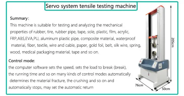
WAW – 1000D Hydraulic Universal Testing Machine,the load frame appearance is streamline designed and exquisitely made, four poles and double guide screws form loading test space; Underneath oil cylinder use hydrostatic oil film clearance seal technology, Upward-Downward moving beam adopt turbine, worm transmit mechanism and eliminate gap mechanism, it make sure the beam moving smoothly. without gap, collect part is semi-open type, using imported high accuracy load sensor measuring test force directly, with high accuracy indicating value: ±1% and wide measuring range: 2-100%. Oil source system adopt integrate control cabinet, with integrated servo, clamp oil source. Use imported high pressure gear pump, steady and no impacting, new independent control system is reliable and steady, also has high sampling frequency.

Elevator Rope Attachment, Rope socket,Rope thimble, Wire Rope Wedge Socket, Rope Fastening Socket, Lift Roping Fastener, Elevator Wire Rope Socket, Lead poured type Wire Rope Socket Rope Fastening Socket, Lift Wire Rope Thimble, Elevator Components Nova has been making and supplying Wedged type and Lead poured type Elevator Rope Attachment which is suitable for various wire rope in big volume every year as to customers’ requirements. 1.Wedged type NV26-Q001(Φ8~Φ13) NV26-Q 002A(Φ16~Φ20) NV26-Q0 02B NV26-Q 003A( Φ8~Φ16,Socket head casted ) NV26-Q 003B(Φ8~Φ16,Socket head forged ) NV26-Q 003C( Φ8~Φ16,Socket head forged ) 2.Lead poured type NV26-G001(Φ8~Φ16) NV26-G002(Φ8~Φ20) Re: 1. All Rope attachment meets standard DIN15315 and DIN43148. 2. Rope attachment parts can be made as casting and forged ones. 3. Passed the testing of the National Elevator Inspection and Testing Center and also being applied by many overseas elevator Nova welcomes you to visit our website for its more technical specifications or email us to get our elevator Rope attachment preliminary inquiry sheet for your selection.

Wire rope and cable are each considered a “machine”. The configuration and method of manufacture combined with the proper selection of material when designed for a specific purpose enables a wire rope or cable to transmit forces, motion and energy in some predetermined manner and to some desired end.
Two or more wires concentrically laid around a center wire is called a strand. It may consist of one or more layers. Typically, the number of wires in a strand is 7, 19 or 37. A group of strands laid around a core would be called a cable or wire rope. In terms of product designation, 7 strands with 19 wires in each strand would be a 7×19 cable: 7 strands with 7 wires in each strand would be a 7×7 cable.
Materials Different applications for wire rope present varying demands for strength, abrasion and corrosion resistance. In order to meet these requirements, wire rope is produced in a number of different materials.
Stainless Steel This is used where corrosion is a prime factor and the cost increase warrants its use. The 18% chromium, 8% nickel alloy known as type 302 is the most common grade accepted due to both corrosion resistance and high strength. Other types frequently used in wire rope are 304, 305, 316 and 321, each having its specific advantage over the other. Type 305 is used where non-magnetic properties are required, however, there is a slight loss of strength.
Galvanized Carbon Steel This is used where strength is a prime factor and corrosion resistance is not great enough to require the use of stainless steel. The lower cost is usually a consideration in the selection of galvanized carbon steel. Wires used in these wire ropes are individually coated with a layer of zinc which offers a good measure of protection from corrosive elements.
Cable Construction The greater the number of wires in a strand or cable of a given diameter, the more flexibility it has. A 1×7 or a 1×19 strand, having 7 and 19 wires respectively, is used principally as a fixed member, as a straight linkage, or where flexing is minimal.
Selecting Wire Rope When selecting a wire rope to give the best service, there are four requirements which should be given consideration. A proper choice is made by correctly estimating the relative importance of these requirements and selecting a rope which has the qualities best suited to withstand the effects of continued use. The rope should possess:Strength sufficient to take care of the maximum load that may be applied, with a proper safety factor.
Strength Wire rope in service is subjected to several kinds of stresses. The stresses most frequently encountered are direct tension, stress due to acceleration, stress due to sudden or shock loads, stress due to bending, and stress resulting from several forces acting at one time. For the most part, these stresses can be converted into terms of simple tension, and a rope of approximately the correct strength can be chosen. As the strength of a wire rope is determined by its, size, grade and construction, these three factors should be considered.
Safety Factors The safety factor is the ratio of the strength of the rope to the working load. A wire rope with a strength of 10,000 pounds and a total working load of 2,000 pounds would be operating with a safety factor of five.
It is not possible to set safety factors for the various types of wire rope using equipment, as this factor can vary with conditions on individual units of equipment.
The proper safety factor depends not only on the loads applied, but also on the speed of operation, shock load applied, the type of fittings used for securing the rope ends, the acceleration and deceleration, the length of rope, the number, size and location of sheaves and drums, the factors causing abrasion and corrosion and the facilities for inspection.
Fatigue Fatigue failure of the wires in a wire rope is the result of the propagation of small cracks under repeated applications of bending loads. It occurs when ropes operate over comparatively small sheaves or drums. The repeated bending of the individual wires, as the rope bends when passing over the sheaves or drums, and the straightening of the individual wires, as the rope leaves the sheaves or drums, causing fatigue. The effect of fatigue on wires is illustrated by bending a wire repeatedly back and forth until it breaks.
The best means of preventing early fatigue of wire ropes is to use sheaves and drums of adequate size. To increase the resistance to fatigue, a rope of more flexible construction should be used, as increased flexibility is secured through the use of smaller wires.
Abrasive Wear The ability of a wire rope to withstand abrasion is determined by the size, the carbon and manganese content, the heat treatment of the outer wires and the construction of the rope. The larger outer wires of the less flexible constructions are better able to withstand abrasion than the finer outer wires of the more flexible ropes. The higher carbon and manganese content and the heat treatment used in producing wire for the stronger ropes, make the higher grade ropes better able to withstand abrasive wear than the lower grade ropes.
Effects of Bending All wire ropes, except stationary ropes used as guys or supports, are subjected to bending around sheaves or drums. The service obtained from wire ropes is, to a large extent, dependent upon the proper choice and location of the sheaves and drums about which it operates.
A wire rope may be considered a machine in which the individual elements (wires and strands) slide upon each other when the rope is bent. Therefore, as a prerequisite to the satisfactory operation of wire rope over sheaves and drums, the rope must be properly lubricated.
Loss of strength due to bending is caused by the inability of the individual strands and wires to adjust themselves to their changed position when the rope is bent. Tests made by the National Institute of Standards and Technology show that the rope strength decreases in a marked degree as the sheave diameter grows smaller with respect to the diameter of the rope. The loss of strength due to bending wire ropes over the sheaves found in common use will not exceed 6% and will usually be about 4%.
The bending of a wire rope is accompanied by readjustment in the positions of the strands and wires and results in actual bending of the wires. Repetitive flexing of the wires develops bending loads which, even though well within the elastic limit of the wires, set up points of stress concentration.
The fatigue effect of bending appears in the form of small cracks in the wires at these over-stressed foci. These cracks propagate under repeated stress cycles, until the remaining sound metal is inadequate to withstand the bending load. This results in broken wires showing no apparent contraction of cross section.
Experience has established the fact that from the service view-point, a very definite relationship exists between the size of the individual outer wires of a wire rope and the size of the sheave or drum about which it operates. Sheaves and drums smaller than 200 times the diameter of the outer wires will cause permanent set in a heavily loaded rope. Good practice requires the use of sheaves and drums with diameters 800 times the diameter of the outer wires in the rope for heavily loaded fast-moving ropes.
It is impossible to give a definite minimum size of sheave or drum about which a wire rope will operate with satisfactory results, because of the other factors affecting the useful life of the rope. If the loads are light or the speed slow, smaller sheaves and drums can be used without causing early fatigue of the wires than if the loads are heavy or the speed is fast. Reverse bends, where a rope is bent in one direction and then in the opposite direction, cause excessive fatigue and should be avoided whenever possible. When a reverse bend is necessary larger sheaves are required than would be the case if the rope were bent in one direction only.
Stretch of Wire Rope The stretch of a wire rope under load is the result of two components: the structural stretch and the elastic stretch. Structural stretch of wire rope is caused by the lengthening of the rope lay, compression of the core and adjustment of the wires and strands to the load placed upon the wire rope. The elastic stretch is caused by elongation of the wires.
The structural stretch varies with the size of core, the lengths of lays and the construction of the rope. This stretch also varies with the loads imposed and the amount of bending to which the rope is subjected. For estimating this stretch the value of one-half percent, or .005 times the length of the rope under load, gives an approximate figure. If loads are light, one-quarter percent or .0025 times the rope length may be used. With heavy loads, this stretch may approach one percent, or .01 times the rope length.
The elastic stretch of a wire rope is directly proportional to the load and the length of rope under load, and inversely proportional to the metallic area and modulus of elasticity. This applies only to loads that do not exceed the elastic limit of a wire rope. The elastic limit of stainless steel wire rope is approximately 60% of its breaking strength and for galvanized ropes it is approximately 50%.
Preformed Wire Ropes Preformed ropes differ from the standard, or non-preformed ropes, in that the individual wires in the strands and the strands in the rope are preformed, or pre-shaped to their proper shape before they are assembled in the finished rope.
This, in turn, results in preformed wire ropes having the following characteristics:They can be cut without the seizings necessary to retain the rope structure of non-preformed ropes.
They are substantially free from liveliness and twisting tendencies. This makes installation and handling easier, and lessens the likelihood of damage to the rope from kinking or fouling. Preforming permits the more general use of Lang lay and wire core constructions.
Removal of internal stresses increase resistance to fatigue from bending. This results in increased service where ability to withstand bending is the important requirement. It also permits the use of ropes with larger outer wires, when increased wear resistance is desired.
Outer wires will wear thinner before breaking, and broken wire ends will not protrude from the rope to injure worker’s hands, to nick and distort adjacent wires, or to wear sheaves and drums. Because of the fact that broken wire ends do not porcupine, they are not as noticeable as they are in non-preformed ropes. This necessitates the use of greater care when inspecting worn preformed ropes, to determine their true condition.

Steel wire ropes have important applications in mine lifting, cable-stayed bridges, metallurgy, elevators, and so on. They are widely used due to their high strength, light weight, reliability, and efficiency [1]. Since wire ropes usually work in harsh environments, although they suffer from a variety of types of damage such as broken wire and wear, which affects the safety of production and even threatens the lives of workers [2]. To avoid accidents, manual inspection and regular replacement are generally used in engineering. However, manual inspection is time-consuming and laborious, and regular replacement usually causes great economic waste. According to a survey, more than 70% of replaced wire ropes still have initial breaking strength [3]. Therefore, it is of great importance to develop scientific and effective devices to inspect steel wire ropes.
There are two types of defects of steel wire ropes, loss of metallic cross-sectional area (LMA) and a localized fault (LF), and broken wire is the most typical outcome of LF. Among the various nondestructive testing techniques, magnetic flux leakage (MFL) method is most economical and effective for broken wire detection [4,5,6,7,8]. The basic principle of the MFL method is shown in Figure 1, where the permanent magnet magnetizes part of the wire rope to saturation, and a closed magnetic circuit is formed between the wire rope, the magnet and the yoke. When no damage is present, most of the magnetic induction lines pass through the inside of the wire rope. When there is a damage such as broken wire, the magnetic resistance of the damaged position increases, and part of the magnetic induction line leaks out to form the MFL. Magnetic sensitive elements are placed between the poles of the magnet to sense the MFL signal. The condition of the wire rope can be determined according to the received signal.
For decades, many experts and scholars have done a lot of research on the design of damage detecting sensors based on the MFL method [9,10,11,12,13]. Cao Y.N. et al. [9] proposed an approach for detecting LF of steel wire ropes using an annular array of Hall components. A back propagation (BP) network is used to classify the faults. This method can differentiate the degree and the width of local defects. Zhang J. et al. [10] applied the giant magneto-resistance (GMR) sensor to the detection of LF and LMA of the wire rope. Through the use of compressed sensing wavelet filtering and BP neural network, the accuracy and reliability of MFL sensor is improved. Wu B. [13] designed an MFL sensor based on tunnel magneto-resistive device. A blind hole with dimension of 0.3 mm in both depth and diameter is detectable for the sensor. The axial resolution to two adjacent notches with a width of 0.2 mm of the TMR-based MFL sensor can be less than 2.5 mm. However, arranging annular arrays of Hall components undoubtedly increases the complexity of the signal processing. Using magneto-resistive sensors can improve the sensitivity of the sensor, but it is difficult to be applied to actual inspections due to the micron-level requirements of the lift-off [13]. Therefore, designing a sensor that can be applied to the detection in actual engineering and is both simple and effective, has always been a problem for the condition monitoring of wire ropes.
The magnetic concentrating detection technology provides a new direction for the development of MFL sensors. The detection of wire ropes usually requires the arrangement of a plurality of magnetic sensitive elements. Especially for the large diameter wire ropes, it usually needs dozens of magnetic sensors, which greatly increases the difficulty of signal processing in the later stage. The magnetic concentrating principle can realize the leak-free detection of large diameter wire ropes through a small number of magnetic sensitive elements [14,15]. Kang et al. [14] theoretically analyzed the feasibility of magnetic concentrating detection. It is proved by calculation that the magnetic concentrator can collect the MFL and guide it into the Hall component through the bridge between the concentrators to realize the collection of weak leakage flux. At the same time, it can eliminate the strand-waveform noise of wire ropes and improve signal-to-noise ratio of the MFL signal. Wang et al. [15] analyzed the performance of the magnetic concentrators on collecting the MFL by finite element simulation and proposed the structure which is suitable for collecting the magnetic leakage flux. The structure was verified by experiments, which further promoted the development of the magnetic concentrating detection.
In this study, a sensor, which is constructed of ring-shaped magnets, a yoke, and a magnetic concentrator, is designed to detect broken wires of steel wire ropes. We optimized the structural parameters of the circumferential multi-circuit permanent magnet exciter (CMPME) and analyzed the performance of the magnetic concentrator on collecting MFL through the finite element method. Finally, the proposed sensor is applied in an experiment for broken wire detection. The induced MFL signal can be clearly recognized and the signal-to-noise ratio of the MFL signal is improved by discrete wavelet transform (DWT).

The results in Section 2 showed that corrosion reduced the ultimate strain and elongation of bridge cable, however, these two factors have great influence on steel wire fatigue performance. The steel wire mechanical properties undergo some changes due to corrosion, so characteristic fatigue damage AE signals are different with non-corroded steel wires. Currently, there is a dearth of studies on the corroded bridge cable using AE techniques. The research on corroded bridge cable fatigue damage evolution using AE signals is helpful to explain failure mechanism(s) and provide an effective method to determine its safety state. It is necessary to do fatigue testing for corroded bridge cable and offer a research base to assess the safety and predict the remaining life for the bridge cable.
A total of 69 wires were chosen from dismantled stay cables of the 18-year-old TianJin YongHe Bridge. In order to judge damage state according to AE signals, the selected steel wires should have different corrosion degree through the surface detection. In the re-manufactured new stay cable process, from outside to inside, the wires were ranged according to corrosion degree from serious to slight. This would ensure failure occurred first in the outside wires during the fatigue testing. The outside wires" fatigue crack initiation and propagation can be easily observed through visual inspection. The length of the steel wires is 1,750 mm. These steel wires were re-manufactured into new stay cables in Liuzhou OVM Co., Ltd. (China). The cable specimen was fixed on the MTS fatigue testing machine. Force was used to control the fatigue test. All specimens were tested under sinusoidal cyclic loading at a frequency of 5.0 Hz. The initial stress amplitude is 360 MPa, and the stress ratio is 0.5.
AE technology was adopted to monitor the damage evolution of the corroded bridge cable. The AE eight-channel AE equipment was manufactured by the Physical Acoustics Corporation. The AE parameters (hits, energy, amplitude, waveform, risetime and duration, and so on) were collected via the AEwin software. Three AE transducers were installed in the cable specimen to assess the integrality of the structure. Two R15 AE transducers were installed on the anchor as alarm transducers, filtering the signals generated from the friction between the anchor and the clamp. The AE transducers were fixed using a magnetic mechanical clamp. The third wideband AE S9208 transducer was installed in the middle of the specimen and was designed for receiving the signal generated by the cable fatigue damage of the cable. A ferrule was attached to the middle of the cable to fix the AE transducer, which was mounted on the ferrule. Prior to the fatigue experiment, a broken lead experiment was performed to test and ensure the AE transducers have the same sensitivity. The instrument settings were set at a fixed threshold level of 40 dB, a preamplifier gain of 40 dB, main amplifier gain of 20 dB, a sampling rate of 2 MHz, and a filter frequency range from 50 kHz to 1 MHz, peak definition time (PDT) of 200 μs, hit definition time (HDT) of 800 μs, hit lock time (HLT) of 1,000 μs. A schematic diagram of the experimental equipment is shown in Figure 2.
Before cable fatigue testing, the cable was tensioned in advance with a 500 kN static loading to investigate the strain difference of the different wires. The mean wire strain was 1,896.18 με and the maximum strain difference of the wire was less than the 3% of the average strain. Therefore, each wire stress was uniform based on these data. The fatigue experiment ignored the effect of nonuniform stress on the fatigue life of the wires. The load-displacement curve of the fatigue performance experiment is presented in Figure 3. Energy released from the wire fracture is clearly reflected on the load-displacement curve. After fracture, the tensile rigidity was reduced and the displacement increased because of the unchanged loading. Wire failure indicates the mutation of the displacement.
Referring to Fig. 1 to Fig. 5; the present invention is that a kind of cradle safety lock and wire rope lifter rope broken protector detect testing equipment, and it is made up of the cage 13, guide rail bracket 4, hitch frame 14, uncoupling rigging 23, safety lock brake wire 18, anti-break rope device brake rod 34 and sensor and the signal processing system etc. that are used for the detection of cradle safety lock and wire rope lifter anti-break rope protective device.
Cage 13 inner bottom part loading test load, cage 13 tops are provided with safety lock frame are installed, and install at safety lock and settle safety lock 15 on the frame.Above cage 13, settle hitch frame 14, on hitch frame 14, settle driving mechanism 21.The uncoupling rigging 23 of rotatable swivel hook is installed in hitch frame 14 bottoms, and hitch frame 14 and cage 13 are connected with shackle on being arranged on cage 13 by swivel hook 22, and the swivel hook corner is controlled by operating console, and realization cage 13 combines and disengagement with hitch frame 14.
Tested safety lock 15 is installed the cage that frame is installed in the cage 13 that adopts guide wheel to be connected with guide rail bracket 4 and can the easy on and off slip by safety lock and is pushed up.The rocking arm 16 of adjustable pin 17 with control safety lock 15 is housed in hitch frame 14 bottoms.The rocking arm 16 of safety lock 15 is subjected to the constraint of hitch frame 14 bottom pins 17 to be in retracted state, after safety lock brake wire 18 passes the axial cord hole of tested safety lock 15 in the clear at this moment, be fixed on the overhanging crossbeam 20 at the top that is installed on guide rail bracket 4 by pulling force sensor 19.
The uncoupling rigging 23 that hitch frame 14 is provided with driving mechanism 21 and is made up of motor, reductor, shaft coupling, swivel hook 22, rotating shaft and bearing seat etc.Hinge can freely rotate under the shackle, and shackle is outwards swung under the effect of the side force in latter stage that breaks off relations, and eliminates the side direction internal force of instantaneous mechanism that breaks off relations, and adds the pelican hook action.Spring 24 is housed on the shackle of uncoupling rigging 23, on cage 13 tops block 25 is housed, shackle is connected with the turning hinge that is connected to of cage 13.The back shackle that the breaks off relations state of under the effect of spring 24 and back side block 25, being kept upright.Be provided with limit switch 26 on cage 13 tops, limit switch 26 is used to indicate the shackle position.
At the limit switch 31 that is provided with distance between energy perception hitch frame and cage between hitch frame 14 and the cage 13.On uncoupling rigging 23, be provided with the limit switch 30 of energy perception swivel hook position.Safety lock brake wire 18 connects one and is used to measure the pulling force sensor 19 that safety lock is braked impulsive force after drawing from the overhanging crossbeam 20 in detection testing table guide rail bracket 4 tops.
On cage 13, be equipped with and prevent that tested safety lock is malfunctioning and take place to weigh down the protection safety 29 of cage accident.The rotary encoder 27 of induction cage position is housed in cage 13 inside.In cage 13 bottoms the acceleration transducer 28 of measuring maximum braking acceleration in the cage braking procedure is housed.
Swivel hook 22 is with after the shackle that is located at cage 13 cages tops combine, and cage 13 is upwards operation under the traction of hitch frame 14, reaches to stop after testing height.Service test control desk unhook button, uncoupling rigging 23 rotates, and swivel hook 22 separates with cage top dog ring, cage 13 tenesmus, the rocking arm 16 of tested safety lock 15 breaks away from pin 17, and tested safety lock 15 pins brake wire 18, and cage 13 is braked, and finishes detection.
Damping force when safety lock moves obtains by the analysis to pulling force sensor 19 signals, and the maximum pull and the static pulling force of wire rope 18 when measurement cage 13 is braked can obtain the damping force of safety lock and brake shock load.Cage 13 inside with guide rail bracket meshed gears axle on rotary encoder 27 is installed, can obtain the parameter such as braking distance, braking acceleration of safety lock to the analysis of rotary encoder 27 signals.On cage 13 skeletons acceleration transducer 28 is housed, is used to verify the measured value of braking acceleration.
(1) gear type protection safety 29 is housed in the cage 13, the action when tested safety lock 15 is malfunctioning of protection safety 29 can prevent effectively that cage 13 from falling.
(2) the safety lock test is finished, after cage 13 breaks off relations with hitch frame 14, can realize combining of cage and hitch frame again by the button on the operating console, in order to guarantee safety, operating personnel"s cage 13 before entering cage should be in bonding state with hitch frame 14.The present invention is provided with the limit switch 31 of its relative position of expression on cage 13 and hitch frame 14; On cage 13, be equipped with and be used to the limit switch 26 of indicating shackle whether to be in erectility; In swivel hook 22, be provided with the limit switch 30 in expression swivel hook orientation; When limit switch 26,30,31 is all connected, three corresponding pilot lamp on operating console are lighted, the expression haulage gear combines with cage, and limit switch 26,30,31 all adopts normally opened contact, avoids producing because of electrical circuit fault the possibility of rub-out signal.
(3) similar with the position control method of anti-falling safety device testing table right side cage 1, can control the position of hitch frame 14 by robot calculator automatically to the analysis of scrambler 27 signals, prevent to surmount predetermined stroke and have an accident.
In conjunction with referring to Fig. 5; detection testing equipment of the present invention also can detect wire rope lifter anti-break rope protective device; its basic structure is: at cage 13 cage medial surfaces wire rope lifter anti-break rope protective device 32 is installed, in cage 13 inner bottom part loading test load.Specifically, on cage 13 interior plates, be provided with wire rope lifter anti-break rope protective device frame 33 is installed, the anti-break rope protective device of settling different size, type on the frame 33 is being installed.With position that the anti-break rope protective device matches on brake rod 34 is housed, brake rod 34 is connected with the guide rail bracket 4 usefulness bolt that detect testing table, its section form can be according to the specification replacing of anti-break rope protective device.
When cage 13 broke off relations tenesmus, the action of anti-break rope protective device on brake rod 34, made cage 13 stop tenesmus cage 13 lockings.By being installed in the rotary encoder 27 of cage 13 inside, the position of induction cage 13 is analyzed rotary encoder, can draw the parameters such as braking distance, braking deceleration of safety lock, and this is identical with the cradle safety lock detection.
Adopt detection testing equipment of the present invention; wire rope lifter anti-break rope protective device is detected; according to the fall requirement of braking distance of the anti-break rope protective device of technical standard JGJ88-92 " portal frame and derrick material elevator " defined; the present invention uses cage to break off relations and simulates the detection test method of wire rope breaking, has finished the measurement of specified data.
The detection of wire rope lifter anti-break rope protective device and cradle safety lock detect and carry out on same detection testing table.Tested anti-break rope protective device 32 is installed on the installation frame 33 of cage 13 inside, and matches with the brake rod 34 with anti-break rope protective device braking member adapts that is installed on the guide rail bracket 4.The section form of brake rod 34 can be changed according to the difference of tested anti-break rope protective device form.After hitch frame 14 is promoted to the test height with cage 13, by the unhook button on the operating console, cage 13 tenesmus, tested anti-break rope protective device 32 actions, locking is on brake rod 34, and cage 13 is braked.
We have multiple in-house test centers where we can test up to 1,430 ton. Heavier test loads are performed in collaboration with our external partners. In our horizontal test bench, we carry out pull tests and breaking tests. We test subjects such as steel wire rope, lifting chains, lifting beams etc. The special design of the bench enables us to do pull tests (angle tests) of subjects up to 500 ton and 7 meters wide.
Our test bench is equipped with precise sensors that will reveal any elongation. The test can be video filmed and delivered to you as documentation. All tests are performed in a controlled and safe environment.
Water Weights are specially designed bags that allow testing of very heavy loads such as cranes, bridges and flight decks. Water Weights typically weigh less than 2% of the achievable load, the remaining 98% is water. The technology is simple, safe and adaptable, which means you can deploy it practically anywhere – indoor and out, on- and offshore, at your home base or on the other side of the planet.


 8613371530291