
wire rope breaking strength calculation made in china

Rope strength is a misunderstood metric. One boater will talk about tensile strength, while the other will talk about working load. Both of these are important measurements, and it’s worth learning how to measure and understand them. Each of these measurements has different uses, and here we’re going to give a brief overview of what’s what. Here’s all you need to know about rope strength.
Each type of line, natural fiber, synthetic and wire rope, have different breaking strengths and safe working loads. Natural breaking strength of manila line is the standard against which other lines are compared. Synthetic lines have been assigned “comparison factors” against which they are compared to manila line. The basic breaking strength factor for manila line is found by multiplying the square of the circumference of the line by 900 lbs.
As an example, if you had a piece of ½” manila line and wanted to find the breaking strength, you would first calculate the circumference. (.5 X 3.14 = 1.57) Then using the formula above:
To calculate the breaking strength of synthetic lines you need to add one more factor. As mentioned above, a comparison factor has been developed to compare the breaking strength of synthetics over manila. Since synthetics are stronger than manila an additional multiplication step is added to the formula above.
Using the example above, letÂ’s find the breaking strength of a piece of ½” nylon line. First, convert the diameter to the circumference as we did above and then write the formula including the extra comparison factor step.
Knots and splices will reduce the breaking strength of a line by as much as 50 to 60 percent. The weakest point in the line is the knot or slice. However, a splice is stronger than a knot.
Just being able to calculate breaking strength doesn’t give one a safety margin. The breaking strength formula was developed on the average breaking strength of a new line under laboratory conditions. Without straining the line until it parts, you don’t know if that particular piece of line was above average or below average. For more information, we have discussed the safe working load of ropes made of different materials in this article here.
It’s very important to understand the fundamental differences between the tensile strength of a rope, and a rope’s working load. Both terms refer to rope strength but they’re not the same measurement.
A rope’s tensile strength is the measure of a brand-new rope’s breaking point tested under strict laboratory-controlled conditions. These tests are done by incrementally increasing the load that a rope is expected to carry, until the rope breaks. Rather than adding weight to a line, the test is performed by wrapping the rope around two capstans that slowly turn the rope, adding increasing tension until the rope fails. This test will be repeated on numerous ropes, and an average will be taken. Note that all of these tests will use the ASTM test method D-6268.
The average number will be quoted as the rope’s tensile strength. However, a manufacturer may also test a rope’s minimum tensile strength. This number is often used instead. A rope’s minimum tensile strength is calculated in the same way, but it takes the average strength rating and reduces it by 20%.
A rope’s working load is a different measurement altogether. It’s determined by taking the tensile strength rating and dividing it accordingly, making a figure that’s more in-line with an appropriate maximum load, taking factors such as construction, weave, and rope longevity into the mix as well. A large number of variables will determine the maximum working load of a rope, including the age and condition of the rope too. It’s a complicated equation (as demonstrated above) and if math isn’t your strong point, it’s best left to professionals.
However, if you want to make an educated guess at the recommended working load of a rope, it usually falls between 15% and 25% of the line’s tensile strength rating. It’s a lotlower than you’d think. There are some exceptions, and different construction methods yield different results. For example, a Nylon rope braided with certain fibers may have a stronger working load than a rope twisted out of natural fibers.
For safety purposes, always refer to the information issued by your rope’s manufacturer, and pay close attention to the working load and don’t exceed it. Safety first! Always.
If you’re a regular sailor, climber, or arborist, or just have a keen interest in knot-tying, be warned! Every knot that you tie will reduce your rope’s overall tensile strength. Some knots aren’t particularly damaging, while others can be devastating. A good rule of thumb is to accept the fact that a tied knot will reduce your rope’s tensile strength by around 50%. That’s an extreme figure, sure, but when it comes to hauling critical loads, why take chances?
Knots are unavoidable: they’re useful, practical, and strong. Splices are the same. They both degrade a rope’s strength. They do this because a slight distortion of a rope will cause certain parts of the rope (namely the outer strands) to carry more weight than others (the inner strand). In some cases, the outer strands end up carrying all the weight while the inner strands carry none of it! This isn’t ideal, as you can imagine.
Some knots cause certain fibers to become compressed, and others stretched. When combined together, all of these issues can have a substantial effect on a rope’s ability to carry loads.
Naturally, it’s not always as drastic as strength loss of 50% or more. Some knots aren’t that damaging, some loads aren’t significant enough to cause stress, and some rope materials, such as polypropylene, Dyneema, and other modern fibers, are more resilient than others. Just keep in mind that any knots or splices will reduce your rope’s operations life span. And that’s before we talk about other factors such as the weather or your rope care regime…

Wire rope is the sinew that enables winch muscle to be applied where it is needed. Wire rope positions the dredge, crowds the cutter into the solids bank and supports the ladder.
Table 9 below provides information on the strength of various sizes of one popular style of wire rope, 6 x 19 IWRC. The rope is made up of 6 strands, each of which is made up of from 16 to
A. LAY is the direction in which the strands “lay” as you look along a length of wire rope. Strands that veer to the right are RIGHT Lay. Strands that veer to the left are LEFT Lay. It makes no difference which way you look down the rope.
B. RELATIONSHIP has to do with the direction the strand wires lay in relation to the direction in which the strands lay. If the strand wires spiral in the direction opposite the direction the strands spiral the rope is REGULAR Lay. If the strand wires spiral in the same direction as the strands spiral the rope is LANG Lay.
Approximately 0.3–0.6% carbon content.Balances ductility and strength and has good wear resistance; used for large parts, forging and automotive components, commonly most of the drop forged shackles, turnbuckles, or any other need heat treatment rigging items are made in Medium carbon steel (C1045). You can
In the rigging industry, the most commonly produced type of carbon steel is low carbon steel and medium carbon steel, because they can be formed very easily due to the right wt% C, and after heat treating(Quenched & Tempered), their mechanical properties will be changed to ductility, hardness, yield strength, or impact resistance.
Alloy steel is steel that is alloyed with a variety of elements to improve its mechanical properties. Most commonly, all steel is an alloy, including carbon steel, while in the rigging industry field, the phrase “alloy steel” refers to a very specific type of carbon steel, combined with the element, manganese, chromium, or both, this increased strength and to help fight the brittleness that many types of untreated steel display, especially after the heat treatment. It is used in our
Stainless steel also known as inox steel (meaning inoxidizable from the French word inoxydable), is actually a type of alloy steel mixed with a minimum of approximately 11% chromium, nickel, molybdenum, and extremely low carbon as one of its elements. The other alloying elements may vary according to the structural and chemical properties required for the stainless steel.
Normally, when carbon steel is exposed to moisture, it undergoes a chemical transformation, known as oxidation, that changes their properties, although stronger and more durable, if there is no additional protection against rust on the surface, such as hot dipped galvanized, zinc plated or painted.
Carbon steel and alloy steel are stronger and harder than stainless steel for high carbon content changes the characteristics of steel, whereas alloy steel is the strongest of the three, for its includes element, manganese, chromium, modify the properties of the metal, especially after the Quanched and Tempered, and it can resistant to rust and corrosion without galvanization.
Although carbon steel lacks the corrosion-resistant properties of its stainless steel counterpart, and not stronger and harder than alloy steel, it is less expensive and can create a wide range of steel alloy specific applications by adding the element combinations.
Wire ropes are largely used in marine environment or for rigging purposes. They receive considerable loads and thus suffer a great deal of mechanical damage throughout their service life. Moreover, research has shown that the major cause of wire rope failure is excessive deterioration and corrosion, lack of maintenance and inspection, and wrong usage resulting in early discarding, reduced safety and replacement cost increase.
Sometimes damage can be easily detected, while in other cases fractured wires may occur on the inside. Hence, wire ropes should be inspected and maintained by the right person (competent person assigned by the company), to assure they’re in perfect condition. Regular inspectionsensure high rope performance, long service lifetime , safety of personnel and equipment, and reduced operating costs.
All ropes (synthetic, high modulus and wire ropes) should be inspected before and after an operation. This guideline ensures maximum safety for both a ship’s personnel and equipment. Even though it’s difficult to determine the exact service life span of ropes, there is a way to have a more precise estimation about their efficient lifecycle. Calculating the exact time ropes have been in use (e.g mooring time, mooring conditions, weather and tidal conditions) is the answer. All in all, rope inspections should occur at least once a year.
Inspecting wire ropes in particular, comes with great responsibility. Inspection results should be recorded, and any defects noticed have to be reported and addressed properly. Some defects can be repaired, while in some cases replacing a wire rope is inevitable.
Periodical inspections ofvessel deck equipment is also crucial for maintaining the good condition of wire ropes. The condition of the drum, chocks, bitts, rollers, sheaves, cable clamps and other end fittings, affect the rope’s performance, threads and cords. Make sure to mark these parts during your overall inspection.
In order to help marine officers and staff conduct successful wire rope inspections – and keep an up-to-date record of them – we have created an inspection solution that helps in maintaining and monitoring a ship’s ropes and deck equipment.
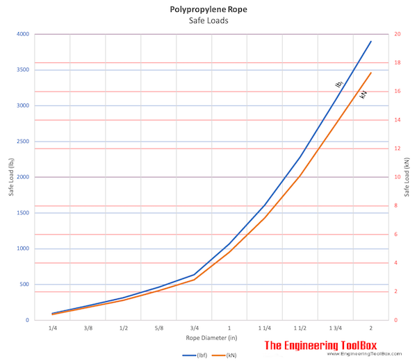
When calculating mass using F = Minimum Breaking Force, according to the wire rope’s diameter, you can determine the Minimum Breaking Massand therefore the wire’s max strength. When calculating mass using F = Safe Load according to the wire rope’s diameter, you can determine the Safe Load Mass,which is the advised load for this rope diameter.
The strands of a wire rope absorb the majority of the tensile force applied on the rope. Their design and manufacturing standards affect the level of fatigue resistance and resistance to abrasion. An easy way to understand which rope design is suitable for each purpose, is the wire rope classification.
Wire ropes are classified according to the number of strands in each construction and the number of wires in each strand. For example, a classification of 6X19 means that a wire rope of this type always has six strands, but its wires could be 15-26 per strand. This is because 19 is not the exact number of wires, but the classification of a wire number range.
Visual inspections are a common and fast way to assess wire rope condition. Both the standard and rotation resistant wire rope inspectionprocesscomply with the same four steps of examination. A ship’s crew can perform them as follows:
Steel wire rope distortion is obvious in most cases and can easily be identified by the inspector or the ship‘s crew. It usually occurs if load is suddenly applied or abruptly released (shock loading), or even if swift torque is forcefully induced.
Although not all of these deformations make the rope absolutely dangerous to use, they all may cause ropes to wear unevenly in time. This means inspections should take place more often, and distorted ropes should be handled with caution.
The rag and visual inspection is a good method for regular inspection intervals. The inspector pulls a rag along the rope trying to find broken wire cords. If the rug gets snagged by the rope, the inspector has to stop and assess the wire rope’s condition. Extreme caution should be exercised during the visual inspection, and under no circumstances should this method be the only one used to inspect wire ropes.
Tip: When you encounter a protruding wire end, bend it back and forth manually, until it separates from the wire. This will protect neighboring wires from wearing out.
Diameter reduction is a critical factor in steel wire rope wear and if not properly taken care of, it can result in rope breakage. Excessive abrasion, loss of core mass, corrosion or inner wire failure are all factors that contribute to diameter reduction.
To get an accurate measurement of the rope’s diameter, measure the rope at three different points at least 5 feet apart. Take the average of these three measurements to determine the true diameter.
Any measurements showing a reduction of ⅓ or more, indicate that a replacement should follow without delay. A diameter reduction of less than 1/3 still requires attention, and the inspector or the ship’s crew should be on guard in the next scheduled wire rope inspection.
Failure from abrasion or corrosion is a result of deficient deck equipment inspection or insufficient wire rope lubrication respectively. Internal corrosive damage is more difficult to identify than any other types of degradation. In most cases, the damage has progressed more than the external signs suggest.
Wire rope storage plays a significant role in the rope’s operation life.Wire rope corrosion and pitting can be avoided if ropes are safely stored in a clean, cool, dry and well-ventilated place. Steel wire ropes should not by any means rest on the floor, and should be protected from water, dust or any chemical fumes. Long term storage requires periodic greasing, turning the reel upside down for preventing grease dripping and possibly re-winding to another reel with larger inner tube diameter.
Wire ropes should be maintained with periodical lubrication. In order to prevent internal corrosion, a pressure lubricator is suggested to be used. In this case, a small amount of grease is used to lubricate the rope internally, while the deck stays grease-clean. Pressure lubricators clean the rope before they grease it so that the new grease enters a clean rope. The type of grease used is very important for maximum protection and greasing efficiency.
Steel wire ropes exposed to dirt, grime and other contaminants, have to be cleaned with a wire brush and petroleum (unless a pressure lubricator is used). Optimal cleaning of wire ropes can extend their service life and guarantee safe operations.
The reeling process is of high importance for the longevity of wire ropes. To protect them from being damaged, it is important that the surface of the drum is clean, smooth and dry. Improper reeling may cause wire-rope strands to spread or get flattened, when in contact with one another, as successive layers are being spooled and upper layers apply pressure on the lower ones.
Katradis S.A. offers a wide range of top quality wire ropes for shipping (mooring and hoisting operations), fishing and construction purposes. Our wire ropes have greater resistance to fatigue, and they distribute tension force equally among the rope strands. They are less likely to kink, providing higher staff safety and assuring operation success.

6×19 construction wire rope is available with either FC (fibre core) or WSC (wire strand core). When supplied with a wsc the rope is more commonly referred to as 7×19. The rope is very popular in diameters from 3mm to 16mm and is used on a variety of applications. 6×19 FC and 6×19 WSC (7×19) is very flexible in diameters 3mm to 6mm and is used for many requirements where wire ropes are running over pulleys. 7×19 construction is readily available in both galvanised and marine grade stainless steel.
Steel wire ropes have important applications in mine lifting, cable-stayed bridges, metallurgy, elevators, and so on. They are widely used due to their high strength, light weight, reliability, and efficiency [1]. Since wire ropes usually work in harsh environments, although they suffer from a variety of types of damage such as broken wire and wear, which affects the safety of production and even threatens the lives of workers [2]. To avoid accidents, manual inspection and regular replacement are generally used in engineering. However, manual inspection is time-consuming and laborious, and regular replacement usually causes great economic waste. According to a survey, more than 70% of replaced wire ropes still have initial breaking strength [3]. Therefore, it is of great importance to develop scientific and effective devices to inspect steel wire ropes.
There are two types of defects of steel wire ropes, loss of metallic cross-sectional area (LMA) and a localized fault (LF), and broken wire is the most typical outcome of LF. Among the various nondestructive testing techniques, magnetic flux leakage (MFL) method is most economical and effective for broken wire detection [4,5,6,7,8]. The basic principle of the MFL method is shown in Figure 1, where the permanent magnet magnetizes part of the wire rope to saturation, and a closed magnetic circuit is formed between the wire rope, the magnet and the yoke. When no damage is present, most of the magnetic induction lines pass through the inside of the wire rope. When there is a damage such as broken wire, the magnetic resistance of the damaged position increases, and part of the magnetic induction line leaks out to form the MFL. Magnetic sensitive elements are placed between the poles of the magnet to sense the MFL signal. The condition of the wire rope can be determined according to the received signal.
For decades, many experts and scholars have done a lot of research on the design of damage detecting sensors based on the MFL method [9,10,11,12,13]. Cao Y.N. et al. [9] proposed an approach for detecting LF of steel wire ropes using an annular array of Hall components. A back propagation (BP) network is used to classify the faults. This method can differentiate the degree and the width of local defects. Zhang J. et al. [10] applied the giant magneto-resistance (GMR) sensor to the detection of LF and LMA of the wire rope. Through the use of compressed sensing wavelet filtering and BP neural network, the accuracy and reliability of MFL sensor is improved. Wu B. [13] designed an MFL sensor based on tunnel magneto-resistive device. A blind hole with dimension of 0.3 mm in both depth and diameter is detectable for the sensor. The axial resolution to two adjacent notches with a width of 0.2 mm of the TMR-based MFL sensor can be less than 2.5 mm. However, arranging annular arrays of Hall components undoubtedly increases the complexity of the signal processing. Using magneto-resistive sensors can improve the sensitivity of the sensor, but it is difficult to be applied to actual inspections due to the micron-level requirements of the lift-off [13]. Therefore, designing a sensor that can be applied to the detection in actual engineering and is both simple and effective, has always been a problem for the condition monitoring of wire ropes.
The magnetic concentrating detection technology provides a new direction for the development of MFL sensors. The detection of wire ropes usually requires the arrangement of a plurality of magnetic sensitive elements. Especially for the large diameter wire ropes, it usually needs dozens of magnetic sensors, which greatly increases the difficulty of signal processing in the later stage. The magnetic concentrating principle can realize the leak-free detection of large diameter wire ropes through a small number of magnetic sensitive elements [14,15]. Kang et al. [14] theoretically analyzed the feasibility of magnetic concentrating detection. It is proved by calculation that the magnetic concentrator can collect the MFL and guide it into the Hall component through the bridge between the concentrators to realize the collection of weak leakage flux. At the same time, it can eliminate the strand-waveform noise of wire ropes and improve signal-to-noise ratio of the MFL signal. Wang et al. [15] analyzed the performance of the magnetic concentrators on collecting the MFL by finite element simulation and proposed the structure which is suitable for collecting the magnetic leakage flux. The structure was verified by experiments, which further promoted the development of the magnetic concentrating detection.
In this study, a sensor, which is constructed of ring-shaped magnets, a yoke, and a magnetic concentrator, is designed to detect broken wires of steel wire ropes. We optimized the structural parameters of the circumferential multi-circuit permanent magnet exciter (CMPME) and analyzed the performance of the magnetic concentrator on collecting MFL through the finite element method. Finally, the proposed sensor is applied in an experiment for broken wire detection. The induced MFL signal can be clearly recognized and the signal-to-noise ratio of the MFL signal is improved by discrete wavelet transform (DWT).
Actual operating loads may vary. NEVER exceed the recommended design factor of 20% of catalogue strength. Wire Rope must have the strength required to handle the maximum load plus a design factor. The design factor is the ratio of the breaking strength of the rope to the maximum working load.

Wire rope and cable are each considered a “machine”. The configuration and method of manufacture combined with the proper selection of material when designed for a specific purpose enables a wire rope or cable to transmit forces, motion and energy in some predetermined manner and to some desired end.
Two or more wires concentrically laid around a center wire is called a strand. It may consist of one or more layers. Typically, the number of wires in a strand is 7, 19 or 37. A group of strands laid around a core would be called a cable or wire rope. In terms of product designation, 7 strands with 19 wires in each strand would be a 7×19 cable: 7 strands with 7 wires in each strand would be a 7×7 cable.
Materials Different applications for wire rope present varying demands for strength, abrasion and corrosion resistance. In order to meet these requirements, wire rope is produced in a number of different materials.
Stainless Steel This is used where corrosion is a prime factor and the cost increase warrants its use. The 18% chromium, 8% nickel alloy known as type 302 is the most common grade accepted due to both corrosion resistance and high strength. Other types frequently used in wire rope are 304, 305, 316 and 321, each having its specific advantage over the other. Type 305 is used where non-magnetic properties are required, however, there is a slight loss of strength.
Galvanized Carbon Steel This is used where strength is a prime factor and corrosion resistance is not great enough to require the use of stainless steel. The lower cost is usually a consideration in the selection of galvanized carbon steel. Wires used in these wire ropes are individually coated with a layer of zinc which offers a good measure of protection from corrosive elements.
Cable Construction The greater the number of wires in a strand or cable of a given diameter, the more flexibility it has. A 1×7 or a 1×19 strand, having 7 and 19 wires respectively, is used principally as a fixed member, as a straight linkage, or where flexing is minimal.
Selecting Wire Rope When selecting a wire rope to give the best service, there are four requirements which should be given consideration. A proper choice is made by correctly estimating the relative importance of these requirements and selecting a rope which has the qualities best suited to withstand the effects of continued use. The rope should possess:Strength sufficient to take care of the maximum load that may be applied, with a proper safety factor.
Strength Wire rope in service is subjected to several kinds of stresses. The stresses most frequently encountered are direct tension, stress due to acceleration, stress due to sudden or shock loads, stress due to bending, and stress resulting from several forces acting at one time. For the most part, these stresses can be converted into terms of simple tension, and a rope of approximately the correct strength can be chosen. As the strength of a wire rope is determined by its, size, grade and construction, these three factors should be considered.
Safety Factors The safety factor is the ratio of the strength of the rope to the working load. A wire rope with a strength of 10,000 pounds and a total working load of 2,000 pounds would be operating with a safety factor of five.
It is not possible to set safety factors for the various types of wire rope using equipment, as this factor can vary with conditions on individual units of equipment.
The proper safety factor depends not only on the loads applied, but also on the speed of operation, shock load applied, the type of fittings used for securing the rope ends, the acceleration and deceleration, the length of rope, the number, size and location of sheaves and drums, the factors causing abrasion and corrosion and the facilities for inspection.
Fatigue Fatigue failure of the wires in a wire rope is the result of the propagation of small cracks under repeated applications of bending loads. It occurs when ropes operate over comparatively small sheaves or drums. The repeated bending of the individual wires, as the rope bends when passing over the sheaves or drums, and the straightening of the individual wires, as the rope leaves the sheaves or drums, causing fatigue. The effect of fatigue on wires is illustrated by bending a wire repeatedly back and forth until it breaks.
The best means of preventing early fatigue of wire ropes is to use sheaves and drums of adequate size. To increase the resistance to fatigue, a rope of more flexible construction should be used, as increased flexibility is secured through the use of smaller wires.
Abrasive Wear The ability of a wire rope to withstand abrasion is determined by the size, the carbon and manganese content, the heat treatment of the outer wires and the construction of the rope. The larger outer wires of the less flexible constructions are better able to withstand abrasion than the finer outer wires of the more flexible ropes. The higher carbon and manganese content and the heat treatment used in producing wire for the stronger ropes, make the higher grade ropes better able to withstand abrasive wear than the lower grade ropes.
Effects of Bending All wire ropes, except stationary ropes used as guys or supports, are subjected to bending around sheaves or drums. The service obtained from wire ropes is, to a large extent, dependent upon the proper choice and location of the sheaves and drums about which it operates.
A wire rope may be considered a machine in which the individual elements (wires and strands) slide upon each other when the rope is bent. Therefore, as a prerequisite to the satisfactory operation of wire rope over sheaves and drums, the rope must be properly lubricated.
Loss of strength due to bending is caused by the inability of the individual strands and wires to adjust themselves to their changed position when the rope is bent. Tests made by the National Institute of Standards and Technology show that the rope strength decreases in a marked degree as the sheave diameter grows smaller with respect to the diameter of the rope. The loss of strength due to bending wire ropes over the sheaves found in common use will not exceed 6% and will usually be about 4%.
The bending of a wire rope is accompanied by readjustment in the positions of the strands and wires and results in actual bending of the wires. Repetitive flexing of the wires develops bending loads which, even though well within the elastic limit of the wires, set up points of stress concentration.
The fatigue effect of bending appears in the form of small cracks in the wires at these over-stressed foci. These cracks propagate under repeated stress cycles, until the remaining sound metal is inadequate to withstand the bending load. This results in broken wires showing no apparent contraction of cross section.
Experience has established the fact that from the service view-point, a very definite relationship exists between the size of the individual outer wires of a wire rope and the size of the sheave or drum about which it operates. Sheaves and drums smaller than 200 times the diameter of the outer wires will cause permanent set in a heavily loaded rope. Good practice requires the use of sheaves and drums with diameters 800 times the diameter of the outer wires in the rope for heavily loaded fast-moving ropes.
It is impossible to give a definite minimum size of sheave or drum about which a wire rope will operate with satisfactory results, because of the other factors affecting the useful life of the rope. If the loads are light or the speed slow, smaller sheaves and drums can be used without causing early fatigue of the wires than if the loads are heavy or the speed is fast. Reverse bends, where a rope is bent in one direction and then in the opposite direction, cause excessive fatigue and should be avoided whenever possible. When a reverse bend is necessary larger sheaves are required than would be the case if the rope were bent in one direction only.
Stretch of Wire Rope The stretch of a wire rope under load is the result of two components: the structural stretch and the elastic stretch. Structural stretch of wire rope is caused by the lengthening of the rope lay, compression of the core and adjustment of the wires and strands to the load placed upon the wire rope. The elastic stretch is caused by elongation of the wires.
The structural stretch varies with the size of core, the lengths of lays and the construction of the rope. This stretch also varies with the loads imposed and the amount of bending to which the rope is subjected. For estimating this stretch the value of one-half percent, or .005 times the length of the rope under load, gives an approximate figure. If loads are light, one-quarter percent or .0025 times the rope length may be used. With heavy loads, this stretch may approach one percent, or .01 times the rope length.
The elastic stretch of a wire rope is directly proportional to the load and the length of rope under load, and inversely proportional to the metallic area and modulus of elasticity. This applies only to loads that do not exceed the elastic limit of a wire rope. The elastic limit of stainless steel wire rope is approximately 60% of its breaking strength and for galvanized ropes it is approximately 50%.
Preformed Wire Ropes Preformed ropes differ from the standard, or non-preformed ropes, in that the individual wires in the strands and the strands in the rope are preformed, or pre-shaped to their proper shape before they are assembled in the finished rope.
This, in turn, results in preformed wire ropes having the following characteristics:They can be cut without the seizings necessary to retain the rope structure of non-preformed ropes.
They are substantially free from liveliness and twisting tendencies. This makes installation and handling easier, and lessens the likelihood of damage to the rope from kinking or fouling. Preforming permits the more general use of Lang lay and wire core constructions.
Removal of internal stresses increase resistance to fatigue from bending. This results in increased service where ability to withstand bending is the important requirement. It also permits the use of ropes with larger outer wires, when increased wear resistance is desired.
Outer wires will wear thinner before breaking, and broken wire ends will not protrude from the rope to injure worker’s hands, to nick and distort adjacent wires, or to wear sheaves and drums. Because of the fact that broken wire ends do not porcupine, they are not as noticeable as they are in non-preformed ropes. This necessitates the use of greater care when inspecting worn preformed ropes, to determine their true condition.


 8613371530291