
wire rope calculation formula quotation
While it is virtually impossible to calculate the precise length of wire rope that can be spooled on a reel or drum, the following provides a sufficiently close approximation.
* This formula is based on uniform rope winding on the reel. It will not give correct results if the winding is non-uniform. The formula also assumes that there will be the same number of wraps in each layer. While this is not strictly correct, there is no appreciable error in the result unless the traverse of the reel is quite small relative to the flange diameter (“H”).
** The values given for “K” factors take normal rope oversize into account. Clearance (“x”) should be about 2 inches unless rope-end fittings require more.

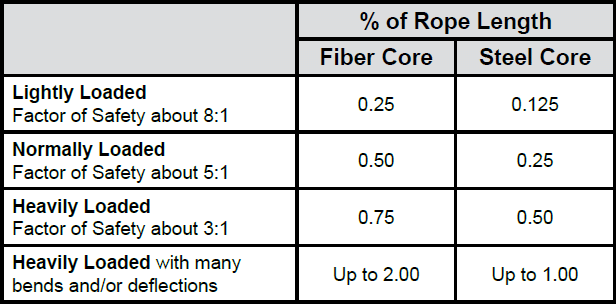
To obtain reasonable service life from your aircraft cable or wire rope, you must choose the optimal diameter of rope and sheave for your application. In general, the larger the size of the drum or pulley with respect to the wire diameter, the longer the service life. The opposite is also true: in general, the smaller the size of the drum or pulley with respect to your wire rope, the shorter the service life. Keep these relationships between cable, rope, and pulleys in mind when specifying the competence you use in your application.
The tables below provide the minimum recommended pulley diameter as well as the approximate bend radius of the rope. You"ll notice that the calculation is approximately half of the minimum recommended pulley tread diameter. Whether running fully over the sheave or drum, or some fraction thereof, check your design against the recommendations to better understand the service life you can expect in relation to the other factors involved.
Rope strength is a misunderstood metric. One boater will talk about tensile strength, while the other will talk about working load. Both of these are important measurements, and it’s worth learning how to measure and understand them. Each of these measurements has different uses, and here we’re going to give a brief overview of what’s what. Here’s all you need to know about rope strength.
Each type of line, natural fiber, synthetic and wire rope, have different breaking strengths and safe working loads. Natural breaking strength of manila line is the standard against which other lines are compared. Synthetic lines have been assigned “comparison factors” against which they are compared to manila line. The basic breaking strength factor for manila line is found by multiplying the square of the circumference of the line by 900 lbs.
When you purchase line you will buy it by its diameter. However, for purposes of the USCG license exams, all lines must be measured by circumference. To convert use the following formula.
As an example, if you had a piece of ½” manila line and wanted to find the breaking strength, you would first calculate the circumference. (.5 X 3.14 = 1.57) Then using the formula above:
To calculate the breaking strength of synthetic lines you need to add one more factor. As mentioned above, a comparison factor has been developed to compare the breaking strength of synthetics over manila. Since synthetics are stronger than manila an additional multiplication step is added to the formula above.
Using the example above, letÂ’s find the breaking strength of a piece of ½” nylon line. First, convert the diameter to the circumference as we did above and then write the formula including the extra comparison factor step.
Just being able to calculate breaking strength doesn’t give one a safety margin. The breaking strength formula was developed on the average breaking strength of a new line under laboratory conditions. Without straining the line until it parts, you don’t know if that particular piece of line was above average or below average. For more information, we have discussed the safe working load of ropes made of different materials in this article here.
It’s very important to understand the fundamental differences between the tensile strength of a rope, and a rope’s working load. Both terms refer to rope strength but they’re not the same measurement.
A rope’s tensile strength is the measure of a brand-new rope’s breaking point tested under strict laboratory-controlled conditions. These tests are done by incrementally increasing the load that a rope is expected to carry, until the rope breaks. Rather than adding weight to a line, the test is performed by wrapping the rope around two capstans that slowly turn the rope, adding increasing tension until the rope fails. This test will be repeated on numerous ropes, and an average will be taken. Note that all of these tests will use the ASTM test method D-6268.
The average number will be quoted as the rope’s tensile strength. However, a manufacturer may also test a rope’s minimum tensile strength. This number is often used instead. A rope’s minimum tensile strength is calculated in the same way, but it takes the average strength rating and reduces it by 20%.
A rope’s working load is a different measurement altogether. It’s determined by taking the tensile strength rating and dividing it accordingly, making a figure that’s more in-line with an appropriate maximum load, taking factors such as construction, weave, and rope longevity into the mix as well. A large number of variables will determine the maximum working load of a rope, including the age and condition of the rope too. It’s a complicated equation (as demonstrated above) and if math isn’t your strong point, it’s best left to professionals.
However, if you want to make an educated guess at the recommended working load of a rope, it usually falls between 15% and 25% of the line’s tensile strength rating. It’s a lotlower than you’d think. There are some exceptions, and different construction methods yield different results. For example, a Nylon rope braided with certain fibers may have a stronger working load than a rope twisted out of natural fibers.
For safety purposes, always refer to the information issued by your rope’s manufacturer, and pay close attention to the working load and don’t exceed it. Safety first! Always.
If you’re a regular sailor, climber, or arborist, or just have a keen interest in knot-tying, be warned! Every knot that you tie will reduce your rope’s overall tensile strength. Some knots aren’t particularly damaging, while others can be devastating. A good rule of thumb is to accept the fact that a tied knot will reduce your rope’s tensile strength by around 50%. That’s an extreme figure, sure, but when it comes to hauling critical loads, why take chances?
Knots are unavoidable: they’re useful, practical, and strong. Splices are the same. They both degrade a rope’s strength. They do this because a slight distortion of a rope will cause certain parts of the rope (namely the outer strands) to carry more weight than others (the inner strand). In some cases, the outer strands end up carrying all the weight while the inner strands carry none of it! This isn’t ideal, as you can imagine.
Some knots cause certain fibers to become compressed, and others stretched. When combined together, all of these issues can have a substantial effect on a rope’s ability to carry loads.
Naturally, it’s not always as drastic as strength loss of 50% or more. Some knots aren’t that damaging, some loads aren’t significant enough to cause stress, and some rope materials, such as polypropylene, Dyneema, and other modern fibers, are more resilient than others. Just keep in mind that any knots or splices will reduce your rope’s operations life span. And that’s before we talk about other factors such as the weather or your rope care regime…
It is also very important to know the weight calculation formula for stainless steel wire ropes. Whether you are in the industry or animal fences, it is inevitable to quote the formula for the weight of stainless steel wire rope. Calculate the exact weight and know how to arrange it.
Calculation formula: stainless steel wire rope (KG) 0.004 × diameter (mm) × diameter (mm) × length (m) = kg / m (for 7 * 7 7 * 19 7 * 37) Example: 3mm7 * 7 wire rope per meter weight = 0.004×3×3x1=0.036kg
1Stainless steel wire mesh. It is used for screening and filtration under acid and alkali environmental conditions. It is used in the oil industry as a mud network, chemical chemical fiber industry as a sieve, and electroplating industry as a pickling net. The factory can design and manufacture various types of products according to user needs. ...
3: Stainless steel wire mesh is used for screening and filtration under acid and alkali environmental conditions. The petroleum industry is used as mud net, chemical chemical fiber industry, as sieve screen, electroplating...

One of the requests we frequently receive is to include an overall diameter (OD) of the customized cable bundles being quoted. This request comes up often since electrical contractors need to be able to estimate if their plans are in sync with one another, and a ballpark estimate gives them a sense that their initial assumptions and calculations are correct, or if they want to add a little margin of error in the costs of the conduit, or if they really have to crunch the numbers to ensure everything fits within the National electrical code (NEC) standards.
As an OEM that reprocesses premanufactured wire, we do not make the wire itself, and each manufacturer has its own tolerances in terms of OD for each wire jacket type.
Here we use averages of manufacturer specs to give us the ability to estimate the OD of the wire bundle for our own necessary calculations which is reel capacity. The calculation itself is a matter of mathematics, and with known data can be formulated and calculated using simple excel spreadsheets.
This calculation helps determine if the conduit planned is the correct size or not. The easiest way to actually measure the cable bundle is with a small measuring tool called an OD-Tape. OD-Tapes are used in the electrical field and plumbing fields to measure both length and overall outside diameter. To estimate the bundle, cut one 3-inch piece for each conductor in your bundle, tape them all together and use the OD tape to measure the outside.
2. Utilize a standard formula to calculate the cross-section area of that one wire using the area formula for a circle, i.e., area equals the square of the diameter multiplied by 3.14 (pi) divided by four. As an example, a2-inchwire would have an area of 3.14 square inch because 2 x 2 x 3.14 divided by 4 = 3.14.
4. Multiply the number of wires by the area of one wire. This will give you the total area. To continue the example, suppose you had 30 same-size wires. The total area would be 94.2 square inches (3.14 x 30). This example would be for a bundle of the same sized wires in the bundle.For a composite bundle with multiple AWG sized conductors it is only slightly more complicated. To calculate you simply follow the area calculations for each size of wire, that is, calculate one wire’s area and multiply it by the number of equal-sized wires (so if #14 is 10 wires then multiply the OD by 10; If #12 is 20 thenmultiply the OD by 20). Finally, you would add all the areas together to compute the total area.
5. Calculate the diameter of the bundle by using the same area formula, modified to solve for diameter: Diameter = square root (4 area / 3.14) In the example: Diameter = square root (4 x (94.2 / 3.14) = 4 x 30=120)
In the field, the electrical contractor has to use other formulas and computations to determine fill factors and OD changes for any given bend radius of the cable. Some cables retain their flexibility, others have push outs that widen the OD in one direction and flatten it in another. It is always good to review the numbers before ordering and pulling the cable into a particular conduit.
In this article, we outline important technical topics related to wire rope. This information has been sourced from and approved by Bridon American. Use the outline to skip to specific sections:
Any assembly of steel wires spun into a helical formation, either as a strand or wire rope (when subjected to a tensile load) can extend in three separate phases, depending on the magnitude of the applied load.
At the commencement of loading a new rope, extension is created by the bedding down of the assembled wires with a corresponding reduction in overall diameter. This reduction in diameter is accommodated by a lengthening of the helical lay. When sufficiently large bearing areas have been generated on adjacent wires to withstand the circumferential compressive loads, this mechanically created extension ceases and the extension in Phase 2 commences. The Initial Extension of any rope cannot be accurately determined by calculation and has no elastic properties.
The practical value of this characteristic depends upon many factors, the most important being the type and construction of rope, the range of loads and the number and frequency of the cycles of operation. It is not possible to quote exact values for the various constructions of rope in use, but the following approximate values may be employed to give reasonably accurate results.
Following Phase 1, the rope extends in a manner which complies approximately with Hookes Law (stress is proportional to strain) until the limit of proportionality or elastic limit is reached.
It is important to note that wire ropes do not possess a well defined Young’s Modulus of Elasticity, but an ‘apparent’ Modulus of Elasticity can be determined between two fixed loads.
By using the values given, it is possible to make a reasonable estimate of elastic extension, but if greater accuracy is required, it is advisable to carry out a modulus test on an actual sample of the rope. As rope users will find it difficult to calculate the actual metallic steel area, the values can be found in the Wire Rope Users Manual or obtained from Bridon Engineering.
The permanent, non-elastic extension of the steel caused by tensile loads exceeding the yield point of the material. If the load exceeds the Limit of Proportionality, the rate of extension will accelerate as the load is increased until a loading is reached at which continuous extension will commence, causing the wire rope to fracture without any further increase of load.
The coefficient of linear expansion (∝) of steel wire rope is (6.94 x 10⁻⁶ per °F) and therefore the change in length of 1 foot of rope produced by a temperature change of t (°F) would be:
Example: What will be the total elongation of a 200 ft. length of 1-1/8″ diameter Blue Strand 6 x 41 IWRC wire rope at a tension of 20,000 Ibs. and with an increase in temperature of 20°F?
In addition to bending stresses experienced by wire ropes operating over sheaves or pulleys, ropes are also subjected to radial pressure as they make contact with the sheave. This pressure sets up shearing stresses in the wires, distorts the rope’s structure and affects the rate of wear of the sheave grooves. When a rope passes over a sheave, the load on the sheave bearing results from the tension in the rope and the angle of rope contact. It is independent of the diameter of the sheave.
Assuming that the rope is supported in a well fitting groove, then the pressure between the rope and the groove is dependent upon the rope tension and diameter, but is independent of the arc of contact.
It must be realized that this method of estimation of pressure assumes that the area of contact of the rope in the groove is on the full rope diameter, whereas in fact only the crowns of the outer wires are actually in contact with the groove. It is estimated that the local pressures at these contact points may be as high as five times those calculated. If the pressure is high, the compressive strength of the material in the groove may be insufficient to prevent excessive wear and indentation, and this in turn will damage the outer wires of the rope and effect its working life.
As with bending stresses, stresses due to radial pressure increase as the diameter of the sheave decreases. Although high bending stresses generally call for the use of flexible rope constructions having relatively small diameter outer wires, these have less ability to withstand heavy pressures than do the larger wires in the less flexible constructions. If the calculated pressures are too high for the particular material chosen for the sheaves or drums or indentations are being experienced, consideration should be given to an increase in sheave or drum diameter. Such a modification would not only reduce the groove pressure, but would also improve the fatigue life of the rope.
The pressure of the rope against the sheave also causes distortion and flattening of the rope structure. This can be controlled by using sheaves with the correct groove profile, which, for general purposes, suggests a recommended groove diameter of nominal rope diameter +6%. The profile at the bottom of the groove should be circular over an angle of approximately 120° and the angle of flare between the sides of the sheave should be approximately 52°.
Bend fatigue testing of ropes usually consists of cycling a length of rope over a sheave while the rope is under a constant tension. As part of their ongoing development program, Bridon has tested literally thousands of ropes in this manner over the years on their own in-house design bend testing equipment.
Through this work, Bridon has been able to compare the effects of rope construction, tensile strength, lay direction, sheave size, groove profile and tensile loading on bend fatigue performance under ideal operating conditions. At the same time it has been possible to compare rope life to discard criteria (e.g. as laid down in ISO 4309) with that to complete failure of the rope, i.e. to the point where the rope has been unable to sustain the load any longer. As part of the exercise, it has also been possible to establish the residual breaking strength of the rope at discard level of deterioration.
What needs to be recognized, however, is that very few ropes operate under these controlled operating conditions, making it very difficult to use this base information when attempting to predict rope life under other conditions. Other influencing factors, such as dynamic loading, differential loads in the cycle, fleet angle, reeving arrangement, type of spooling on the drum, change in rope direction, sheave alignment, sheave size and groove profile, can have an equally dramatic effect on rope performance.
If designers or operators of equipment are seeking optimum rope performance or regard bending fatigue life as a key factor in the operation of equipment, such information can be provided by Bridon for guidance purposes.
Wire ropes are manufactured slightly larger than the nominal diameter. The maximum allowable oversize tolerances provided by industry standards are shown in the following table:
Under certain circumstances it may be necessary to use a swivel in a lifting system to prevent rotation of the load. This is typically done for employee safety considerations. It is possible however, that the use of a swivel will have an adverse affect on rope performance and may, in some cases, damage the wire rope.
The type of swivel that causes the most concern from the standpoint of the wire rope is the independent anti-friction swivel that attaches directly to the rope. The purpose of using a swivel in a lifting system is to prevent rotation of the load. This then allows the wire rope to rotate. Excessive rope rotation can damage a wire rope.
To assist in determining whether or not a swivel should be used in the lifting system, the following recommendations should be considered. It must also be recognized that the rotation characteristics of different types and constructions of wire rope vary considerably. The following types and constructions of wire rope are grouped according to their rotation characteristics.
These rope constructions will rotate excessively with one end free to rotate, and the rope will unlay and distort and be easily damaged with a loss of rope breaking force.Blue Strand 6 x 19 and 6 x 36 Class Lang Lay
Wire rope constructions having high rotation characteristics when used in single part reeving may require a swivel in the system to prevent rotation in certain operating conditions. However, this should be done only when employee safety is the issue.
These rope constructions, when used in a reeving system with one end free to rotate, will have a high level of rotation. This will cause the rope to unlay and, to some degree, distortion of the rope will occur.Blue Strand 6 x 19 and 6 x 36—Class Regular Lay
The ropes in this Group are designed with an inner rope that is laid in the opposite direction to the outer strands to provide a medium resistance to rotation. Ropes with medium rotation characteristics are used with a swivel in single part reeving applications. However, a swivel is not recommended for multiple part hoisting applications or in any application where the swivel is not necessary for safety reasons. If it is necessary to use a swivel, the rope must be operating at a design factor of 5 or greater, must not be shock loaded and must be inspected daily by a qualified person for distortion.
It should be noted that if a swivel is used on conjunction with Group 3a ropes, rope service life might be reduced due to increased internal wear between the outer strands and the inner rope.Group 3aEndurance 8RR Rotation Resistant
Wire ropes having low rotation characteristics used in either single or multiple part reeving may be used with a swivel. The reason for this is that the ropes will exhibit very little, if any, rotation when used at the proper design factor. Application parameters, such as a fleet angle, may induce turn into a wire rope that can be relieved by the use of a swivel. However, if the application does not induce any turn into the rope, or if a swivel is not beneficial to the performance of the rope, the swivel may not be necessary.Endurance 35 LS
If the drum incorporates helical grooving, the helix angle of the groove needs to be added or subtracted from the fleet angle as described above to determine the actual fleet angle experienced by the rope.
When spooling rope onto a drum, it is generally recommended that the fleet angle is limited to between 0.5° and 2.5°. If the fleet angle is too small, i.e. less than 0.5°, the rope will tend to pile up at the drum flange and fail to return across the drum. In this situation, the problem may be alleviated by introducing a ‘kicker’ device or by increasing the fleet angle through the introduction of a sheave or spooling mechanism.
If the rope is allowed to pile up, it will eventually roll away from the flange, creating a shock load in both the rope and the structure of the mechanism, an undesirable and unsafe operating condition.
Excessively high fleet angles will return the rope across the drum prematurely, creating gaps between wraps of rope close to the flanges, as well as increasing the pressure on the rope at the cross-over positions.
Even where helical grooving is provided, large fleet angles will inevitably result in localized areas of mechanical damage as the wires ‘pluck’ against each other. This is often referred to as ‘interference’, but the amount can be reduced by selecting a Langs lay rope if the reeving allows. The “interference” effect can also be reduced by employing a Dyform rope, which offers a much smoother exterior surface than conventional rope constructions.
Where a fleet angle exists as the rope enters a sheave, it initially makes contact with the sheave flange. As the rope continues to pass through the sheave it moves down the flange until it sits in the bottom of the groove. In doing so, even when under tension, the rope will actually roll, as well as slide. As a result of the rolling action, the rope is twisted, i.e. turn is induced into or out of the rope, either shortening or lengthening the lay length of the outer layer of strands. As the fleet angle increases, so does the amount of twist.
To reduce the amount of twist to an acceptable level, the fleet angle should be limited to 2.5° for grooved drums and 1.5° for plain drums and when using Rotation Resistant, ropes the fleet angle should be limited to 1.5°.
However, for some crane and hoist applications, it is recognized that for practical reasons. It is not always possible to comply with these general recommendations, in which case, the rope life could be affected.
The problem of torsional instability in crane hoist ropes would not exist if the ropes could be perfectly torque balanced under load. The torque generated in a wire rope under load is usually directly related to the applied load by a constant ‘torque factor’. For a given rope construction, the torque factor can be expressed as a proportion of the rope diameter and this has been done below.
Variation with rope construction is relatively small and hence the scope for dramatically changing the stability of a hoisting system is limited. Nevertheless, the choice of the correct rope can have a deciding influence, especially in systems which are operating close to the critical limit. It should be noted that the rope torque referred to here is purely that due to tensile loading. No account is taken of the possible residual torque due, for example, to rope manufacture or installation procedures.
Torsional Stability and the Cabling Graph are two methods which can be used to determine torsional stability or the tendency of the rope to cable. The torque factors quoted are approximate maximum values for the particular constructions. To calculate the torque value for a particular rope size, multiply by the nominal rope diameter.
The torsional characteristics of wire rope will have the effect of causing angular displacement of a sheave block when used in multi-fall reeving arrangements. The formula below gives a good approximation under such arrangements.
The preceding equations are all relative to a simple two part reeving. For more complex systems, a similar approach may be used if account is taken of the different spacings of the ropes.
The equations assume that rope is torque-free in the noload condition, therefore, induced torque during or immediately after installation will adversely influence the calculated effect.
The above data assumes a constant torque value which is a valid assumption for a new rope. Wear and usage can have a significant effect on the torque value, but practical work shows that under such circumstances, the torque value will diminish, thus improving the stability of the arrangement. Some arrangements may be of such complexity that the evaluation demands a computer study.
Assuming a pedestal crane working on two falls is roped with 20mm diameter DYFORM 34LR and the bottom block carries a sheave of 360mm diameter with the falls parallel:
If the rope is new (worst condition) and no account is taken of block weight and friction then angular displacement for a height of lift of 30 meters is given by:
Field research jointly conducted by the Wire Rope Technical Board and the Power Crane and Shovel Association has shown that cabling of the rope parts in a multiple part reeved hoisting arrangement is controlled by several factors. The following calculations and graphs can be used to determine when and if cabling will occur on multiple part reeved hoisting arrangements.
Various constructions of rope shown on the graph indicate the limited conditions for torsional stability with the angular displacement of the hoist block to a maximum of 90 degrees. When the operating conditions for a particular installation give a resultant above the appropriate band, then cabling of the falls will most likely occur. If the operating conditions give a resultant below any particular band, the cabling of the falls will most likely not occur. If the operating conditions for any particular installation fall within the band, cabling is unpredictable.

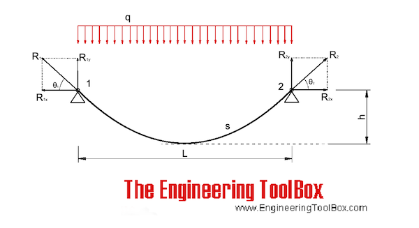
After obtaining the integral solution of formula (1) and considering the boundary conditions (x = 0, y = 0) and (x = l, y = h), the catenary cable shape can be obtained as follows.
In the formula, the parameter \(a = arsh\left[ {\frac{qh}{{2H \cdot \backslash sh\left( {\frac{ql}{{2H}}} \right)}}} \right] + \frac{ql}{{2H}}\) can be obtained by integrating the length s of the catenary cable from Eq. (3) as follows.
From Eqs. (2) to (6), it can be seen that given the tension T of one end cable, the horizontal component H and the cable shape y are coupled with each other. Thus, the unstressed cable length S0 can be determined by iterative calculation. In the calculation, the iterative parameter can be selected as the horizontal component force H, and its initial iterative value H0 is often taken as the component force of the tower end cable tension T along the chord line.
The approximate analytical algorithm assumes that the load and deformation of several main cables of the cable bridge are uniform, and it is equivalent to a single cable plane model, as shown in Fig. 1. It is assumed that the cable shape of the main span is parabolic, and both ends are hinged at the theoretical intersection points A and B of the main cable axis at the saddle. The influence of the horizontal dip angle and the sag of the main cable of the anchor span was ignored, and a horizontal cable force was used to replace the axial cable force of all sections of the anchor cable span and main span. Based on the relationship between the mechanical balance and the physical properties of the materials, according to the geometric conditions of equal cable suspension speed of the whole cable for the same cable bridge under any two load conditions, a cubic algebraic equation of horizontal cable force under the calculated load state is obtained. Finally, the main cable shape is obtained from the obtained balance conditions of the horizontal cable force and moment [11].
A wire rope pitch measuring method according to an embodiment of the present invention is obtained by using a wire rope pitch measuring horizontal base 11 shown in FIG. 1 and a wire rope pitch measuring device 13 shown in FIGS. In this measurement method, a wire rope receiving groove 12 is linearly formed on the upper surface of the horizontal base 11 for measuring the wire rope pitch. The wire rope accommodating groove 12 accommodates a wire rope that is an object to be measured, and a cross section in the depth direction is formed in a V shape.
The wire rope pitch measuring device 13 is set above the wire rope receiving groove 12 when measuring the wire rope pitch, and includes a laser displacement sensor 14, a linear guide 15, a ball screw 16, an encoder 17, an arithmetic device 18, and a display. 19, end plates 20a and 20b, positioning members 22a and 22b, a top plate 26 and a slide operation handle 28 are provided.
The laser displacement sensor 14 is disposed so as to face the side surface of the wire rope accommodated in the wire rope accommodation groove 12, and the distance from the laser displacement sensor 14 to the surface of the wire rope by irradiating the side surface of the wire rope with laser light. Is measured optically. The laser light 32 emitted from the laser displacement sensor 14 has a slit shape elongated in the radial direction of the wire rope, receives the laser light reflected along the cross-sectional shape in the radial direction of the wire rope on the surface of the wire rope, and receives the wire. The displacement in the irradiation direction of the laser beam on the rope surface is measured over a range of 20 mm, for example (see FIG. 10).
ボールねじ16は、スライダ151の直線運動を回転運動に変換するものであって、スライダ151の移動量に応じて回転するねじ軸161(図6参照)を有している。The linear guide 15 guides the laser displacement sensor 14 in the length direction of the wire rope housed in the wire rope housing groove 12, and the laser displacement sensor 14 is moved to the slider 151 (see FIG. 6) of the linear guide 15. Is installed.
The computing device 18 computes the pitch of the wire rope based on the signal output from the laser displacement sensor 14 and the signal output from the encoder 17, and is composed of, for example, a microcomputer.
位置決め部材22a,22bは端板20a,20bの外面に設けられ、凹曲面23、水平軸24a,24b及び支持脚25a,25bをそれぞれ有している。The display 19 digitally displays the calculation result of the calculation device 18 and is composed of, for example, a liquid crystal display panel.
The end plates 20a and 20b are provided perpendicular to both ends in the length direction of the linear guide 15 and have setting handles 21a and 21b formed by bending a rod-shaped metal member into a U-shape. These setting handles 21a and 21b are for setting the wire rope pitch measuring device 13 above the wire rope housing groove 12, and are mounted on the outer surfaces of the end plates 20a and 20b.
The concave curved surface 23 is for positioning the laser displacement sensor 14 and the linear guide 15 above the wire rope housing groove 12, and is curved in an arc shape with respect to the wire rope housed in the wire rope housing groove 12. . Then, by pressing the concave curved surfaces 23 of the pair of positioning members 22a and 22b against the wire rope, the length direction of the wire rope 30 and the guide direction of the linear guide 15 substantially coincide with each other.
支持脚25a,25bは、レーザ変位センサ14やリニアガイド15をワイヤロープ収容溝12の上方に水平に支持するためのもので、水平軸24a,24bの軸回りに回動自在に軸支されている。支持脚25a,25bは、それぞれに設けた歯車(図示せず)が噛み合わされて、連動して逆方向に回動するように構成されている。The horizontal shafts 24 a and 24 b support the support legs 25 a and 25 b so as to be freely opened and closed, and project horizontally from the outer surfaces of the positioning members 22 a and 22 b along the wire rope housing grooves 12.
The support legs 25a and 25b are used to horizontally support the laser displacement sensor 14 and the linear guide 15 above the wire rope housing groove 12, and are pivotally supported around the horizontal axes 24a and 24b. Yes. The support legs 25a and 25b are configured so that gears (not shown) provided on the support legs 25a and 25b are engaged with each other and rotated in the reverse direction in conjunction with each other.
スライド操作用取っ手28は、ワイヤロープ収容溝12に収容されたワイヤロープの長さ方向にレーザ変位センサ14をスライド操作するためのものであって、レーザ変位センサ14の側面に装着されている。The top plate 26 is formed in a rectangular shape with dimensions of, for example, a width of 63 mm and a length of 685 mm. The top plate 26 is fixed to the upper surface of the linear guide 15 and has a carrying handle 27 formed by bending a bar-shaped metal member into a U-shape. The carrying handle 27 is for carrying the wire rope pitch measuring device 13 and is attached to the center of the top surface of the top plate 26.
The slide operation handle 28 is used to slide the laser displacement sensor 14 in the length direction of the wire rope housed in the wire rope housing groove 12, and is attached to the side surface of the laser displacement sensor 14.
When the wire rope pitch is measured using such a wire rope pitch measuring device 13, as shown in FIG. 8, a wire rope 30 formed by twisting a plurality of (for example, six) strands 31 is used as a wire rope. It is accommodated in a wire rope accommodation groove 12 formed on the upper surface of the horizontal base 11 for pitch measurement. Next, as shown in FIG. 9, the wire rope pitch measuring device 13 is set above the wire rope housing groove 12. Specifically, after opening the supporting legs 25a and 25b supported by the horizontal shafts 24a and 24b, the concave curved surface 23 formed on the positioning members 22a and 22b is pressed against the wire rope 30 from above. Then, in this state, the support legs 25a and 25b are closed, and the tips of the support legs 25a and 25b are brought into contact with the upper surface of the wire rope pitch measuring horizontal base 11 across the wire rope pitch receiving groove 12, so that the linear guide 15 is The wire rope pitch measuring device 13 is set above the wire rope housing groove 12 so as to be.
When the wire rope pitch measuring device 13 is set above the wire rope receiving groove 12 in this way, the laser beam 32 is applied to the wire rope 30 from the laser displacement sensor 14 of the wire rope pitch measuring device 13 as shown in FIG. , And the displacement of the surface of the wire rope 30 is measured by the laser displacement sensor 14. At the same time, the laser displacement sensor 14 is moved in the length direction of the wire rope 30 by operating the slide operation handle 28.
At this time, as shown in FIG. 10, the laser displacement sensor 14 irradiates the wire rope 30 with a slit-like laser beam 32 that is elongated in the radial direction of the wire rope 30 (direction substantially orthogonal to the length direction). . At this time, the calculation device 18 of the wire rope pitch measurement device 13 calculates the pitch of the wire rope 30 based on the signal output from the laser displacement sensor 14 and the signal output from the encoder 17, and calculates the result. Displayed on the display 19 as the pitch of the wire rope 30.
なお、図11、図12においては、ワイヤロープ30が、6本のストランド31a,31b,31c,31d,31e,31fを螺旋状に撚り合わせた場合を例にとって示してある。A method of calculating the wire rope pitch by the calculation device 18 will be described with reference to FIGS. A case where the laser beam 32 is not slit-shaped will be described as a comparison.
FIG. 11 shows the wire rope pitch in the case of using the laser displacement sensor that irradiates slit-shaped laser light according to the embodiment of the present invention and in the case of using the laser displacement sensor that irradiates linear laser light as a comparison method. It is explanatory drawing explaining a measuring method. FIG. 11A is a plan view of the wire rope 30 irradiated with the laser light as seen from the laser light irradiation direction, and shows a case where the slide movement direction of the laser displacement sensor coincides with the center line direction of the wire rope. Show. FIG. 11B is a graph showing the relationship between the displacement measurement value by the laser displacement sensor and the slide movement amount (length direction position) of the laser displacement sensor in the case shown in FIG. FIG. 11C is a plan view of the wire rope 30 irradiated with laser light as seen from the laser light irradiation direction, and the slide movement direction of the laser displacement sensor is shifted from the center line direction of the wire rope by an angle θ. Show the case. 12A, 12B, and 12C show a BB cross-sectional view, a CC cross-sectional view, and a DD cross-sectional view in FIG. 11A, respectively.
図11(b)の上段は、スリット状のレーザ光32をワイヤロープ30の長さ方向に移動させたときの、レーザ変位センサの長さ方向位置xと変位計測値Lとの関係を示すグラフである。図11(a)と図11(b)の上段のグラフとを比較してわかるように、1つのストランド31aで変位を計測している間に、測定点がb1→c1→d1のように変化し、これに伴い変位計測値Lとレーザ変位センサの長さ方向位置xとの関係を示す曲線は山形の曲線となる。測定点がストランド31a,31b,31d,…と移る毎にそれぞれ山形の曲線を示す。例えば6ストランドのワイヤの場合、1つ目の山の頂点c1から7つ目の山の頂点c7までの移動距離を求めることでワイヤロープのピッチP1を算出できる。As shown in FIG. 11, the wire rope 30 is irradiated with a slit-like laser beam 32 elongated in the radial direction of the wire rope having a width h in the radial direction of the wire rope. In this state, the laser displacement sensor 14 is moved to the linear guide 15. Slide in the guide direction. At this time, since the laser beam 32 applied to the surface of the wire rope 30 moves in the direction of the arrow X, the movement locus of the laser beam 32 becomes a hatched movement locus 32a in the drawing. The laser displacement sensor 14 uses a point on the wire rope closest to the laser displacement sensor as a measurement point within the range where the slit-shaped laser beam 32 is irradiated.
The slit-shaped laser light 32 elongated in the radial direction of the wire rope irradiated from the laser displacement sensor 14 to the wire rope 30 is irradiated from the laser displacement sensor 14 so as to be substantially orthogonal to the axial direction of the wire rope 30. Therefore, the laser beam 32 is irradiated on the side surface of the wire rope 30 along the radial cross section of the wire rope 30. The laser displacement sensor 14 receives the laser beam 32 reflected along the radial cross section of the wire rope 30.
The displacement of the side surface of the wire rope 30 is measured using the position on the side surface of the wire rope 30 where the distance between the laser displacement sensor 14 and the side surface of the wire rope 30 is the shortest from the received laser light as a displacement measurement point. For example, when the slit laser beam 32 is irradiated on the line BB in FIG. 11, the distance l b1 between the laser displacement sensor 14 and the point b 1 is the shortest as shown in FIG. The irradiation position b 1 at this shortest distance is set as a displacement measurement point. When the laser displacement sensor 14 is moved in the direction of the arrow X and the laser beam 32 is irradiated on the line CC in FIG. 11, the point c 1 from the laser displacement sensor 14 is shown in FIG. Is the shortest distance l c1 , and therefore, c 1 point is set as a displacement measurement point. Further, when the laser displacement sensor 14 is moved in the arrow X direction and the laser beam 32 is irradiated on the line DD in FIG. 11, the distance l d1 from the laser displacement sensor 14 to the point d 1 is the shortest. Therefore, d 1 point is set as a displacement measurement point. Thus, the displacement L of each measurement point is measured while moving the laser displacement sensor 14 in the arrow X direction.
For example, as shown in FIG. 12A, the displacement L is determined as a reference position at a position away from the laser displacement sensor 14 by a predetermined distance L 0 , and a measured value from L 0 (in the case of FIG. 12A). It is obtained by subtracting l b1 ). Thus, as the laser displacement sensor 14 is moved in the length direction of the wire rope 30, the measurement point is moved in the width direction of the wire rope. The movement trajectory of the point is as indicated by the alternate long and short dash line Y in FIG. When the measurement point moves in the Y direction, that is, when the measurement point moves as b 1 point → c 1 point → d 1 point in FIG. 11A, the distance between the laser displacement sensor 14 and the wire rope surface also changes. and measuring the displacement value L becomes maximum at a point c.
The upper part of FIG. 11B is a graph showing the relationship between the position x in the length direction of the laser displacement sensor and the displacement measurement value L when the slit-shaped laser light 32 is moved in the length direction of the wire rope 30. It is. As can be seen by comparing FIG. 11 (a) and the upper graph of FIG. 11 (b), the measurement point is b 1 → c 1 → d 1 while measuring the displacement with one strand 31a. Accordingly, the curve indicating the relationship between the displacement measurement value L and the position x in the length direction of the laser displacement sensor is a mountain-shaped curve. Each time the measurement point moves to the strands 31a, 31b, 31d,. For example, in the case of a 6-strand wire, the wire rope pitch P 1 can be calculated by determining the moving distance from the first crest apex c 1 to the seventh crest apex c 7 .
演算装置18は、エンコーダ17から出力されたリニアガイド15のスライド移動量(長さ方向位置)xと、それに対応したレーザ変位センサ14により計測した変位計測値Lとを記録する。次に、図11(b)の上段に示すようなスライド移動量(長さ方向位置)xと変位計測位置Lの曲線とから、それぞれ山形について最高点c(c1,c2,c3,…,ci,…)(以下、山形の最高点をピッチ測定点cとも言う。)における長さ方向変位x(x1,x2,x3,…,xi,…)を求め、例えばワイヤロープ30が6ストランドのワイヤロープである場合には、xi+6−xiを算出することで、ワイヤロープピッチPを求める。The arithmetic device 18 records the slide movement amount (length direction position) x of the linear guide 15 output from the encoder 17 and the displacement measurement value L measured by the laser displacement sensor 14 corresponding thereto. Next, from the slide movement amount (length direction position) x and the curve of the displacement measurement position L as shown in the upper part of FIG. 11B, the highest points c (c 1 , c 2 , c 3 , .., C i ,...) (Hereinafter, the highest point of the chevron is also referred to as pitch measurement point c), and the longitudinal displacement x (x 1 , x 2 , x 3 ,..., X i ,. If the wire rope 30 is 6 strands of wire ropes, by calculating the x i + 6 -x i, obtaining the wire rope pitch P.
When the laser beam 32 is not slit-like but linear, when the laser displacement sensor is moved in the length direction of the wire rope, as shown in FIG. Move to. Therefore, the irradiation spot 40 moves along a movement locus Z indicated by a one-dot chain line in FIG. When the irradiation spot 40 moves the surface of the strands 31a, so moves as point e → f 1 point → g points on the surface of the wire rope 30, a displacement measurement value L is the length direction of the laser displacement sensor As the position x changes, the position changes as shown in the lower part of FIG.
From the curve indicating the relationship between the slide movement amount (position in the length direction) x and the displacement measurement value L as shown in the lower part of FIG. 11B, the highest point f (f 1 , f 2 , f 3 for each mountain shape. , ..., calculated f i, ...) (hereinafter, also referred to as pitch measurement point f the highest point of the chevron. lengthwise position x (x 1 in), x 2, x 3, ..., x i, a ...), For example, when the wire rope 30 is a 6-strand wire rope, the wire rope pitch P can be obtained by calculating xi + 6− xi .
FIG. 11A shows a case where the slide movement direction X of the laser displacement sensor 14 and the center line direction S of the wire rope 30 completely coincide. Therefore, the pitch measurement points f (f 1 , f 2 ,...) By the linear laser beam are the same as the pitch measurement points c (c 1 , c 2 , c 3 ,...) By the slit laser beam. Therefore, the pitch P 2 obtained by calculating the moving distance from the vertex f 1 of the first mountain to the vertex f 7 of the seventh mountain is the movement from the point c 1 to the point c 7 as described above. the same value as the pitch P 1 calculated in the distance. Therefore, even when a linear laser beam is used as the laser beam to be irradiated, the same pitch measurement result as that obtained when the slit laser beam is used can be obtained.
However, since the actual wire rope has a slight bend, it is difficult to completely match the slide movement direction X of the laser displacement sensor 14 with the direction of the center line S of the wire rope 30. FIG. 11C shows a case where the slide movement direction X of the laser displacement sensor 14 and the center line S direction of the wire rope 30 are shifted by a slight angle θ. Since the pitch measurement point c when using the slit laser beam 32 is on the center line S of the wire rope 30 as shown in FIG. 11C, the pitch can be measured correctly.
一方、直線状のレーザ光を用いた場合には、照射スポットの移動軌跡Zはワイヤロープ30の中心線Sとは一致しない。図11(c)は、ピッチ測定点f1で照射スポットの移動軌跡Zが中心線Sと交差している場合を示す。照射スポットの移動軌跡Zが中心線Sから離れるにつれて、ピッチ測定点cとピッチ測定点fとのずれが大きくなる。したがって、ピッチ測定点c7における長さ方向位置x7とピッチ測定点f7における長さ方向位置x7’とは異なる。よって、スリット状のレーザ光32を照射して得たピッチ測定点cから求められるピッチP1と、直線状のレーザ光を照射して得たピッチ測定点fから求められるピッチP2とは異なる値となる。On the other hand, when a linear laser beam is used, the movement locus Z of the irradiation spot does not coincide with the center line S of the wire rope 30. FIG. 11C shows a case where the movement locus Z of the irradiation spot intersects with the center line S at the pitch measurement point f 1 . As the movement locus Z of the irradiation spot moves away from the center line S, the difference between the pitch measurement point c and the pitch measurement point f increases. Therefore, the length direction position x 7 at the pitch measurement point c 7 is different from the length direction position x 7 ′ at the pitch measurement point f 7 . Therefore, the pitch P 1 obtained from the pitch measurement point c obtained by irradiating the slit-shaped laser beam 32 is different from the pitch P 2 obtained from the pitch measurement point f obtained by irradiating the linear laser beam. Value.
Thus, when obtaining the pitch measurement point f obtained by irradiating the linear laser beam, if the slide direction of the laser displacement sensor is slightly deviated from the direction of the center line S of the wire rope, the pitch is measured. Cannot be measured correctly, resulting in a large measurement error. As in the prior art described above, when the pitch is measured by bringing the two rod-shaped contacts into contact with the wire rope, it is difficult to accurately align the contact position of the two rod-shaped contacts on the center line S. Yes, the measurement error increases as well.
From the above, in this embodiment, the laser light 32 irradiated by the laser displacement sensor 14 is a laser light having a slit-like cross section. Here, the width h in the length direction of the wire rope 30 when the laser beam 32 having a slit-like cross section is irradiated onto the wire rope 30 is slightly bent in the wire rope 30 as the object to be measured. However, it is sufficient that the center line of the wire rope 30 is within the irradiation range of the laser beam 32. Specifically, the width h is preferably ¼ or more of the diameter of the wire rope whose pitch is measured. More preferably, the width h is 1/3 or more of the diameter of the wire rope.
なお、レーザ変位センサ14のスライド方向がワイヤロープ30の中心線Sと角度θだけずれている場合、正しいピッチをP0とするとピッチ測定点cに基づいて求まるピッチP1の値はP0・cosθとなる。しかし、目視でこのずれ角θが生じていない程度にセッティングを行えば、θは0に近い値とすることができ、測定誤差P0−P1の大きさは無視できる程度である。Incidentally, when the slide direction of the laser displacement sensors 14 are shifted by the center line S and the angle θ of the wire rope 30, the value of the pitch P 1 which is obtained based on the correct pitch is P 0 pitch measurement point c is P 0 · cos θ. However, if setting is made to such an extent that the deviation angle θ does not occur visually, θ can be set to a value close to 0, and the magnitude of the measurement error P 0 -P 1 is negligible.
また、ワイヤロープ30の径方向断面に沿ったワイヤロープ側面の変位を測定しつつ、レーザ変位センサ14をワイヤロープ30の長さ方向に移動させ、レーザ変位センサ14でワイヤロープ30の長さ方向の位置毎の距離を計測することにより、ワイヤロープ30に曲がりがあっても、ワイヤロープ30のストランド毎にワイヤロープ30の中心線上にあるピッチ測定点における長さ方向位置xを求めることができる。このストランド毎に計測されたピッチ測定点における長さ方向位置xを用いてピッチPを算出することにより、正確なワイヤロープピッチを算出することが可能となる。また、前述した先行技術のように、二本の棒状接触子をワイヤロープに接触させる必要もないので、ワイヤロープピッチを正確に測定することができる。In this way, by irradiating the wire rope 30 with the slit-like laser light 32 elongated in the radial direction of the wire rope 30 from the laser displacement sensor 14, the reflected light of the laser light generated on the side surface of the wire rope is the diameter of the wire rope 30. It has a length along the direction cross section. That is, reflected light having a length in the circumferential direction of the wire rope is obtained.
Further, while measuring the displacement of the side surface of the wire rope along the radial cross section of the wire rope 30, the laser displacement sensor 14 is moved in the length direction of the wire rope 30, and the length direction of the wire rope 30 is measured by the laser displacement sensor 14. By measuring the distance for each position, even if the wire rope 30 is bent, the position x in the length direction at the pitch measurement point on the center line of the wire rope 30 can be obtained for each strand of the wire rope 30. . By calculating the pitch P using the longitudinal position x at the pitch measurement point measured for each strand, it is possible to calculate an accurate wire rope pitch. Further, unlike the prior art described above, it is not necessary to bring the two rod-shaped contacts into contact with the wire rope, so that the wire rope pitch can be accurately measured.
Moreover, in one Embodiment of this invention mentioned above, a pair of end plate 20a, 20b is provided in the length direction both ends of the linear guide 15 of the wire rope pitch measuring apparatus 13 set above the wire rope accommodation groove | channel 12, Furthermore, a pair of positioning members 22a and 22b having a concave curved surface 23 that is curved in an arc shape with respect to the wire rope 30 are provided on the end plates 20a and 20b. By pressing the concave curved surface 23 against the wire rope 30 from above and setting the wire rope pitch measuring device 13 on the wire rope 30, the slide movement direction X of the laser displacement sensor 14 and the center line of the wire rope 30 are Can be prevented from greatly deviating. Therefore, even if the wire rope 30 between the positioning members 22a and 22b is bent, the center line of the wire rope 30 and the slide movement direction X of the laser displacement sensor 14 are slightly shifted as described above. Even so, the measurement error is small.
Here, as shown in the embodiment of the present invention described above, the wire rope 30 is accommodated after the wire rope 30 is accommodated in the wire rope accommodating groove 12 formed linearly on the upper surface of the wire rope pitch measuring horizontal base 11. It is not always essential to set the wire rope pitch measuring device 13 above the groove 12. However, by adopting this setting method, it is possible to measure the pitch of the wire rope 30 in a state where the bending of the wire rope 30 is corrected and straightened to some extent. Therefore, in order to further reduce the measurement error due to the bending of the wire rope 30, the wire rope 30 is accommodated in the wire rope accommodating groove 12 formed linearly on the upper surface of the wire rope pitch measuring horizontal base 11, and the wire rope pitch is reduced. It is preferable to measure.
Further, in the above-described embodiment of the present invention, the wire rope 30 in which each of the positioning members 22a and 22b is housed in the wire rope housing groove 12 is used as a wire rope pitch measuring device set above the wire rope housing groove 12. A wire rope 30 having a pair of horizontal shafts 24a and 24b projecting in the length direction and a pair of support legs 25a and 25b rotatably supported around the horizontal shafts 24a and 24b. Measure the pitch. As a result, the tips of the support legs 25a and 25b can be brought into contact with the upper surface of the wire rope pitch measuring horizontal base 11 across the wire rope pitch receiving groove 12, and the linear guide 15 is supported horizontally above the wire rope 30. Therefore, the pitch of the wire rope 30 can be measured more accurately.
上述した本発明の一実施形態では、長さ方向位置測定器としてボールねじ16のねじ軸161に連結されたエンコーダ17を用いている。しかし、スライダ151のスライド移動量を検出できるものであれば良く、ボールねじ16のねじ軸161に連結されたエンコーダ17に限定されるものではない。Further, as a wire rope pitch measuring device set above the wire rope housing groove 12, as in the above-described embodiment of the present invention, the device further includes a top plate 26 provided on the upper surface of the linear guide 15. If the plate 26 has a carrying handle 27, the wire rope pitch measuring device can be carried to various measuring locations and the pitch of the wire rope 30 can be measured.
In the embodiment of the present invention described above, the slider displacement handle 14 is used to move the laser displacement sensor 14 in the length direction of the wire rope 30 when the laser displacement sensor 14 is moved in the length direction of the wire rope 30. Moved to. However, for example, the ball screw 16 may be driven by an electric motor to move the laser displacement sensor 14 in the length direction of the wire rope 30.
In the above-described embodiment, the wire rope 30 is fixed, and the laser displacement sensor 14 is moved in the length direction of the wire rope 30 by the slider 151, so that the laser displacement sensor 14 is connected to the wire rope 30. It is relatively moved in the length direction of 30. However, by fixing the laser displacement sensor 14 and moving the wire rope 30 in its length direction, the laser displacement sensor 14 may be moved relative to the wire rope 30 in the length direction of the wire rope 30. Good. In this case, instead of measuring the position of the laser displacement sensor 14 in the length direction, the movement amount of the wire rope 30 is measured.
Moreover, in one Embodiment mentioned above, the laser beam irradiated to the wire rope 30 from the laser displacement sensor 14 is made into the slit-shaped laser beam elongated in the radial direction of the wire rope 30, so that the radial cross section of the wire rope 30 is obtained. The side surface of the wire rope is irradiated with laser light, and the position where the distance between the laser displacement sensor 14 and the side surface of the wire rope is the shortest can be set as the measurement point. However, the present invention is not limited to this, and it is only necessary that the position where the distance between the laser displacement sensor 14 and the side surface of the wire rope in the radial cross section is the shortest can be set as the measurement point.
For example, instead of irradiating the slit-shaped laser beam 32 as shown in FIG. 10, a plurality of linear laser beams 132 are irradiated on the side surface of the wire rope 30 as shown in FIG. Irradiation may be performed so that the spots 140 are arranged in the radial direction of the wire rope 30. In this case, if the distance between the adjacent irradiation spots 140 is large, the position where the distance from the side surface of the wire rope 30 is the shortest is not a measurement point. Therefore, in consideration of measurement accuracy, the linear laser beam 132 to be irradiated is irradiated. You need to set the number.
Further, instead of irradiating the slit-shaped laser beam 32 as shown in FIG. 10, the irradiation position (position of the irradiation spot 240) of the linear laser beam 232 is shown in FIG. You may scan in the radial direction of the wire rope 30 as shown by the arrow inside. Also by this, the position where the distance between the laser displacement sensor 14 and the side surface of the wire rope in the radial cross section of the wire rope 30 is the shortest can be set as the measurement point. In this case, it takes time to scan the linear laser beam 232 in the radial direction of the wire rope 30. Therefore, it is necessary to consider that the speed at which the laser displacement sensor 14 is relatively moved in the length direction of the wire rope 30 is sufficiently smaller than the speed at which the linear laser beam 232 is scanned in the radial direction of the wire rope 30. is there. Note that the scanning with the linear laser beam 232 is possible by irradiating the wire rope 30 with the laser beam from the laser projector via the rotating mirror.
Thus, when irradiating the wire rope 30 with a linear laser beam instead of the slit-shaped laser beam 32, a plurality of linear laser beams 132 are arranged in the radial direction of the wire rope 30 and irradiated. T


 8613371530291