
wire rope capacity formula for sale

Wire ropes are essential for safety purposes on construction sites and industrial workplaces. They are used to secure and transport extremely heavy pieces of equipment – so they must be strong enough to withstand substantial loads. This is why the wire rope safety factor is crucial.
You may have heard that it is always recommended to use wire ropes or slings with a higher breaking strength than the actual load. For instance, say that you need to move 50,000 lbs. with an overhead crane. You should generally use equipment with a working load limit that is rated for weight at least five times higher – or 250,000 lbs. in this case.
This recommendation is all thanks to the wire rope safety factor. This calculation is designed to help you determine important numbers, such as the minimum breaking strength and the working load limit of a wire rope.
The safety factor is a measurement of how strong of a force a wire rope can withstand before it breaks. It is commonly stated as a ratio, such as 5:1. This means that the wire rope can hold five times their Safe Work Load (SWL) before it will break.
So, if a 5:1 wire rope’s SWL is 10,000 lbs., the safety factor is 50,000 lbs. However, you would never want to place a load near 50,000 lbs. for wire rope safety reasons.
The safety factor rating of a wire rope is the calculation of the Minimum Break Strength (MBS) or the Minimum Breaking Load (MBL) compared to the highest absolute maximum load limit. It is crucial to use a wire rope with a high ratio to account for factors that could influence the weight of the load.
The Safe Working Load (SWL) is a measurement that is required by law to be clearly marked on all lifting devices – including hoists, lifting machines, and tackles. However, this is not visibly listed on wire ropes, so it is important to understand what this term means and how to calculate it.
The safe working load will change depending on the diameter of the wire rope and its weight per foot. Of course, the smaller the wire rope is, the lower its SWL will be. The SWL also changes depending on the safety factor ratio.
The margin of safety for wire ropes accounts for any unexpected extra loads to ensure the utmost safety for everyone involved. Every year there aredue to overhead crane accidents. Many of these deaths occur when a heavy load is dropped because the weight load limit was not properly calculated and the wire rope broke or slipped.
The margin of safety is a hazard control calculation that essentially accounts for worst-case scenarios. For instance, what if a strong gust of wind were to blow while a crane was lifting a load? Or what if the brakes slipped and the load dropped several feet unexpectedly? This is certainly a wire rope safety factor that must be considered.
Themargin of safety(also referred to as the factor of safety) measures the ultimate load or stress divided by theallowablestress. This helps to account for the applied tensile forces and stress thatcouldbe applied to the rope, causing it to inch closer to the breaking strength limit.
A proof test must be conducted on a wire rope or any other piece of rigging equipment before it is used for the first time.that a sample of a wire rope must be tested to ensure that it can safely hold one-fifth of the breaking load limit. The proof test ensures that the wire rope is not defective and can withstand the minimum weight load limit.
First, the wire rope and other lifting accessories (such as hooks or slings) are set up as needed for the particular task. Then weight or force is slowly added until it reaches the maximum allowable working load limit.
Some wire rope distributors will conduct proof loading tests before you purchase them. Be sure to investigate the criteria of these tests before purchasing, as some testing factors may need to be changed depending on your requirements.
When purchasing wire ropes for overhead lifting or other heavy-duty applications, understanding the safety dynamics and limits is critical. These terms can get confusing, but all of thesefactors serve an important purpose.
Our company has served as a wire rope distributor and industrial hardware supplier for many years. We know all there is to know about safety factors. We will help you find the exact wire ropes that will meet your requirements, no matter what project you have in mind.

Rope strength is a misunderstood metric. One boater will talk about tensile strength, while the other will talk about working load. Both of these are important measurements, and it’s worth learning how to measure and understand them. Each of these measurements has different uses, and here we’re going to give a brief overview of what’s what. Here’s all you need to know about rope strength.
Each type of line, natural fiber, synthetic and wire rope, have different breaking strengths and safe working loads. Natural breaking strength of manila line is the standard against which other lines are compared. Synthetic lines have been assigned “comparison factors” against which they are compared to manila line. The basic breaking strength factor for manila line is found by multiplying the square of the circumference of the line by 900 lbs.
When you purchase line you will buy it by its diameter. However, for purposes of the USCG license exams, all lines must be measured by circumference. To convert use the following formula.
As an example, if you had a piece of ½” manila line and wanted to find the breaking strength, you would first calculate the circumference. (.5 X 3.14 = 1.57) Then using the formula above:
To calculate the breaking strength of synthetic lines you need to add one more factor. As mentioned above, a comparison factor has been developed to compare the breaking strength of synthetics over manila. Since synthetics are stronger than manila an additional multiplication step is added to the formula above.
Using the example above, letÂ’s find the breaking strength of a piece of ½” nylon line. First, convert the diameter to the circumference as we did above and then write the formula including the extra comparison factor step.
Just being able to calculate breaking strength doesn’t give one a safety margin. The breaking strength formula was developed on the average breaking strength of a new line under laboratory conditions. Without straining the line until it parts, you don’t know if that particular piece of line was above average or below average. For more information, we have discussed the safe working load of ropes made of different materials in this article here.
It’s very important to understand the fundamental differences between the tensile strength of a rope, and a rope’s working load. Both terms refer to rope strength but they’re not the same measurement.
A rope’s tensile strength is the measure of a brand-new rope’s breaking point tested under strict laboratory-controlled conditions. These tests are done by incrementally increasing the load that a rope is expected to carry, until the rope breaks. Rather than adding weight to a line, the test is performed by wrapping the rope around two capstans that slowly turn the rope, adding increasing tension until the rope fails. This test will be repeated on numerous ropes, and an average will be taken. Note that all of these tests will use the ASTM test method D-6268.
The average number will be quoted as the rope’s tensile strength. However, a manufacturer may also test a rope’s minimum tensile strength. This number is often used instead. A rope’s minimum tensile strength is calculated in the same way, but it takes the average strength rating and reduces it by 20%.
A rope’s working load is a different measurement altogether. It’s determined by taking the tensile strength rating and dividing it accordingly, making a figure that’s more in-line with an appropriate maximum load, taking factors such as construction, weave, and rope longevity into the mix as well. A large number of variables will determine the maximum working load of a rope, including the age and condition of the rope too. It’s a complicated equation (as demonstrated above) and if math isn’t your strong point, it’s best left to professionals.
However, if you want to make an educated guess at the recommended working load of a rope, it usually falls between 15% and 25% of the line’s tensile strength rating. It’s a lotlower than you’d think. There are some exceptions, and different construction methods yield different results. For example, a Nylon rope braided with certain fibers may have a stronger working load than a rope twisted out of natural fibers.
For safety purposes, always refer to the information issued by your rope’s manufacturer, and pay close attention to the working load and don’t exceed it. Safety first! Always.
If you’re a regular sailor, climber, or arborist, or just have a keen interest in knot-tying, be warned! Every knot that you tie will reduce your rope’s overall tensile strength. Some knots aren’t particularly damaging, while others can be devastating. A good rule of thumb is to accept the fact that a tied knot will reduce your rope’s tensile strength by around 50%. That’s an extreme figure, sure, but when it comes to hauling critical loads, why take chances?
Knots are unavoidable: they’re useful, practical, and strong. Splices are the same. They both degrade a rope’s strength. They do this because a slight distortion of a rope will cause certain parts of the rope (namely the outer strands) to carry more weight than others (the inner strand). In some cases, the outer strands end up carrying all the weight while the inner strands carry none of it! This isn’t ideal, as you can imagine.
Some knots cause certain fibers to become compressed, and others stretched. When combined together, all of these issues can have a substantial effect on a rope’s ability to carry loads.
Naturally, it’s not always as drastic as strength loss of 50% or more. Some knots aren’t that damaging, some loads aren’t significant enough to cause stress, and some rope materials, such as polypropylene, Dyneema, and other modern fibers, are more resilient than others. Just keep in mind that any knots or splices will reduce your rope’s operations life span. And that’s before we talk about other factors such as the weather or your rope care regime…

While it is virtually impossible to calculate the precise length of wire rope that can be spooled on a reel or drum, the following provides a sufficiently close approximation.
Example: How much 1 1/4″ diameter rope can be spooled on a drum having a 36″ diameter flange, 24″ diameter drum and 30″ width between flanges?Using the above formula the number of feet equals
Structural Stretch is the lengthening of the lay in the construction of cable and wire rope as the individual wires adjust under load. Structural Stretch in Loos & Co., Inc. products is less than 1% of the total cable length. This form of stretch can be completely removed by applying a cable or wire rope prestretching operation prior to shipment.
Elastic Stretch is the actual physical elongation of the individual wires under load. The elastic stretch can be calculated by using the following formula*:
There will always be a loss of sling capacity whenever a sling bends around another object. The D/d Ratio aids in determining the sling’s capacity reduction, allowing you to make corrections before continuing a lift.
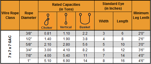
Specific to polyester round slings, it varies among manufacturers, but usually, they recommend minimum hardware diameters to protect the inner core yarns. The illustration above provides an example of minimum shackle size requirements when using round slings. Bear in mind that round slings are more negatively affected by users bunching up the sling and not allowing the yarns to spread out properly and disperse the load when in a choker configuration.
Using choker hitches may save headroom; however, even following manufacturer-specified hardware diameter, the sling’s rated capacity reduces to 75% of the listed vertical rating. Failing to understand this relationship often results in overloading the sling.
While all slings lose capacity when they are bent beyond a certain point, basket hitch ratings are based on a minimum diameter and the capacity must be reduced when the sling’s D/d falls below the minimum D/d ratio. Keep in mind, a true basket is one in which the legs of the sling remain at a 90-degree vertical angle.
In the rental business, we often see rigging equipment damaged due to sling capacity reduction being ignored or miscalculated. Often, the equipment is damaged beyond repair, leading to unsafe rigging practices and additional repair or replacement costs for our customers. This is why it’s imperative to understand and abide by D/d Ratio specifications.
When a wire rope is bent around any sheave or other object there is a loss of strength due to this bending action. As the D/d ratio becomes smaller this loss of strength becomes greater and the rope becomes less efficient. This curve relates the efficiency of a rope diameter to different D/d ratios. This curve is based on static loads and applies to 6-strand class 6×19 and 6×37 wire rope.
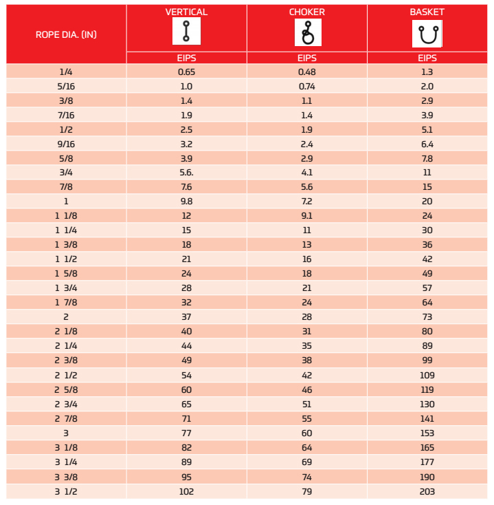
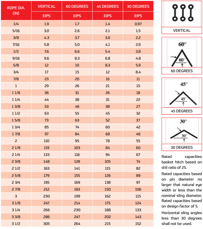
When a sling is used in a BASKET- or CHOKER HITCH with D/d ratios smaller than listed in the capacity tables, the rated capacities (or WLLs) must be decreased.
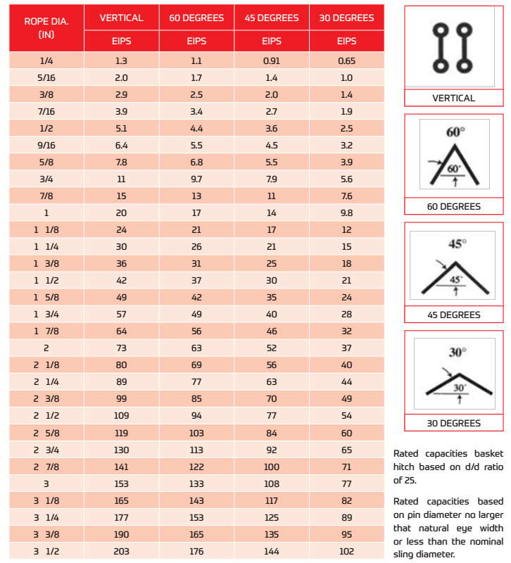
For example: The BASKET and CHOKER hitch capacities listed (in all Standards and Regulations) for 6-strand ropes are based on a minimum D/d ratio of 25:1.
An object you place into a 1" diameter 6-strand wire rope sling using a basket- or choker hitch must have a minimum diameter of 25". If the object is smaller than the listed 25:1 D/d ratio the capacity (or WLL) must be decreased. Table A) illustrates the percentage of decrease to be expected.
If the object lifted with a 6-strand wire rope sling in a basket hitch is at least 25 x larger than the sling diameter (D/d 25:1) the basket capacity need not to be adjusted.
It is better to use a larger shackle or a Wide Body shackle type. If the shackle or object has at least 5x the sling diameter (D/d 5:1) the basket sling capacity must still be reduced by about 25%.
Load Hooks must have sufficient thickness to ensure proper sling D/d ratio, particularly when using slings in an inverted basket hitch; that is the sling BODY is placed into the hook and the sling EYES are facing downwards.
Endless (or Grommet) slings DO NOT HAVE A LOOP which has double the strength of the sling body. Prior to EVERY lift, YOU, the user, has to determine if the D/d ratio is equal or higher than the ones listed in the capacity tables.
Wire rope and chain are the important part of the hoist which are closely bound up with the safe work load, now let’s talk about how to calculate the SWL of ropes and chains.
Sticking on national standards, DQCRANES has passed ISO9001 international quality system certification, ISO14004 environment management system certification, OHSA18001 and European CE Certifications which comprehensively promotes overall management level and makes DQCRANES known and welcomed by international customers.

With nearly 4,000 employees worldwide, WireCo WorldGroup is a great place for you to build a rewarding career. Our professionals enjoy the opportunities of a global manufacturing and distribution leader as well as a culture of open communication, professional growth, and friendly camaraderie that fosters innovation and problem solving.

The end point in a wire rope sling’s useful service life is prior to the failure of the sling. It must be removed from service when normal wear or accidental damage weakens the sling to the degree that an adequate factor of safety no longer exists.
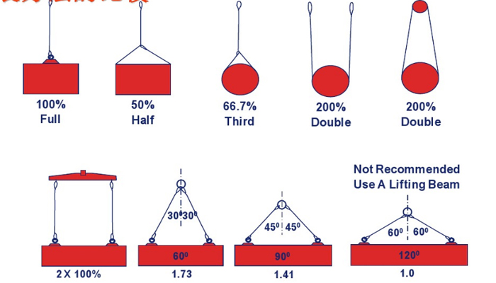
The term “Breaking Strength” is never used with reference to slings. Slings have a “Rated Capacity” that is determined by the manufacturer. A sling should never be used to lift a load that is greater than the published “Rated Capacity” for the particular sling and for the type of hitch being used. The design factor used in the calculation of a sling’s Rated Capacity compensates for normal dynamic loading and builds useful life into the sling.
Selection of a sling to lift a load is based on selecting a sling with a Rated Capacity at least equal to the weight of the load. The sling must also be proper to allow the user to select a hitch that will conform to the shape of the load and keep it under control during the lift, The use of multiple leg slings is not recommended when the angle between any leg and the vertical is greater than 450• In any case when lifting headroom is restricted and a larger leg angle is necessary, care must be exercised in selecting a sling with a proper Rated Capacity at the leg angle which will be used. A visual inspection of the sling must be conducted before each lift to make sure the sling is in new or near new condition. A manufacturer’s Rated Capacity applies only to an undamaged sling.
In any cable or wire rope application, stretch may be a concern. There are two forms of stretch in cable and wire rope: Structural Stretch and Elastic Stretch.
Structural stretch is the lengthening of the lay in the construction of cable and wire rope as the individual wires adjust under load. Structural stretch in Loos and Company products is less than 1% of the total cable length. This form of stretch can be completely removed by applying a cable or wire rope prestretching operation prior to shipment.
Elastic stretch is the actual physical elongation of the individual wires under load. The elastic stretch can be calculated by using the following formula*:

6x36 is a flexible general engineering wire rope readily available in galvanised, ungalvanised and marine grade stainless steel. The wire rope has an equal lay construction (warrington seale) and achieves a superior breaking load to the 6x19 construction range. The construction has been designed to give a flexible rope with a good fatigue life. A 6x36 wire rope is available with either FC (fibre core) or IWRC (independent wire rope core) and is used for a wide range of applications, examples of which are shown below:
6-1. INTRODUCTION. Section I of this chapter discusses blocks which are among the most important fittings used aboard ship on the deck, in the engine department, and in other operations. Section II covers elements of wire rope rigging which cargo handlers in a terminal service company must know. It details the care and use of wire rope, procedures for computing the safe working load and breaking strength, and inspection and handling. Section III covers marlinespike seamanship, which is a general term for handling and caring for fiber line and wire rope used aboard ship or in other marine operations.
b. Every tackle system contains a fixed block attached to some solid support and may have a traveling block attached to the load (see Figure 6-4). The single rope leaving the tackle system is called the fall line. Personnel apply the pulling force to the fall line which may be led through a leading block.
6-5. SIZES OF BLOCKS. Users can determine the size of blocks by measuring the length of the cheek in inches. Blocks are designated for use with a specific line size. Bending line over a sheave that is too small causes distortion and strain, resulting in the line wearing on the shell. Personnel can use line smaller than that designated for a sheave with no damage, but should never use line of a larger size.a. To determine the size wooden block to use with line of a known size, personnel may follow these formulas:
b. The size metal block to use with wire rope depends on the diameter of the sheave. The sheave is never less than 20 times the diameter of the wire. For example, personnel can determine the size block to use with 3/4-inch wire rope as follows:
6-7. TACKLE USES AND TYPES. A block with a line led over the sheave makes applying power by changing the direction of the pull easier. Used with line and another block, it becomes a tackle and increases the power applied on the hauling part. Tackles are designated according to their uses and the number of sheaves in the blocks that are used to make the tackle. The various types of tackle are rove with different size blocks and all have a limited lifting capacity depending on the number of sheaves, the size blocks and the size line used. The tackles are named for their use or from their makeup. The most commonly used tackles are explained below and illustrated in Figure 6-5.A single whip tackle consists of a single fixed block with a line passed over its sheave. This tackle has no mechanical advantage.
6-8. REEVING TACKLES. Personnel reeving tackles reeve each type differently. If a tackle is rove improperly, too much friction and possible binding of the falls can result when lifting or lowering a load, creating a safety hazard. It is important to use the proper method of reeving each type of tackle up to and including a threefold purchase.
6-10. FRICTION. A certain amount of the force applied to a tackle is lost through friction. Friction occurs in a tackle when lines rub against each other or against the frame or shell of the block, and pass over the sheaves. This loss in efficiency of the block and tackle (roughly 10 percent of the load per sheave) must be added to the weight being lifted to determine the total weight. For example, to determine the total weight of a load when lifting a load of 500 pounds with a twofold purchase, personnel use the following formula and compute:TW = W x (1 + Friction) or (1 + F)
6-11. BREAKING STRESS AND SAFE WORKING LOAD. The following paragraphs explain the procedures used to determine breaking stress and safe working loads for blocks and tackle loads. The symbols used in the formula for computations are as follows:W = Weight
* This table is computed in pounds for new line. For line that has been used these figures will decrease. Old line may have only 60 percent of the strength shown in pounds for a given size of line.b. To determine the SWL for a line of known size to be rove into a tackle, personnel should use one of the following formulas as appropriate, where "C" denotes circumference and "D" denotes diameter. The formulas for manila and nylon will give the SWL in pounds. The formulas for wire rope will be in tons.
c. If personnel are unsure which type of wire rope they are using, they must always use the formula for mild steel when figuring the SWL. This will ensure ultimate safety since the different strengths of wire rope cannot be identified visually.
6-12. CARE AND USE OF WIRE ROPE. Wire rope is made of steel except for its core which is likely to be fiber. The grades of wire rope in descending order of strength are: Extra improved plow, improved plow, plow, and mild plow steel. Of these four grades, the Army uses improved plow steel extensively and plow steel to a lesser extent. The manufacturer stamps the grade on the reel. Because the grade of wire rope is not visually apparent, it should always be considered as plow steel when in doubt.
6-13. MAKEUP OF WlRE ROPE. The basic unit of wire rope is the individual wire. Wires are laid together to form strands. The number of wires in a strand varies according to the purpose for which the rope is intended. Strands are laid around a core to form the wire rope itself. With preformed plow steel wire rope, the core may be hemp or polypropylene, a synthetic fiber. The core is a foundation to keep the wire rope round, to act as a shock absorber when the wire rope contracts under strain, and to serve as a reservoir for lubricant. Figure 6-7 shows a cross section of wire rope.
b. Strand Construction. In most wire rope used today, the wires and strands are preformed. Preforming means presetting wires in the strands into a permanent corkscrew form which they will have in the completed rope. As a result, preformed wire rope does not have the internal stresses found in nonpreformed wire rope, does not untwist as readily as nonpreformed wire rope, and is more flexible.
c. Types of Lay. Lay refers to the direction of winding of the wires in the strands and the strands in the rope. Both may be wound in the same direction or in opposite directions.(1) In regular lay, the strands and wires are wound in opposite directions. Most common is the right regular lay in which the strands are wound right and the wires wound left. This lay is used in marine operations.
6-15. MEASUREMENT. Whatever its grade, wire rope is usually measured by its diameter. Figure 6-8 shows the correct method of measuring the diameter of wire rope. To measure wire rope correctly, personnel should place it in the caliper so that the outermost points of the strands will be touching the jaws of the caliper.
6-16. SAFE WORKING LOAD AND BREAKING STRENGTH. The SWL and BS formulas are listed in the paragraphs below.a. Formulas for determining the SWL of several grades of wire rope have constants that are not to be confused with safety factors. For example, the formula for the SWL in STONs (2,000 pounds) for extra improved plow steel wire rope is diameter squared multiplied by 10, or SWL = D2 x 10. The formula to find the SWL of 1-inch, 6 x 19, extra improved plow steel wire rope is as follows: SWL = D2 x 10 = 1 x 1 x 10 = STONs.
b. A figure relatively constant in marine operations, especially for new wire rope, is the SF, which is 5. The SF is used with the SWL to find the BS.
6-17. INSPECTION OF WIRE ROPES. Wire ropes should be inspected frequently and replaced if frayed, kinked, worn, or corroded. The frequency of inspection depends on how often the rope is used. Wire rope used 1 or 2 hours a week requires less frequent inspection than one used 24 hours a day.a. Common causes of wire rope failures are as follows:Using rope of incorrect size, construction, or grade.
b. Carefully inspect weak points and points of greatest stress. Worn or weak spots show up as shiny, flat spots on the wires. If the outer wires have been reduced in diameter by one-half, the wire rope is unsafe.
c. Inspect broken wires, since they show where the greatest stress occurs. If individual wires are broken next to each other, unequal load distribution at this point will make the rope unsafe. Broken wires are called fishhooks. To determine the extent of damage to the wire rope, users can slide a finger along one strand of wire for one complete turn, equal to the length of one wire rope lay. Next, count the number of fishhooks. If six or more fishhooks are discovered, the wire rope is unsafe and should be replaced immediately.
6-18. HANDLING. There are different handling methods for wire rope. These methods are listed below.a. Kinking. When loose wire rope is handled, small loops frequently form in the slack portion of the rope. If personnel apply tension to the rope while these loops are in position, the loops will not straighten out but will form sharp kinks, resulting in unlaying of the rope. Personnel should straighten these loops out of the rope before applying a load. After a kink has formed in wire rope, it is impossible to remove it, and the strength of the rope is seriously damaged at the point where the kink occurs.
b. Unreeling. When removing wire rope from a reel or coil, personnel should be sure to rotate the reel or coil. If the reel is mounted, the wire rope may be unwound by holding the end and walking away from the reel. If a wire rope is in a small coil, personnel may stand the coil on end and roll it along the deck, barge, wharf, or ground. Remove any loops that may form, although rotating the reel or coil usually avoids causing loops to form.
c. Seizing. Personnel should seize (lash together) all wire rope before cutting it. If the ends of the rope are not properly secured, the original balance of tension is disturbed. Maximum use cannot be made on wire rope when some strands carry a greater load than others.
(2) There are three formulas for determining the number and length of seizings and the space between them. When a calculation results in a fraction, the next larger whole number is used. The following formulas are based on a 3/4-inch diameter wire rope.(a) The number of seizings required equals about three times the diameter of the rope. For example: 3 x 3/4 = 2 1/4 or 3 seizings. Because the rope will be cut, six seizings are required so that there will be three on each rope end after the cut.
d. Cutting. Wire rope may be cut with a wire rope cutter, a cold chisel, a hacksaw, bolt clippers, or an oxyacetylene cutting torch. When cutting wire rope, personnel should follow the procedures outlined below.(1) To seize the wire rope, insert it into the cutter with the blade between the two central seizings, close the locking device, then close the valve on the cutter. The handle should be pumped to build up enough pressure to force the blade through the rope.
(2) Use the bolt clippers on wire rope of fairly small diameter. Use the oxyacetylene torch on wire of any diameter. Cutting with the hacksaw and cold chisel is slower than cutting with the other tools and equipment.
e. Coiling. Personnel may need to take a length of wire rope from a reel and coil it down before using it. Small loops or twists will form if the wire rope is coiled in a direction opposite to the lay. To avoid loops, users should coil right lay wire rope clockwise and left lay wire rope counterclockwise. When a loop forms in the wire, they should put a back turn in as shown in Figure 6-10.
Figure 6-10. Putting a back turn in wire ropef. Size of Sheaves and Drums. When a wire is bent over a sheave or drum, two things happen: Each wire is bent to conform to the curvature, and the wires slide against each other lengthwise because the inside arc of the rope against the sheave or drum is shorter than the outside arc. The smaller the diameter of the sheave or drum, the greater the bending and sliding. Personnel should keep this bending and moving of wires to a minimum to reduce wear. The minimum recommended sheave and drum diameter is 20 times the diameter of the rope. For example, for 5/8-inch rope: 20 x 5/8 = 12 1/2-inch sheave. If a 12 1/2-inch sheave is not on hand, personnel should use the next larger size, never a smaller size.
g. Lubrication. Wire rope is lubricated as it is manufactured. The lubricant generally does not last throughout the life of the rope, which makes relubrication necessary. Crater "C" compound is recommended, but personnel may use oil on hand rather than delay lubrication. Crater "C" compound should be heated before it is put on the wire rope. Personnel should use a brush if possible to apply lubricant. If a brush is not available, they may use a sponge or cloth, but they should look out for fishhooks or broken wires.
h. Reversing Ends. It is sometimes advisable to reverse or cut back ends to get more service from wire rope. The wear and fatigue on a rope frequently is more severe at certain points than at others. Reversing distributes stronger parts of the rope to the points getting wear and fatigue. To reverse ends, personnel remove the drum end, put it in the attachment, and then fasten the end taken from the attachment to the drum. Cutting back the ends has a similar effect, but not as much change is involved. In reversing ends, personnel should cut off short lengths of both ends to remove the sections with the greatest local fatigue.
i. Storing. Wire rope should be coiled on a spool for storage. Its grade, size, and length are noted on a tag attached to the rope or spool. Wire rope should be stored in a dry place to reduce corrosion. Personnel should not store it with chemicals or where chemicals have been stored because chemicals and their fumes can attack the metal. Personnel should always clean and lubricate wire rope before storing it.
j. Cleaning. Personnel can remove most of the dirt or grit on a used wire rope by scraping or steaming. Rust should be removed at regular intervals by wire brushing. Personnel must clean the rope carefully before lubricating to remove foreign material and old lubricant from the valleys between the strands and from the spaces between the outer wires. This permits the newly applied lubricant to freely enter the rope.
6-19. CHARACTERISTICS AND FIBER LINE. To be able to work with fiber line, personnel must know its characteristics and properties. They must be able to handle and care for the line, and tie basic knots, bends, and hitches.a. Materials for Fiber Line. Fiber line is made of either vegetable or synthetic fibers. Vegetable fibers include manila, sisal, hemp, cotton, and flax. Synthetic fibers include nylon, Dacron, polyethylene, and polypropylene. The Army primarily uses nylon synthetic fiber line, so this manual covers only that synthetic fiber.(1) Manila is a strong fiber that comes from the leaf stems of the abaca plant, a part of the banana family. Varying in length from 4 to 15 feet in their natural state, the fibers have the length and quality which gives manila rope relatively high elasticity, strength, and resistance to wear and deterioration.
(3) Hemp is a tall plant that has useful fibers for making rope and cloth. It was used extensively before manila was introduced. Now hemp"s principal use is in fittings such as ratline and marline. Because hemp is absorbent, the fittings are tarred to make them more water-resistant.
Three-strand nylon line will stretch 30 to 35 percent under an average load or a load that does not exceed the safety factor for that size line. Three-strand nylon line will stretch 40 percent without being damaged and will draw back to its original length.e. Useful Formulas. To find the SWL and BS of the various lines, some useful formulas are listed below.(1) The manufacturer states the size and BS of its lines and if available, crew members should use the manufacturer"s figures for determining the strength of line. If this information is not available, personnel should use the following formula and constant for type line to compute the SWL and the BS: C2 x constant for type line = SWL (in pounds), where "C" denotes circumference in inches. Constants for type line are as follows:
6-23. WHIPPING LINE. Personnel must never cut a line or leave the end of a line dangling loose without a whipping to prevent it from unlaying. A line without whipping will unlay of its own accord. Whenever a line or hawser has to be cut, whippings should be put on first, on each side of the cut. To prevent fraying, a temporary or plain whipping can be put on with any type cordage, even rope yarn. Figure 6-12 shows one of the several methods that can be used for putting a temporary whipping on a line.
e. French Bowline. A French bowline is used as a sling for lifting an injured person. For this purpose one loop is used as a seat and the other loop is put around the body under the arms, with the knot drawn tight at the chest. Even an unconscious person can be hoisted safely in a properly secured French bowline, because the weight applied will keep the two loops tight so that the individual will not fall out. Personnel must not allow the loop under the person"s arms to catch on any projections. The French bowline may also be used if a person is working alone and needs both hands free. The two loops of the knot can be adjusted to the required size. Figure 6-18 shows the step-by-step procedure for tying the French bowline.
Figure 6-20. Clove hitchh. Stopper Hitch. A slight defect of a clove hitch is that it can slide along the cylindrical object to which it is tied. To guard against this, personnel should use a stopper hitch (commonly called a rolling hitch) which is illustrated in Figure 6-21. This figure shows fiber rope; with wire rope, personnel would use a small chain.
6-25. SPLICING THREE-STRAND FIBER LINE. Splicing is a method of permanently joining the ends of two lines or of bending a line back on itself to form a permanent loop or an eye. If two lines are to be spliced, strands on an end of each line are unlaid and interwoven with those of the standing part of the line. Small stuff can be spliced without a fid, which is a tapering length of hard wood used in splicing larger lines. A knife is used to cut off the ends of the strands.a. Short Splice. The short splice is as strong as the rope of which it is made. However, the short splice increases the diameter of the rope and can be used only where this increase in diameter will not affect operation. The splice is frequently used to repair damaged ropes or where two ropes of the same size are to be joined together permanently. Damaged parts of the rope are cut out and the sound sections are spliced. Personnel should follow these steps-(1) Untwist one end of each line five complete turns. Whip or tape each strand. Bring these strands tightly together as in Figure 6-22, view 1, so that each strand of one line alternates with a strand of the other line. Put a temporary whipping on the lines where they join to keep them from suddenly coming apart. Do this procedure with small lines until you are skilled enough to hold them together while you tuck.
6-26. PUTTING AN EYE IN WIRE ROPE. This paragraph discusses how to put both a temporary eye and a permanent eye in wire rope. A temporary eye can be put in wire rope by using wire rope clips or by using a field expedient known as a "hasty eye" or "Molly Hogan" splice. A liverpool splice is the accepted method for putting a permanent eye in the end of a wire rope. With the proper equipment, and a bit of practice, a liverpool splice can be put in wire rope in less than 15 minutes.a. Splicing Tools. With the exception of the wire cutters, Figure 6-24 shows the tools needed for splicing. The marlinespike is used for opening the strands in the standing part of the wire rope and for working the strands to be spliced into the standing part. The wire cutters are used for cutting the strands after the splice is complete. The hydraulic wire rope cutter is used to cut the length of wire rope that will be spliced. A thimble is used to keep the wires from moving and the rigger"s vise from crushing them when a soft eye is made. After the soft eye is spliced, the thimble is removed. When an eye is to have a thimble as a permanent part, the thimble is the size of the eye desired.
b. Temporary Eye. A temporary eye may be put in wire by using wire rope clips. Figure 6-25 shows the correct way of using these clips. As the illustration shows, a wire rope clip consists of two parts: the U-bolt and the roddle, the part into which the U-bolt is inserted. Personnel should always put the U-bolt over the bitter end and the roddle on the standing part. This procedure protects the live or stress-bearing end of the rope against crushing. The roddle protects the rope and, therefore, should always be placed against the live end.(1) To obtain maximum strength from the temporary eye splice, use the correct size and number of wire clips, and the correct spacing between them. Size is stamped on the roddle between the two holes. Personnel may use the following formula to determine the number of clips: 3 x diameter of wire rope + 1 = number of clips. For example, the number of clips needed for l-inch wire rope is: 3 x 1 + 1 = 4. To determine the correct space between clips, multiply the diameter of the rope by six. For example, the space between clips to be put on 1-inch rope is: 6 x 1 = 6 inches. Measure the space from the center of one clip to the center of the next one. If the calculation for either the number or the space results in a fraction, round off to the next higher whole number.
(2) The improved type of wire rope clips shown in Figure 6-26 has a few advantages over the older type. Both halves are identical and provide a bearing surface for both parts of the rope. Thus, it cannot be put on wrong and does not distort the wire. It also allows a full swing with a wrench.
c. Hasty Eye (Molly Hogan) Splice. Occasionally it becomes necessary to construct a field expedient, called the hasty eye or Molly Hogan splice. This splice can be quickly made, but it is limited to about 70 percent of the strength of the wire rope. It should not be used to lift heavy loads. This splice can be used only when working with preformed wire rope. To make a hasty eye splice, personnel should follow these steps:(1) Using a marlinespike, screwdriver, or, if necessary, a nail, separate the wire rope into two three-strand sections. These sections should be unlaid four times the diameter of the desired eye. If you want a l-foot diameter eye, unlay the sections back 4 feet.
d. Liverpool Splice. The liverpool splice is the easiest and most common of the wire splices to make. It is the primary splice used when a permanent eye is required. Personnel should follow these instructions:(1) Forming the eye. To find the distance, the strands should be unlaid for an eye splice; then, multiply the diameter of the wire by 36 inches. (For example, to determine the distance of a 5/8-inch wire rope: multiply 5/8 x 36/1 = 180/8 = 22 1/2 or 23 inches.) Measure off that distance on the wire rope and put a seizing at that point. Cut the end seizing and carefully unlay the strands. Whip the ends of each strand with either sail twine or friction tape. Form the desired size eye and put the eye in the rigger"s vise with the unlaid strands to your right as you face the vise. Stretch out the standing part of the wire, clamp and lash it and you are ready to start.
NOTE: When splicing wire, always insert the marlinespike against the lay of the wire, and make sure not to shove it through the core. The core must be on the left-hand side of the spike.(2) Making the first tuck of strands one, two, and three. In the liverpool splice, the first strand goes under three strands, the second strand goes in the same opening but only under two strands, and the third strand goes in the same opening but only under one strand. All of the strands go in at the same point, but come out at different places (Figure 6-27). At this time, run the spike behind the three strands under which the first three are tucked, but above the first three tucked strands. Holding the marlinespike at a 90-degree angle to the standing part, turn the spike counterclockwise about one fourth of a turn and insert the core through the standing part. This is called "dipping the core." Make sure that the core is inserted under the marlinespike. Pull the core down and run it down into the splice.
(5) Tucking strands one, two, and three. To finish the splice, tuck number three, two, and one. Each is tucked three times in a row, ending up with an overall total of four tucks for each. To avoid kinking the strands on the last tucks, insert the spike and run it up the wire. Follow the spike up with the strand, shove it under the spike, and pull taut. Keeping a strain on the strand, work the spike and strand back around and down together. Hold the strand there and work the spike back up the wire. Follow up with the strand and take the last tuck. Work the strand back down and hold it there. Before pulling out the spike, run it back up until the strands of the standing wire bind the working strand in place. Make the second and third tucks with the remaining strands in the same way.
(6) Completing a splice. Remove the wire from the vise, use a hammer to pound the splice into shape, and cut off the ends of the tucking strands close to the splice.


 8613371530291