
wire rope clip spacing formula manufacturer
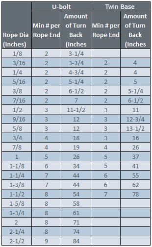
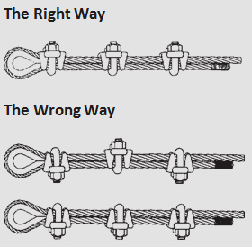
U-bolt Clips.There is only one correct method for attaching U-bolt clips to wire rope ends, as shown in TheRightWayimage below. The base of the clip bears on the live end of the rope; the “U” of the bolt bears on the dead end.
Compare this with the incorrect methods. Five of the six clips shown are incorrectly attached—only the center clip in the top view is correct. When the “U” of the clip bears on the live end of the rope, there is a possibility of the rope being cut or kinked, with subsequent failure.

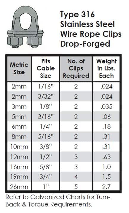
Wire Rope Clip a.k.a Bulldog Clip or U-Bolt Clip which used to clamp the loose end of wire rope by looping the wire rope back and form eye to create a bearing point. The termination efficiency of forged wire rope clip shall be 80%.
According to EN 13411-5, grip secured eye termination wire rope is only suitable in suspending static load and single use lifting operation (one time use lifting operation with proper safetyfactor consideration). To use with spiral rope or use it in general lifting sling make is not recommended.
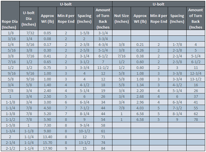
Proper secure of wire rope clip, the distance, d between wire rope clip and the distance of wire rope clip to tail have to be at least 1.5 times and not more than 3 times of the wire rope clip base width. Collar nut shall be secured with proper torque value according to size of the wire rope clip to prevent crushing the wire rope if the torque value is too large or wire rope slip over uf the torque value is below the proper or recommended collar nut pre-load value.
The number of malleable wire rope clip used in securing eye termination shall be one more than the forged wire rope clip used in same size of wire rope.
Proof load value of Grip Secured eye termination shall is 20% of the wire rope Minimum Breaking Strength, the collar nut needs to be re-torque to proper value after the proof load testing.
U-bolt on the bitter (dead) end, not on the standing part of the wire rope. If clips are attached incorrectly, the standing part (live end) of the wire rope will be distorted or have mashed spots. A rule of thumb when attaching a wire rope is to NEVER saddle a dead horse.
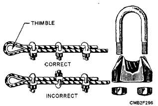
Another type of wire rope clip is the twin-base clip, often referred to as the universal or two clamp (fig. 6-56). Both parts of this clip are shaped to fit the wire rope, so the clip cannot be attached incorrectly. The twin-base clip allows for a clear 360-degree swing with the wrench when the nuts are being tightened.
THIMBLE. - When an eye is made in a wire rope, a metal fitting, called a thimble, is placed in the eye, as shown in figure 6-55. The thimble protects the eye against wear. Wire rope eyes with thimbles and wire rope clips can hold approximately 80 percent of the wire rope strength.
After the eye made with clips has been strained, the nuts on the clips must be re-tightened. Checks should be made now and then for tightness or the clips will cause damage to the rope.
SWAGED CONNECTIONS. - Swaging makes an efficient and permanent attachment for wire rope, as shown in figure 6-57. A swaged connection is made by compressing a steel sleeve over the rope by using a hydraulic press. When the connection is made properly, it provides 100 percent capacity of the wire rope.
Careful inspection of the wires leading into these connections is important because of the pressure put upon the wires in this section. If one broken wire is found at the swaged connection or a crack in the swage, replace the fitting.
HOOKS AND SHACKLES. - Hooks and shackles are handy for hauling or lifting loads without tying them directly to the object with line, wire rope, or chain. They can be attached to wire rope, fiber line, blocks, or chains. Shackles should be used for loads too heavy for hooks to handle.

(a) Factor of Safety. All rope to be used for regular hoisting shall be wire rope providing a factor of safety not less than five to one for material hoist and ten to one for personnel hoist when new, which shall be calculated by dividing the breaking strength of the wire rope as given in the manufacturer"s published tables, by the total load to be hoisted including the total weight of the wire rope in the shaft when fully let out, plus a proper allowance for impact and acceleration.
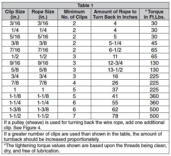
(b) Wire Rope Fastenings. Every wire rope used for hoisting shall be securely fastened at both ends and when in use shall not be fully unwound; at least three full turns shall remain on the drum so as to protect the end fastening at drum from overload. The wire rope end at the cage, skip or bucket shall be securely fastened by a properly made tapered socket joint, by an eye in the wire rope made with an oval thimble and wire rope clips, or by another method acceptable to the Division for this or similar service. If the wire rope clip method is used, the spacing and number used shall be as shown in Table - 1 for U-Bolts and in Table - 2 for Fist-Grip clips based upon using RRL or RLL wire rope, 6 x 19 or 6 x 37 Class, FC or IWRC; IPS or XIP. If Seale construction or similar large outer wire type construction in the 6 x 19 Class is to be used for sizes 1 inch and larger, add one additional clip. If a pulley (sheave) is used for turning back the wire rope, add one additional clip.
The number of clips shown also applies to rotation-resistant RRL wire rope, 8 x 19 Class, IPS, XIP, sizes 1-1/2 inch and smaller; and to rotation-resistant RRL wire rope, 19 x 7 Class, IPS, XIP (sizes 1-3/4 inch and smaller for U-Bolts and size 1-1/2 inch and smaller for Fist Grips).
(d) Splicing. Spliced wire rope shall not be used, except that the end may be attached to the load by the thimble and/or clip method, as provided in subsection (b) of this section.
(1) A safety hook, shackle or other means providing closed design protection shall form the attachment between rope and a bucket, cage, skip or load. The attachment shall be made so that the force of the hoist pull, vibration, misalignment, release of lift force, or impact will not disengage the connection. Moused or open-throat hooks with light safety latches do not meet this requirement.
(2) All wire rope fittings and connections shall be in accordance with the manufacturers" specifications and compatible with the type of wire rope used.
(g) Drum Flanges. The drum of any hoist used for hoisting shall have flanges which extend at least 2 inches radially beyond the last layer of rope when all the rope is coiled on the drum.

(3) When U-bolt cable clips are used to form eyes, Table 3: U-bolt Cable Clips to Form Eyes must be used to determine the number and spacing of clips.
(a) For eye splices, the U-bolt wire rope clip must be attached so that the U section is in contact with the dead or short end of the rope (see Figure 3: Eyes Formed with U-bolt Cable Clips);
(b) U-bolt cable clips must be spaced at least six rope diameters apart to obtain the maximum holding power. Nuts must be tightened evenly and tightened again after application of the first sustained load. After the rope has been used and is under tension, the clips must be tightened again to take up any looseness caused by the tension reducing the rope diameter;
Original equipment wire rope and replacement wire rope must be selected and installed in accordance with the requirements of this section. Selection of replacement wire rope must be in accordance with the recommendations of the wire rope manufacturer, the equipment manufacturer, or a qualified person.
Wire rope design criteria: Wire rope (other than rotation resistant rope) must comply with either Option (1) or Option (2) of this section, as follows:
Option (1). Wire rope must comply with section 5-1.7.1 of ASME B30.5-2004 (incorporated by reference, see § 1926.6) except that section"s paragraph (c) must not apply.
Option (2). Wire rope must be designed to have, in relation to the equipment"s rated capacity, a sufficient minimum breaking force and design factor so that compliance with the applicable inspection provisions in § 1926.1413 will be an effective means of preventing sudden rope failure.
Type I rotation resistant wire rope ("Type I"). Type I rotation resistant rope is stranded rope constructed to have little or no tendency to rotate or, if guided, transmits little or no torque. It has at least 15 outer strands and comprises an assembly of at least three layers of strands laid helically over a center in two operations. The direction of lay of the outer strands is opposite to that of the underlying layer.
Type II rotation resistant wire rope ("Type II"). Type II rotation resistant rope is stranded rope constructed to have significant resistance to rotation. It has at least 10 outer strands and comprises an assembly of two or more layers of strands laid helically over a center in two or three operations. The direction of lay of the outer strands is opposite to that of the underlying layer.
Type III rotation resistant wire rope ("Type III"). Type III rotation resistant rope is stranded rope constructed to have limited resistance to rotation. It has no more than nine outer strands, and comprises an assembly of two layers of strands laid helically over a center in two operations. The direction of lay of the outer strands is opposite to that of the underlying layer.
Type I must have an operating design factor of no less than 5, except where the wire rope manufacturer and the equipment manufacturer approves the design factor, in writing.
A qualified person must inspect the rope in accordance with § 1926.1413(a). The rope must be used only if the qualified person determines that there are no deficiencies constituting a hazard. In making this determination, more than one broken wire in any one rope lay must be considered a hazard.
Each lift made under § 1926.1414(e)(3) must be recorded in the monthly and annual inspection documents. Such prior uses must be considered by the qualified person in determining whether to use the rope again.
Rotation resistant ropes may be used as boom hoist reeving when load hoists are used as boom hoists for attachments such as luffing attachments or boom and mast attachment systems. Under these conditions, all of the following requirements must be met:
The requirements in ASME B30.5-2004 sections 5-1.3.2(a), (a)(2) through (a)(4), (b) and (d) (incorporated by reference, see § 1926.6) except that the minimum pitch diameter for sheaves used in multiple rope reeving is 18 times the nominal diameter of the rope used (instead of the value of 16 specified in section 5-1.3.2(d)).
The operating design factor for these ropes must be the total minimum breaking force of all parts of rope in the system divided by the load imposed on the rope system when supporting the static weights of the structure and the load within the equipment"s rated capacity.
Wire rope clips used in conjunction with wedge sockets must be attached to the unloaded dead end of the rope only, except that the use of devices specifically designed for dead-ending rope in a wedge socket is permitted.
Prior to cutting a wire rope, seizings must be placed on each side of the point to be cut. The length and number of seizings must be in accordance with the wire rope manufacturer"s instructions.

Wire rope is often used in slings because of its strength, durability, abrasion resistance and ability to conform to the shape of the loads on which it is used. In addition, wire rope slings are able to lift hot materials.
Wire rope used in slings can be made of ropes with either Independent Wire Rope Core (IWRC) or a fiber-core. It should be noted that a sling manufactured with a fiber-core is usually more flexible but is less resistant to environmental damage. Conversely, a core that is made of a wire rope strand tends to have greater strength and is more resistant to heat damage.
Wire rope may be manufactured using different rope lays. The lay of a wire rope describes the direction the wires and strands are twisted during the construction of the rope. Most wire rope is right lay, regular lay. This type of rope has the widest range of applications. Wire rope slings may be made of other wire rope lays at the recommendation of the sling manufacturer or a qualified person.
Wire rope slings are made from various grades of wire rope, but the most common grades in use are Extra Improved Plow Steel (EIPS) and Extra Extra Improved Plow Steel (EEIPS). These wire ropes are manufactured and tested in accordance with ASTM guidelines. If other grades of wire rope are used, use them in accordance with the manufacturer"s recommendations and guidance.
When selecting a wire rope sling to give the best service, consider four characteristics: strength, ability to bend without distortion, ability to withstand abrasive wear, and ability to withstand abuse.
Rated loads (capacities) for single-leg vertical, choker, basket hitches, and two-, three-, and four-leg bridle slings for specific grades of wire rope slings are as shown in Tables 7 through 15.
Ensure that slings made of rope with 6×19 and 6x37 classifications and cable slings have a minimum clear length of rope 10 times the component rope diameter between splices, sleeves, or end fittings unless approved by a qualified person,
Ensure that braided slings have a minimum clear length of rope 40 times the component rope diameter between the loops or end fittings unless approved by a qualified person,
Do not use wire rope clips to fabricate wire rope slings, except where the application precludes the use of prefabricated slings and where the sling is designed for the specific application by a qualified person,
Ensure that wire rope slings have suitable characteristics for the type of load, hitch, and environment in which they will be used and that they are not used with loads in excess of the rated load capacities described in the appropriate tables. When D/d ratios (Fig. 4) are smaller than those listed in the tables, consult the sling manufacturer. Follow other safe operating practices, including:
When D/d ratios (see Fig. 6) smaller than those cited in the tables are necessary, ensure that the rated load of the sling is decreased. Consult the sling manufacturer for specific data or refer to the WRTB (Wire Rope Technical Board) Wire Rope Sling Users Manual, and
Before initial use, ensure that all new swaged-socket, poured-socket, turnback-eye, mechanical joint grommets, and endless wire rope slings are proof tested by the sling manufacturer or a qualified person.
Permanently remove from service fiber-core wire rope slings of any grade if they are exposed to temperatures in excess of 180 degrees F (82 degrees C).
Follow the recommendations of the sling manufacturer when you use metallic-core wire rope slings of any grade at temperatures above 400 degrees F (204 degrees C) or below minus 40 degrees F (minus 40 degrees C).
Northern Strands, safety is one of our top priorities. Therefore, knowing how to properly clip wire rope using Crosby clips is very important in order to practice safe rigging. Keep in mind that the wire rope clip must be the correct size for the diameter of the rope that is being used and that there is a specific number of clips that are required according to rope size.
A quick rule of thumb for proper clip installation is, "Never Saddle a Dead Horse". This refers to the live end of the wire rope that rests in the saddle of the forged wire clip and the U-bolt that is placed on the dead end of the wire rope.
Efficiency ratings for wire rope end terminations are based upon the minimum breaking force of wire rope. The efficiency rating of a properly prepared loop or thimble-eye termination for clip sizes 1/8” through 7/8” is 80%, and for sizes 1” through 3-1/2” is 90%.
The number of clips shown (see Table 1) is based upon using RRL or RLL wire rope, 6 x 19 or 6 x 36 Class, FC or IWRC; IPS or XIP, XXIP. If Seale construction or similar large outer wire type construction in the 6 x 19 Class is to be used for sizes 1 inch and larger, add one additional clip. If a pulley (sheave) is used for turning back the wire rope, add one additional clip.
The number of clips shown also applies to rotation-resistant RRL wire rope, 8 x 19 Class, IPS, XIP, XXIP sizes 1-1/2 inch and smaller; and to rotation-resistant RRL wire rope, 19 x 7 Class, IPS, XIP, XXIP sizes 1-3/4 inch and smaller. For other classes of wire rope not mentioned above, we recommend contacting Crosby Engineering to ensure the desired efficiency rating.
For elevator, personnel hoist, and scaffold applications, refer to ANSI A17.1 and ANSI A10.4. These standards do not recommend U-Bolt style wire rope clip terminations. The style wire rope termination used for any application is the obligation of the user.For OSHA (Construction) applications, see OSHA 1926.251.
1. Refer to Table 1 in following these instructions. Turn back specified amount of rope from thimble or loop. Apply first clip one base width from dead end of rope. Apply U-Bolt over dead end of wire rope – live end rests in saddle (Never saddle a dead horse!). Use torque wrench to tighten nuts evenly, alternate from one nut to the other until reaching the recommended torque. (See Figure 1)
Wire rope clips are widely used for making end terminations. Clips are available in two basic designs; the U-Bolt and fist grip. The efficiency of both types is the same.
When using U-Bolt clips, extreme care must be exercised to make certain that they are attached correctly; Incorrect installation can reduce the working load limit by 40%. Below are general guidelines for installing wire rope clips.
The saddle shall be placed on the live end of the wire rope, with the U-bolt on the dead-end side—Remember the well-known saying: “Never saddle a dead horse.” Use at least two or three wire rope clips to secure the ends properly to the length of the rope, and tighten nuts evenly one by one until reaching the recommended torque.
Step 1. Turn back a specified amount of rope from the thimble or loop. The first clip must be placed one bridge width from the turned back rope tailor dead end of the rope, Apply U-Bolt over dead end of wire rope – live end rests in the saddle (Never saddle a dead horse!) Tighten nuts evenly, alternate from one nut to the other until reaching the recommended torque.
Step 2. When more than two clips are required, apply the second clip as near the loop or thimble as possible, tighten the nuts firmly but not yet to the specified torque.
Step 3. When three or more clips are required, space additional clips equally between the first two – take up rope slack – tighten nuts on each U-Bolt evenly, alternating from one nut to the other until reaching recommended torque.
In accordance with good rigging and maintenance practices, the wire rope end termination should be inspected periodically for wear, abuse, and general adequacy. Periodically re-tightening of the nuts must be done at 10.000 cycles (heavy usage), 20.000 e.g. every 3 months, 6 months, annually.
Malleable clips are to be used for making eye termination assemblies only with the right regular lay wire rope and only for light-duty uses with small applied loads, such as handrails, fencing, guard rails, etc.
If you have any wire rope clips questions, you can contact us by email at info@hilifting.com. We will be glad to share with you more useful information.


 8613371530291