
wire rope crash barrier pricelist
Established in2014, V. A. Engg. & Infrais a leading organization affianced in the area of manufacturing a broad plethora of Cats Eyes Road Marking Stud, Guard Rails and Crash Barrier. In their development process, we assure that only top notch basic material is used by our professionals along with ultra-modern tools and machinery. Besides this, we check these on a variety of grounds before finally shipping them at the destination of our customers. Together with this, our offered facility of customization in order to attain high level of customer satisfaction has earned us huge number of satisfied customers.

We,Om Wire & Wire Products Industries, are one of the recognized manufacturer of the wide-spread range of all kinds of Metal Beam Crash Barrier, Octagonal Poles, High Mast Poles, Swag Poles, Conical Poles, Road Signage etc. We continuously strive to better our range and therefore, we lay great emphasis on quality and ensure that we offer an exclusive range to our customers so that they are proud to be associated with us.
BRIFEN Wire Rope Safety Barrier has been fully crash tested and evaluated according to the specifications for Test Level 3 (TL3) of the AASHTO Manual for Assessing Safety Hardware (MASH).
Under NCHRP-350, it was common for proprietors to crash test short installation lengths and set the cable tensions to their highest value producing low deflection results.
Tools required for the installation of BRIFEN Wire Rope Fence include auger or excavating machinery, concrete trowel, wire rope grips and swaging machine.
We manufacture and supply our clients a broad array of Crash Barriers. Designed for installation at the roads, these are used to keep away the motorists from the edges. These are designed and manufactured using pristine quality basic materials and sophisticated techniques in tandem with industry standards. Also, our quality inspectors test all types of crash barriers / safety barriers on set quality parameters to assure their durability and rugged design. We offer these road safety equipment to the clients in different lengths, thicknesses and designs at nominal prices.

Safence is a product from Blue Systems which we have developed together with the Danish company Brdr. Markussens Metalvarefabrik (BMM). The wire rope fences are designed to meet the requirements for road safety barriers according to NCHRP 350-TL4 and the new European CEN standards.
Within the European standards organisation CEN, standards have been worked out as to how impact testing of safety barriers is to be carried out. These impact tests for road safety barriers are described in prEN 1317, Road Restraint Systems. The CEN standards place functional demands on road barriers from the viewpoint of road safety, and establish different containment levels for testing road safety barriers. The traffic environment where they are to be installed determines which containment level should be used and which working width can be allowed. Also included in the CEN standards is the demand that there should be minimal risk of personal injury in a collision with the barrier (Impact severity level).
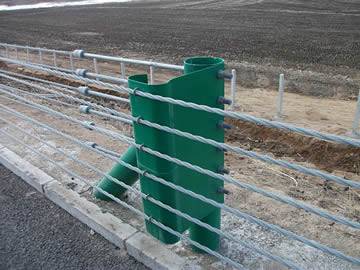
The repair of a wire rope fence is quick and easy due to the slotted post holes whereby posts are easily removed and replaced. It is important that repair work on the fence can be done easily and quickly without any loss of quality. In order to ensure the quality, function, length of life and standards of service for our products, we offer training to the service personnel concerned on each stretch of highway where our fence has been installed.
1. This section of the specification covers the supply, installation and foundation requirements of the following representative types of vehicle crash barriers. The definition of each type of barrier is given in the relevant section of the specification.
1. The vehicle crash barriers shall present a continuous smooth face to an impacting vehicle so that the vehicle is redirected without turning on its side or rolling over to a course that is nearly parallel to the barrier face and with a lateral deceleration which is tolerable to the vehicle occupant. The vehicle shall be redirected without rotation about either its horizontal axis (spinning out) or vertical axis (overturning) and the rate of lateral deceleration shall be such as to cause minimum risk of injury to the passengers.
2. The vehicle shall be directed so that no part of the vehicle crosses the line parallel with and 4 m from the original alignment of the traffic face of the fence or barrier within a distance of 10 m from the last point of initial impact in the direction of the adjacent traffic flow.
3. On impact the safety fence or barrier shall contain and redirect a vehicle of a certain mass travelling at a certain velocity at an angle of incidence of 20 degrees to the fence or barrier.
5. All the components of a vehicle crash barrier shall be designed to achieve a serviceable life of not less than 20 years except for the use of temporary concrete barriers where the nominal service life shall not be less than 10 years.
1. The Contractor shall submit details of previous installations of the vehicle crash barrier over a 10-year period, indicating the system, its location and the type of highway.
2. For the particular crash barrier system proposed, the Contractor shall submit a detailed report giving the results of vehicle impact tests, and may include photographs and video recordings. The report shall be from an internationally recognised laboratory approved by the Engineer. The report shall describe in detail the arrangements for the test including vehicle weight, speed, impact area, full details of the test vehicle guidance and measuring systems and speed measurements. The report shall include photographs showing the results of the test. The report shall give full details of the actual vehicle speed, approach angle, vehicle interaction and fence movement of vehicle and roll, yawl and pitch of the vehicle movement after exit from safety fence. The report shall include details of the safety fence damage and the vehicle damage.
3. Crash cushions and terminals. The Contractor shall make a detailed technical submission that will include drawings indicating the layout for the system at different locations. The Contractor shall also submit design calculations for the system for head on impact and side impact. These calculations shall indicate the reduction in G force or all vehicles of specified weight and speed. The submission shall contain the precise specification of the individual elements of the system, installation procedures, fixing details and fully dimensioned scale layout drawings. The Contractor shall submit reports from the highway authority where the particular barrier system has been used showing details of vehicle collisions and the results of such collisions.
6. The Contractor shall submit calculations showing the required size and details of the lifting eyes for permanent and temporary concrete barriers for the designated barrier details.
1. Vehicle crash barriers shall have been tested by an approved Testing establishment such as the UK Transport and Research Laboratory. The Engineer shall decide what is an approved Testing establishment.
2. The manufacturer shall operate an approved quality assurance system complying with ISO 9002 for the fabrication and supply of components used in the vehicle safety barriers. Only components complying with the manufacturer’s specifications may be used.
4. Crash cushion and terminal systems shall have been satisfactory tested following the procedures set down in the US Department of Transportation Research Report NCHRP, No. 230. The installation of the system shall be supervised by a representative of the manufacturer with a minimum of five years of experience in the use of the system.
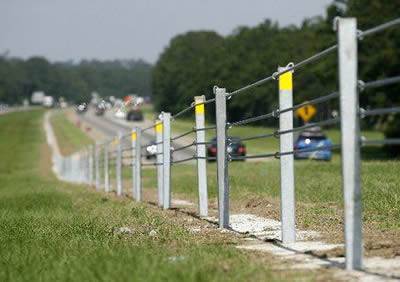
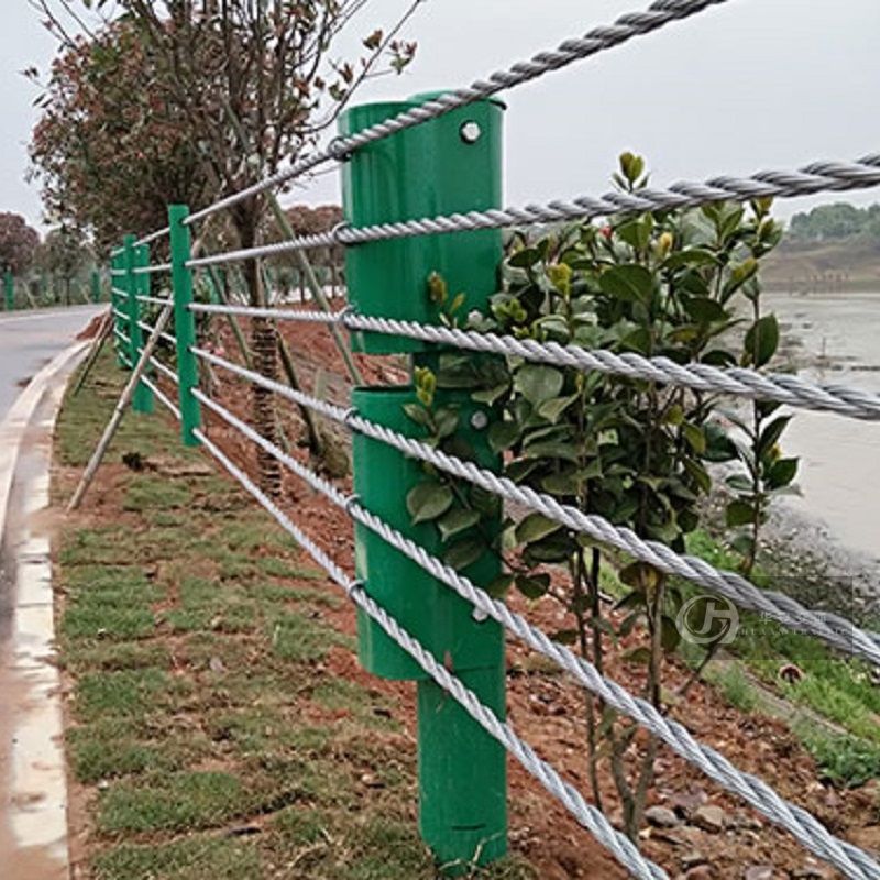
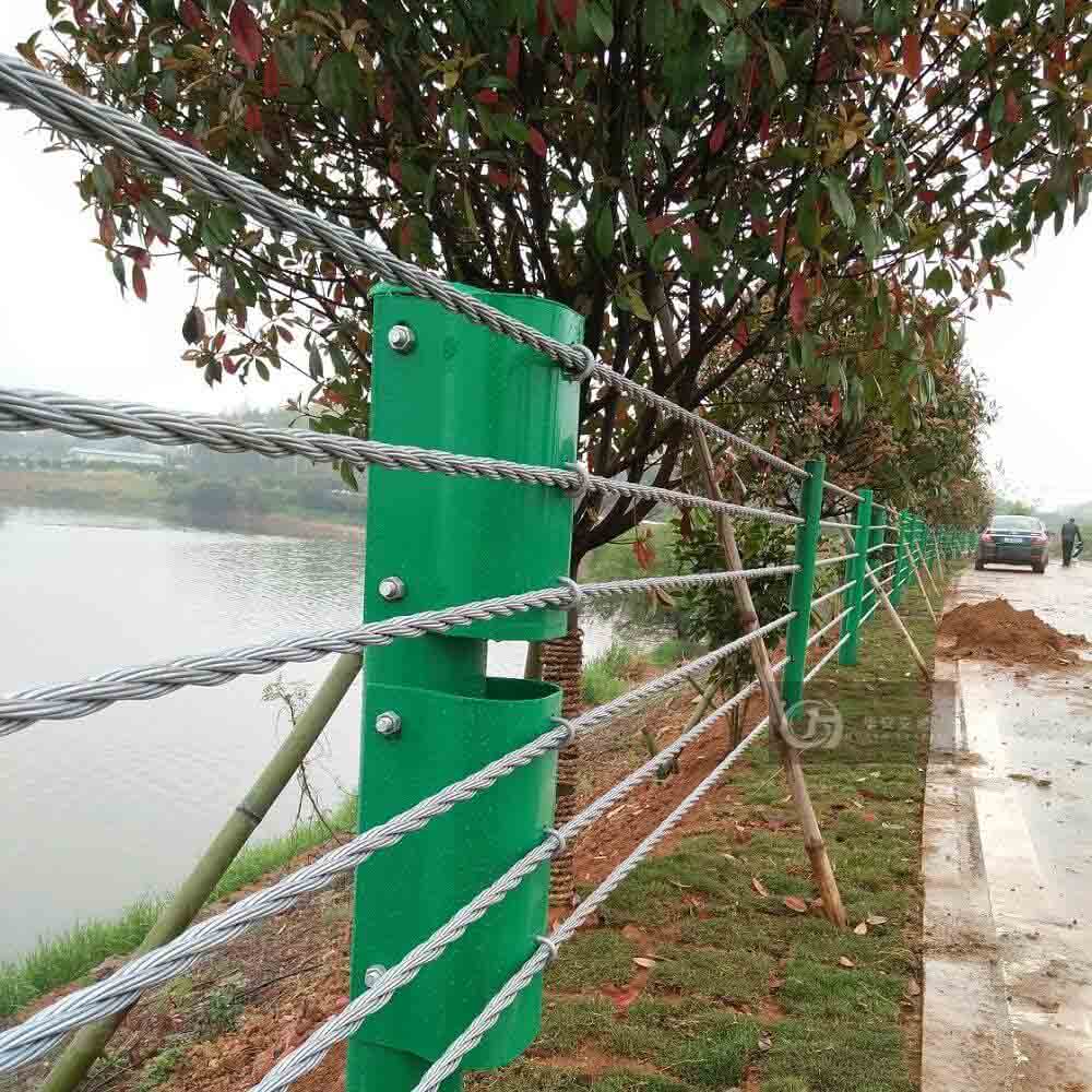
1. Steel wire rope safety fence barriers shall be supplied and installed in accordance with the designated dimensions and details shown on the contract drawings. The post details, spacing, anchorage, size shapes and general layout shall be as per the details shown on the contract drawings.
2. Wire rope barriers shall consist of either two or four, tensioned, galvanised, steel-wire ropes. The type of system to be specified shall be as shown on the contract drawings.
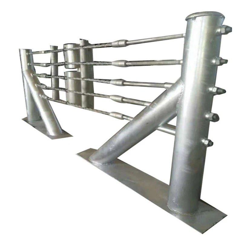
3. Four wire rope barriers shall consist of two upper ropes located in a slot at the top of the steel posts and two lower ropes interwoven along the fence between each pair of ropes. The ropes shall be joined and tensioned by means of screws at the designated intervals.
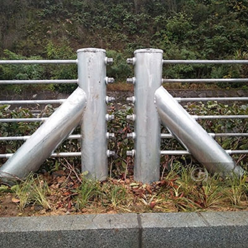
4. The ends of the ropes shall be attached to anchor blocks and embedded in the ground. Steel posts may be located in the ground either as driven posts or in concrete footings. In the case of any obstruction, the Contractor shall propose an alternative steel post, surface mounted to the equivalent of strain. Steel posts shall be removable and replaceable.
2. The rope shall be 19 mm diameter, 3 x 7 (fill) galvanised wire rope generally to BS 302: Part 1 with a minimum breaking force of 173.6 kN. All wire used in the rope shall be to BS EN 10264 galvanised normal duty. Various galvanised wire finishes may be used by agreement with the Engineer.
3. The rope shall be prestressed by applying a cyclic loading until all initial extension has been removed. After prestressing the rope will exhibit a minimum modulus of elasticity of 8300 kg/mm2 based on an area of 283 mm2.
5. The fittings shall be attached to the rope whose length measured over the extreme ends of the threaded portion of the fittings shall be 153.35 m, -0/+25 mm. Other special lengths of rope with identical construction may be detailed as necessary for specific applications.
7. A test will be carried out to destruction on a threaded terminal test piece consisting of a terminal and a length of rope such that the minimum test length is 600 mm. This assembly shall have a minimum breaking force of 164.6 kN.
1. Tail ropes shall be short lengths of rope fitted with threaded terminals at both ends that are used to connect component ropes to anchors. Tail ropes shall be supplied to the site prefabricated.
2. Tail ropes are of identical construction and specification to the component ropes but of different overall length. These ropes must also be prestressed.
4. Tail ropes shall be terminated in one of two ways using identical terminals to those specified for component ropes: with right-hand terminations on both ends, or with a right-hand at one end and a left-hand termination at the other.
1. Safety Check Ropes are steel wire ropes fitted with end terminations. The rope itself shall be 8 mm diameter 6 x 19 (9/9/1) IWRC galvanised wire rope to BS 302 with a minimum breaking force of 40.3 kN. All wires used in the rope shall be to BS EN 10264 grade normal duty, galvanised to class "A" finish.
2. The rope shall have a galvanised heart-shaped thimble to BS EN 13411-1 capable of accepting a 38 mm diameter pin fitted by using a pressed ferrule on one end and a forked terminal on the other end.
3. Rigging screws shall be used to connect component ropes together and component to tail ropes. The rigging screws shall be the body of a rigging screw manufactured to BS 4429. Except for the threads which are to be right and left hand M24 x 3-7H. Each rigging screw shall be hot dipped galvanised to BS EN ISO 1461.
6. Nuts used to secure the threaded rope terminal to an anchor frame shall be M24 thread in zinc electroplated condition. Steel washers shall be M 24 to BS 4320 and fitted over the threaded terminal and between the nut and anchor frame.
11. All ropes, terminals, rigging screws, posts and anchor frames are to be clearly marked with the manufacturers identification and the date of manufacture and the standard of construction.
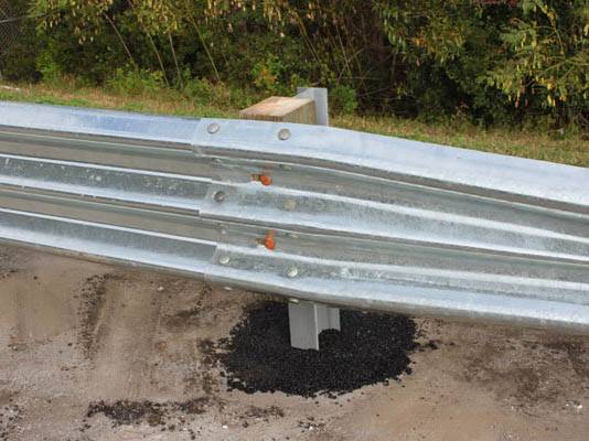
4. The barrier shall consist of a strong corrugated steel beam section mounted and tensioned on steel universal posts. End posts shall be set in concrete and intermediate posts can be driven or set in concrete.
6. The layout and the positioning of the barrier shall be as shown on the contract drawings. The details and sizes and spacing of the various components shall be as shown on the contract drawings.
8. There is no maximum length for installation. Where the line of the barrier is interrupted for an obstacle or gap, additional end anchorages shall be provided.
9. Where a barrier protects an individual short obstacle the barrier should extend from at least 30 m in front of the obstacle to at least 7.5 m or more beyond it. A minimum clearance of 1.2 m behind the barrier shall be allowed for deflection.
11. Tensioners shall consist of two longitudinal bulbs installed in brackets and shall be positioned in intervals along the barrier and bolted to the corrugated beam.
16. Safety barriers shall be erected to present a flowing alignment, with the alignment in plan not more than ± 30 mm from the prescribed alignment and no deviations in a 10 m length by more than ± 15 mm from the prescribed alignment. The height of the beam shall not depart from the prescribed height by more than ± 30 mm nor deviate in any 10 m length from the prescribed height by more than ± 10 mm.
2. The open-box beam barrier shall be used on high-speed roads where a stiffer barrier than the tensioned corrugated beam is required. The open-box barrier can be used for a double sided installation in a median.
12. Where a non-standard situation arises in the use of the crash barrier, the supplier shall obtain recommendations from the UK Transport Research Laboratory.
13. In particularly hazardous locations where vehicles with a high centre of gravity are in use, the open box barrier may be installed to a double height with two protective rails. The horizontal centreline of the second rail shall be positioned 1 m above the adjacent carriageway. The two box section rails shall be connected together with vertical straps or a single shear bolt in the centre of each connection of the rails to longer intermediate posts.
4. The minimum recommended curve for the barrier shall be 120 m radius. Tensioners shall be fitted at a maximum spacing of 70.5 m and the first tensioner shall be within 50 m of the anchorage.
1. To ensure that the vehicle crash barriers are clearly delineated, reflectorized markers shall be fixed to the barriers. The work shall consist of the fabrication supplied and fixing of reflectorized markers to vehicle crash barriers and other road side obstructions.
2. Reflectorized markers shall consist of two retro-reflective faces of minimum area 4000 mm2 on a weather proof durable backing capable of being fixed to the barrier. All metal fixings and fittings shall be galvanised or stainless steel and approved by the Engineer.
4. Reflectors shall be fixed to safety barriers and other structures where designated. Stainless steel fixings complying with BS EN ISO 3506 grade A4 shall be used to attach markers to concrete. Plastic isolation washers shall be used if the marker is galvanised.
3. The system shall be able to withstand head on and side impacts within the specified design criteria. The system shall have the performance characteristics of a conventional metal beam guard rail for strength durability and redirectional properties.
6. At the option of the Contractor, the barriers may be precast in sections not exceeding 6 m in length. In such cases the barrier shall be reinforced to ensure that information technology can be safely handled and have 2 no. lifting eyes of galvanised steel cast in at the top. The method of casting, handling and placing of barrier sections shall be proposed by the Contractor for approval by the Engineer.
5. Where adjacent barriers are put together two galvanised steel wire eyes shall be cast in to the ends to allow a steel pin to be placed through the eyes and into the road surface to secure the barrier laterally.
6. The Contractor shall propose the reinforcement in the precast barriers which shall be adequate to resist the forces and moments induced during lifting and handling.
17. Mesh, if required, shall be 10 gauge welded steel wire in accordance with BS EN 1317, where appropriate. It may be galvanised, or any other finish as directed by the Engineer.
Our W beam barrier is a roadside guardrail system suitable for containing, redirecting and shielding vehicles from roadside obstacles. Used along roadsides and highways, preventing vehicles from exiting the road way.
The Sentry Barrier TL-4 ThrieBeam System is a roadside Thrie-beam guardrail system suitable for containing, redirecting and shielding vehicles from roadside obstacles.
The Redirective, Non-Gating, Universal TAU-M Crash Cushion is designed to meet MASH TL-3 and TL-2 testing requirements in a compact, partially reusable design.

Om Wire and Wire Products Industriesis a reputed W Beam Crash Barrier Manufacturers, supplier exporter based in India. We are offering these in standard as well as in customized configurations. We are appreciated among our clients for our high end industry friendly products.
We are committed to offer products at par in excellence to international standards. For that purpose, our quality maintenance cell thoroughly tests our products during production. Backed by advanced crash barrier manufacturing facility, we are capable of fulfilling orders in stipulated time frame. Being a trusted W Beam Crash BarrierManufacturers, Suppliers Exporters in India, we are offering crash barriers at factory prices in Kolkata, India.
Sentryline II TL-3 and TL-4 Wire Rope Safety Barrier Sentryline II TL-3 and TL-4 Wire Rope Safety Barrier is an AS3845 and NCHRP350 compliant longitudinal barrier. When installed correctly the system will allow an errant vehicle to be stopped, contained or redirected in a safe manner. Features > Tested to NCHRP350 TL-3 and TL-4 > AS3845:1999 compliant and approved for use by Australian State Road Authorities > Exceptionally good vehicle control and behavior > Can be used in either edge of the road or median application > Easily installed and zero maintenance > Alternative foundation pile size options available > Easily repaired after impact > Designed to be used with Sentryline II NCHRP350 TL-3 anchor > Can be upgraded from TL-3 to TL-4 easily by the addition of another cable > Low cost patented technology available exclusively through ACP Specifications > All posts are hot dip galvanised (powder coating in various colours optional) > TL-3 top cable 770mm from ground > TL-4 top cable 790mm from ground > Typically line post footing piles are 300mm diameter x 750mm (0.05m3) > Length of need from post 5 > Posts 2 - 5 are spaced at 2m (LoN to the trigger post) > The post spacings may vary from 2 to 9m depending on the deflection requirement > Concrete to be 25Mpa > Tensioned to 25kN at 20degC. (Tension may vary depending on air temperature at time of installation, see chart in installation guidelines) Manufacturers of Road Safety Barriers | Australian Construction Products Pty Limited New South Wales Sydney 02 8708 4400 Western Austalia Perth 02 8708 4400 ACP | Sentryline II TL-3 and TL-4 Wire Rope Safety Barrier | September 2012 > Cable - 19mm 3 x 7 strand pre-stretched by 35%
SAFENCE Wire Rope Safety Barriers Supplied and Installed in India are fully in compliance with all latest Indian Roads Congress and Ministry of Road Transport and Highways Guidelines, Manuals and Standards.


 8613371530291