
wire rope drum capacity calculator manufacturer
With nearly 4,000 employees worldwide, WireCo WorldGroup is a great place for you to build a rewarding career. Our professionals enjoy the opportunities of a global manufacturing and distribution leader as well as a culture of open communication, professional growth, and friendly camaraderie that fosters innovation and problem solving.
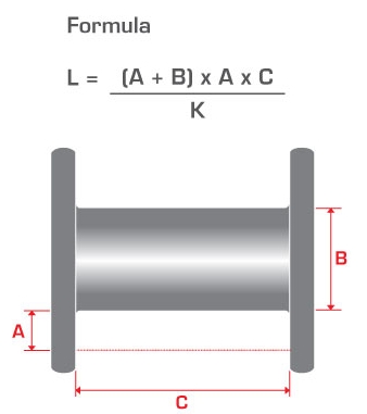
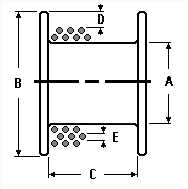
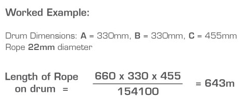
While it is virtually impossible to calculate the precise length of wire rope that can be spooled on a reel or drum, the following provides a sufficiently close approximation.
* This formula is based on uniform rope winding on the reel. It will not give correct results if the winding is non-uniform. The formula also assumes that there will be the same number of wraps in each layer. While this is not strictly correct, there is no appreciable error in the result unless the traverse of the reel is quite small relative to the flange diameter (“H”).
** The values given for “K” factors take normal rope oversize into account. Clearance (“x”) should be about 2 inches unless rope-end fittings require more.
With nearly 4,000 employees worldwide, WireCo WorldGroup is a great place for you to build a rewarding career. Our professionals enjoy the opportunities of a global manufacturing and distribution leader as well as a culture of open communication, professional growth, and friendly camaraderie that fosters innovation and problem solving.
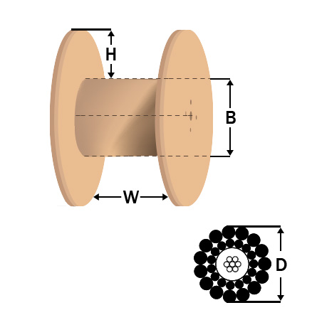
A handy tool for finding a cable drum that suits your needs - just enter your cable diameter and required length and it will return a list of matching cable drums.
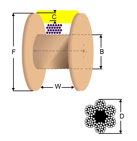
All figures given are based upon a theoretical ‘tight pack’. It is recommended that an allowance of up to 30% be made to accommodate loose winding. A lower percentage could be used if the crew are known to always wind the drums neatly!
The combined weight of cable and drum is highlighted in orange when the weight exceeds 16kg. At this weight a user may need to make a risk assessment with respect to moving and/or carrying such without assistance.
† Drums with CTS suffix have an open hub "Cable Tail Support" on their flange. This would accommodate a further couple of metre"s of cable to allow the
‡Drums with CTF suffix have cable tail supports plus an additional flange, forming an 80mm wide extra section on the side of the drum to protect the tail. Calculated capacities are shown including and excluding the extra section.
Wire rope and cable are each considered a “machine”. The configuration and method of manufacture combined with the proper selection of material when designed for a specific purpose enables a wire rope or cable to transmit forces, motion and energy in some predetermined manner and to some desired end.
Two or more wires concentrically laid around a center wire is called a strand. It may consist of one or more layers. Typically, the number of wires in a strand is 7, 19 or 37. A group of strands laid around a core would be called a cable or wire rope. In terms of product designation, 7 strands with 19 wires in each strand would be a 7×19 cable: 7 strands with 7 wires in each strand would be a 7×7 cable.
Materials Different applications for wire rope present varying demands for strength, abrasion and corrosion resistance. In order to meet these requirements, wire rope is produced in a number of different materials.
Stainless Steel This is used where corrosion is a prime factor and the cost increase warrants its use. The 18% chromium, 8% nickel alloy known as type 302 is the most common grade accepted due to both corrosion resistance and high strength. Other types frequently used in wire rope are 304, 305, 316 and 321, each having its specific advantage over the other. Type 305 is used where non-magnetic properties are required, however, there is a slight loss of strength.
Galvanized Carbon Steel This is used where strength is a prime factor and corrosion resistance is not great enough to require the use of stainless steel. The lower cost is usually a consideration in the selection of galvanized carbon steel. Wires used in these wire ropes are individually coated with a layer of zinc which offers a good measure of protection from corrosive elements.
Cable Construction The greater the number of wires in a strand or cable of a given diameter, the more flexibility it has. A 1×7 or a 1×19 strand, having 7 and 19 wires respectively, is used principally as a fixed member, as a straight linkage, or where flexing is minimal.
Selecting Wire Rope When selecting a wire rope to give the best service, there are four requirements which should be given consideration. A proper choice is made by correctly estimating the relative importance of these requirements and selecting a rope which has the qualities best suited to withstand the effects of continued use. The rope should possess:Strength sufficient to take care of the maximum load that may be applied, with a proper safety factor.
Strength Wire rope in service is subjected to several kinds of stresses. The stresses most frequently encountered are direct tension, stress due to acceleration, stress due to sudden or shock loads, stress due to bending, and stress resulting from several forces acting at one time. For the most part, these stresses can be converted into terms of simple tension, and a rope of approximately the correct strength can be chosen. As the strength of a wire rope is determined by its, size, grade and construction, these three factors should be considered.
Safety Factors The safety factor is the ratio of the strength of the rope to the working load. A wire rope with a strength of 10,000 pounds and a total working load of 2,000 pounds would be operating with a safety factor of five.
It is not possible to set safety factors for the various types of wire rope using equipment, as this factor can vary with conditions on individual units of equipment.
The proper safety factor depends not only on the loads applied, but also on the speed of operation, shock load applied, the type of fittings used for securing the rope ends, the acceleration and deceleration, the length of rope, the number, size and location of sheaves and drums, the factors causing abrasion and corrosion and the facilities for inspection.
Fatigue Fatigue failure of the wires in a wire rope is the result of the propagation of small cracks under repeated applications of bending loads. It occurs when ropes operate over comparatively small sheaves or drums. The repeated bending of the individual wires, as the rope bends when passing over the sheaves or drums, and the straightening of the individual wires, as the rope leaves the sheaves or drums, causing fatigue. The effect of fatigue on wires is illustrated by bending a wire repeatedly back and forth until it breaks.
The best means of preventing early fatigue of wire ropes is to use sheaves and drums of adequate size. To increase the resistance to fatigue, a rope of more flexible construction should be used, as increased flexibility is secured through the use of smaller wires.
Abrasive Wear The ability of a wire rope to withstand abrasion is determined by the size, the carbon and manganese content, the heat treatment of the outer wires and the construction of the rope. The larger outer wires of the less flexible constructions are better able to withstand abrasion than the finer outer wires of the more flexible ropes. The higher carbon and manganese content and the heat treatment used in producing wire for the stronger ropes, make the higher grade ropes better able to withstand abrasive wear than the lower grade ropes.
Effects of Bending All wire ropes, except stationary ropes used as guys or supports, are subjected to bending around sheaves or drums. The service obtained from wire ropes is, to a large extent, dependent upon the proper choice and location of the sheaves and drums about which it operates.
A wire rope may be considered a machine in which the individual elements (wires and strands) slide upon each other when the rope is bent. Therefore, as a prerequisite to the satisfactory operation of wire rope over sheaves and drums, the rope must be properly lubricated.
Loss of strength due to bending is caused by the inability of the individual strands and wires to adjust themselves to their changed position when the rope is bent. Tests made by the National Institute of Standards and Technology show that the rope strength decreases in a marked degree as the sheave diameter grows smaller with respect to the diameter of the rope. The loss of strength due to bending wire ropes over the sheaves found in common use will not exceed 6% and will usually be about 4%.
The bending of a wire rope is accompanied by readjustment in the positions of the strands and wires and results in actual bending of the wires. Repetitive flexing of the wires develops bending loads which, even though well within the elastic limit of the wires, set up points of stress concentration.
The fatigue effect of bending appears in the form of small cracks in the wires at these over-stressed foci. These cracks propagate under repeated stress cycles, until the remaining sound metal is inadequate to withstand the bending load. This results in broken wires showing no apparent contraction of cross section.
Experience has established the fact that from the service view-point, a very definite relationship exists between the size of the individual outer wires of a wire rope and the size of the sheave or drum about which it operates. Sheaves and drums smaller than 200 times the diameter of the outer wires will cause permanent set in a heavily loaded rope. Good practice requires the use of sheaves and drums with diameters 800 times the diameter of the outer wires in the rope for heavily loaded fast-moving ropes.
It is impossible to give a definite minimum size of sheave or drum about which a wire rope will operate with satisfactory results, because of the other factors affecting the useful life of the rope. If the loads are light or the speed slow, smaller sheaves and drums can be used without causing early fatigue of the wires than if the loads are heavy or the speed is fast. Reverse bends, where a rope is bent in one direction and then in the opposite direction, cause excessive fatigue and should be avoided whenever possible. When a reverse bend is necessary larger sheaves are required than would be the case if the rope were bent in one direction only.
Stretch of Wire Rope The stretch of a wire rope under load is the result of two components: the structural stretch and the elastic stretch. Structural stretch of wire rope is caused by the lengthening of the rope lay, compression of the core and adjustment of the wires and strands to the load placed upon the wire rope. The elastic stretch is caused by elongation of the wires.
The structural stretch varies with the size of core, the lengths of lays and the construction of the rope. This stretch also varies with the loads imposed and the amount of bending to which the rope is subjected. For estimating this stretch the value of one-half percent, or .005 times the length of the rope under load, gives an approximate figure. If loads are light, one-quarter percent or .0025 times the rope length may be used. With heavy loads, this stretch may approach one percent, or .01 times the rope length.
The elastic stretch of a wire rope is directly proportional to the load and the length of rope under load, and inversely proportional to the metallic area and modulus of elasticity. This applies only to loads that do not exceed the elastic limit of a wire rope. The elastic limit of stainless steel wire rope is approximately 60% of its breaking strength and for galvanized ropes it is approximately 50%.
Preformed Wire Ropes Preformed ropes differ from the standard, or non-preformed ropes, in that the individual wires in the strands and the strands in the rope are preformed, or pre-shaped to their proper shape before they are assembled in the finished rope.
This, in turn, results in preformed wire ropes having the following characteristics:They can be cut without the seizings necessary to retain the rope structure of non-preformed ropes.
They are substantially free from liveliness and twisting tendencies. This makes installation and handling easier, and lessens the likelihood of damage to the rope from kinking or fouling. Preforming permits the more general use of Lang lay and wire core constructions.
Removal of internal stresses increase resistance to fatigue from bending. This results in increased service where ability to withstand bending is the important requirement. It also permits the use of ropes with larger outer wires, when increased wear resistance is desired.
Outer wires will wear thinner before breaking, and broken wire ends will not protrude from the rope to injure worker’s hands, to nick and distort adjacent wires, or to wear sheaves and drums. Because of the fact that broken wire ends do not porcupine, they are not as noticeable as they are in non-preformed ropes. This necessitates the use of greater care when inspecting worn preformed ropes, to determine their true condition.

Performance of wire rope in a machine is affected by design of its sheaves and drums. Information about design of sheave and drum (diameter, the shape of the groove profiles and corresponding radius, the drum pitch and the fleet angle) is given in this article. Other useful technical information on wire ropes – measurement of diameter; generally accepted design factors; capacity of drums and reels; reserve strength; wire rope clips and wire rope end connections is also given in this article.
Rope breaking strength is determined in a standard test wherein fittings are attached to the ends of the rope and the rope is pulled in a straight line. If however, the rope passes over a curved surface (such as a sheave or pin) its strength is decreased. The amount of such reduction will depend on the severity of the bend as expressed by the D/d ratio where D is sheave / drum diameter and d is wire rope diameter. At smaller D/d ratios, the loss in strength increases quite rapidly.
It can be seen that, a rope bent around a pin of its own diameter will have only 50% of the strength attributed to it in the standard test. This is called "50% efficiency". Even at D/d ratios of 40, there may be a loss of up to 5%.
In view of above, relevant standard or statutory requirement shall be followed. In absence of such requirements, the diameter of drum or sheave shall not be less than that given in the table below.
A too narrow groove will crush the rope and damage the wires soon. In too wide groove, the rope will wear more quickly at the point of contact and also cut a false groove in the pulley. In wide groove, the rope will not have lateral support and it will flatten under load. A rope shall be supported by the groove for one third of its circumference. Recommended groove dimensions for sheave and drum are as under.
The contour at the bottom of the grooves shall be circular over an angle of approximately 120 degrees. The depth of the groove shall be not less than 0.35 times the diameter of the rope. The grooves of the drum shall be so pitched that there is, between adjacent turns of the rope, a clearance of not less than:
Sheaves shall be grooved to a depth of not less than 1.5 times the diameter of the rope. The contour at the bottom of the grooves shall be circular over an angle of approximately 130 degrees.
Where a wire rope leads over a sheave and on to a drum, the rope will not remain in alignment with the sheave but will deviate to either side depending on the width of the drum and the distance from the fixed sheave.
The fleet angle is the angle created at the point of intersection of a line drawn from the inside edge of the drum flange and along the centre line of the rope lead, and a line drawn from the centre of the drum at right angle to it. This angle is formed at the lead pulley. On a crane fitted with a grooved drum the angle should never exceed 4 degree and on a crane fitted with a flat-faced drum the angle should be between ½ degree and 2 degree maximum. If this angle is more, there will be heavy wear of the rope and groove sides.
To ensure the correct fleet angle, the following formula may be useful in finding the height of the lead pulley or the width of the drum, when one of these two measurements is known.
Diameter of a wire rope is the diameter of a circle circumscribing the strands. Care should be taken to see that it is measured correctly as shown above. The actual diameter usually varies from the nominal diameter of a rope. As per IS 2266, actual diameter can vary by -1% to 4 % of the nominal diameter of the rope.
When measuring the rope diameter, don"t measure the layer on the reel. Measure the rope when it is straight. To find the correct diameter at a point in a rope, the callipers must be placed over each pair of opposite strands, i.e. three separate readings for a six strand rope. The readings are then averaged.
The rope you are going to replace may be worn out and may measure less than the new rope. Measurement of rope to know its size shall be carried out where it is not worn out.
The reserve strength of a wire rope is the strength of the rope exclusive of the outer layer of wires, which are damaged. Following are the approximate reserve strengths expressed as a percentage of the total strengths of well lubricated new ropes.
Wire rope clips serve as an alternative to splicing and are a simple mechanical means of securing a wire rope round a thimble. They are also known as Bulldog Clips.
Wire rope clips are made from two types of materials. They are malleable iron and drop forged steel. Malleable wire rope clips are to be used only for non-critical, light duty applications with small applied loads. They should not be used for lifting or suspending load.
Several types of end connections used for overhead lifting applications are shown below. All efficiency ratings are based on the difference between the actual breaking strength of a rope and the attained breaking strength with that specific fitting. The only fitting which attains 100% efficiency are spelter sockets; provided they are properly attached.
Most of wire ropes have an actual breaking strength up to approximately 5%-15% higher than the breaking strength listed in catalogue. Due to this, wire ropes with even swaged fittings don’t fail at listed breaking strength and some manufacturers claim their assembly to have 100 % efficiency.


 8613371530291