
wire rope drive mechanism quotation

This invention relates generally to the field of mechanical systems for providing reciprocating, linear motion for a movable structure or work piece relative to a fixed structure or work piece. More particularly, the invention relates to a drive mechanism providing reciprocating, linear motion from rotational motion of a motor, using a novel cable or wire rope drive mechanism. The invention is susceptible to many possible uses and installations, examples being drive systems for use in automated instruments for processing biological samples, and stacking systems for stacking cards or card-like bodies in a tray, which happen to be of particular applications presently employed by the present inventors. However, other possible uses of the invention in different types of machines and systems will be apparent to persons skilled in the art from the following detailed description, and thus the invention relates, primarily, to reciprocating drive mechanisms for a moveable work piece. [0002]
Drive mechanisms for providing reciprocating, linear movement of a moveable work piece relative to a stationary work piece or structure are known. An example is described in the patent of Clifford W. Karl et al., U.S. Pat. No. 5,674,454, assigned to the assignee of the present invention. Generally, the "454 patent describes a stacking system for stacking flat, thin, card-like objects in a magazine. The stacking system has a moveable push plate that is used to stack the objects in the magazine. In FIG. 7 of this patent, a motor has a pinion gear with teeth which engage complementary teeth of a push rack that is coupled to the push plate. The rotation of the motor causes the push rack to move back and forth in a linear fashion, causing a push plate to move back and forth relative to the magazine and thereby providing a mechanism for stacking the objects in the magazine. [0004]
Other drive systems known in the art include Levine et al., U.S. Pat. No. 5,854,075, which describes a drive belt system for moving a carriage assembly relative to a magazine containing a plurality of slides. Other patents describing belt-type drive systems include Seto et al., U.S. Pat. No. 5,660,793; and Shindo et al., U.S. Pat. No. 5,470,533. Porte et al., U.S. Pat. No. 5,073,342, describes a simple reciprocating piston-acruated transfer mechanism. Forsstrom, U.S. Pat. No. 3,221,781 contemplates a similar type of arrangement for moving sample carriers about an analytical instrument. Other reciprocating belt and paddle-based drive mechanisms are described in the patent of William E. Seaton et al., U.S. Pat. No. 5,736,102, which is also assigned to the assignee of the present invention. [0005]
While the drive mechanism of the type described in the above-cited are work satisfactorily for many applications, the present invention is considered to be an improvement over these and other types of systems. The present drive mechanism and method is believed to provide improved reliability in extended use, and decrease the amount of maintenance for the user. Further, the design is quiet in operation. The design is easy to assemble and less costly to manufacture than systems based on the design of the above-cited Karl et al. patent. [0006] SUMMARY OF THE INVENTION
In a first aspect, a drive mechanism for providing reciprocating, liner motion for a movable work piece relative to a stationary work piece is provided. The drive system includes a motor rotating a drum in forward and reverse directions about a first fixed axis. The motor is fixedly mounted with respect to the stationary work piece, such as to a housing or other structure. The system further includes an elongate, substantially non-flexible cable having first and second ends, which are fixed with respect to the stationary work piece. The cable, which in a preferred embodiment takes the form of a wire rope, further comprises an intermediate portion extending between said first and second ends, with the intermediate portion being wound around the drum. [0007]
The drive mechanism of the invention can be installed in any type of system that may benefit from quiet, reliable operation of a reciprocating linear drive mechanism. Preferred embodiments would be in automated biological sample testing instruments, and in stacking systems for flat, thin card-like objects. However, the invention is not limited to such systems. [0010]
In another aspect of the invention, a method is provided for moving a moveable work piece relative to a stationary work piece using an elongate, substantially non-flexible wire rope or cable, the cable having a first end and a second end and an intermediate portion between the first and second ends. The method includes the step of attaching the first and second ends of said cable to a structure fixed with respect to the stationary work piece. The method includes the step of winding the intermediate portion of the cable about a drum coupled to a motor, with the motor fixed with respect to the stationary work piece. The intermediate portion of the cable is further wound around the first and second bearings, with the first and second bearings mounted to the moveable work piece such that the first bearing is positioned between the first end of the cable and the drum and the second bearing is positioned between the second end of the cable and the drum. The method includes the step of rotating the drum, whereby the step of rotating causes the first and second bearings to move relative to the drum and thereby move the moveable work piece relative to the stationary work piece.[0011]

Be it known that I, GEORGE E. WILSON, a citizen of the United States, residing at Stillwater, in the county of Washington and State of Minnesota, have invented certain new and useful Improvements in Rope Drive Mechanism; and I do declare the following to be a full, clear, and exact description of the invention, such as will enable others skilled in the art to which it appertains to make and use the same, reference being had to the accompanying drawings, and to the letters of reference marked thereon, which form a part of this specification.
Figure 1 is a side elevation illustrating my improvements. Fig. 2 is -a plan view. Fig. 3 is a side elevation showing a slightly-modified arrangement"of parts. Fig. 4 is a section through the driving-wheel illustrated in Fig. 1. Fig. 5 is a sectional view of the driven wheel and coacting parts. Fig. 6 is a sectional view through the driving-wheel when the parts are related as shown in Fig. 3.
In the drawings, A designates the cylindershaft of a thresher or other power-transmitting shaft, on which is secured a driven pulley B. Power is transmitted from a power wheel or pulley O on a suitable driving-shaft c by means of an endless rope or cable D.
- which is particularly applicable for use in connection with threshing-machines,is to provide an arrangement of parts whereby a relatively small rope or cable may be substituted for the large, heavy, and expensive belt commonly employed for transmitting motion from the engine to the cylinder-shaft of a thresher.
In order that there may be no diminution in the power and speed of the driven pulley caused by substituting such a relatively narrow and small power-transmitter for the wide belt commonly employed, I"provide means for increasing thefriotional surface which the rope or cable engages with said pulley without wrapping or winding the rope or cable entirely around the pulley.
The driven wheel or pulley B has formed therein two parallel peripheral grooves 19 b. The pulley B is relatively small, and it is not practical to wrap or wind the driving-cable D thereon, because the coils on the smooth sur face of an ordinary pulley will move or slip transversely of such surface when power is applied to the cable; but the relatively small portion of the surface of the driven pulley which would be engaged by the narrow cable would not be sufficient to produce the desired speed. Therefore I have provided means for increasing the frictional surface with which the rope or cable will engage and by which the power of the pulley B will be materially increased.
which is mounted in suitable bearin gs and arranged between the driving-wheel O and the driven wheel B. This tension-wheel is also provided with a peripheral groove, and the cable or rope D passes first from the driving pulley or wheel 0 into the groove 1) in the driven pulley and from said groove into the groove e in the tension-pulley and then to the groove 1) in the pulley B and from there back to the main power-wheel.
F designates a friction drum or pulley which is mounted between and contacts with the peripheries of both the driven pulley B and the tension-pulley E.
Both the tension-pulley E and the frictiondrum F have their bearings mounted and arranged to move longitudinally, they being shown as fitted to guides G G. These guides may be supported in any suitable manner. In case the above-described parts are employed to drive the cylinder-shaft of a threshing-machine said guides can be secured directly to the side walls of the thresher; but
My improvements are particularly applicable to the driving of the cylinders of a threshing-machine. The engine by which the power for driving the threshing mechanism is produced is placed at a relatively remote point from the thresher, and heretofore it has been considered necessary to employ a wide, heavy, and expensive belt to connect the engine drive-wheel with a pulley or wheel, as at B, on the cylinder-shaft ofthe thresher, and great care is necessary to place the two machines so that the driving and driven pulley shall be in the same straight line; but by my construction I am enabled to dispense with the said expensive and cumbersome driving-belt and employ a cheap and relatively small cable. Such a cable, however, is likely to have various inequalities in its surface, be of greater diameter at some points in its length than at others, 6120., and as the cable must be driven at a high rate of speed to impart the necessary power to the cylindershaft the tension-pulley will be subjected to sudden increases in force; but by supporting said pulley in the manner described, so that it can Vibrate to a limited extent about the axis of the shaft A, there will be no danger of the bearings of the pulley being strained or damaged. The grooves in the tension and driven pulleys are made relatively wide, so that the rope or cable will not be rendered ineffective in case there is a slight inaccuracy in alinement between the main power or driving wheel 0 and the driven wheel B.
From the description and the drawings it will be seen that withoutincreasing the width or size of the driven pulley B, I am enabled by the construction herein to drive said pulley at a high speed and that the cable or rope will be maintained taut at all times. By myconstruction also a large part of the strain of the cable or rope is taken off from the bearings of the shaft A.
I am aware that prior to my invention it has been proposed to drive a shaft by means of suitable pulleys connected by a belt with power mechanism and having frictional engagement with the shaft; also, that it has been proposed to arrange such driving-pulleys on opposite sides of the shaft to be driven, whereby the power will be uniformly applied to the shaft at diametrically opposite points and the shaft be so held against vibration that carefully-fitted and expensive bearings need not be employed; but myimprovements are clearly distinguished from such a construction as that just referred to. In myconstruction the power from the driving-wheel is taken by a relatively narrow rope or cable directly to a pulley mounted on the powerdistributing shaft, and in order that the frictional surface with which the driving rope or cable engages said pulley may be increased I arrange a friction-drum between such pulley and a supplemental tension-pulley supported at one side of the driven pulley and having a direct engagement with the powercable.
W"hat I claim is 1. In a power mechanism, the combination of a driving-wheel, a driven pulley,an endless power-transmitter connecting said drivingwheel and driven pulley, and a supplemental pulley adapted to engage with said endless transmitter at points between said drivingwheel and driven pulley and supported to move bodily,independently of either the driving-wheel or driven pulley, toward and from said wheel or pulley, substantially as set forth.
2. In a power mechanism, the combination of a revoluble driving member, a revoluble driven member, an endless power-transmitter connecting said members, and a supplemental pulley adapted to engage with the power-transmitter and mounted to move, independently of the said driving and driven members, bodily in an arc concentric with the axis of one of said main members, and also toward and from said axis, substantially as set forth.
3. In a power mechanism, the combination of a driving-wheel, a driven pulley having two peripheral grooves formed therein, an endless power-transmitter connecting said driving-wheel and driven pulley and having a portion fitted in each of the grooves in the said driven pulley, and a supplemental pulley having a peripheral groove receiving a portion of the endless power-transmitter intermediate of the portions of said transmitter engaging with the driven pulley, said supplemental pulley being mounted to move bodily toward and from the driven pulley, independently of any movement of said driven pulley, substantially as set forth.
4. In a rope or cable driven power mechanism, the combination of a main drivingwheel, 0, the driven wheel, B, the tension pulley or wheel arranged to automatically move to and from said driven wheel, an endless cable connecting all of said wheels and a friction-drum interposed between the tension-wheel and the driven pulley, substantially as set forth.
5. In a cable or rope drive mechanism, the combination of a driving-wheel, a driven pulley, guides supported at the axis of the driven pulley, a tension-pulley mounted in bearings fitted to said guides to move toward and from the driven pulley a friction-drum mounted in bearings fitted to said guides, between the tension-pulley and the driven wheel, and an endless cable extending from the drivingwheel around the driven wheel and the tension-pulley, substantially as set forth.
6. The combination of a driven Wheel, a driving-wheel, a tension-pulley arranged between the driving-wheel and driven wheel, a bearing for the tension-pulley adapted to vibrate about the axis of one of said wheels, a friction-drum mounted to vibrate With said tension-pulley and contacting therewith and with one of said Wheels, and an endless powertransmitting connection between the two wheels and the tension-pulley, substantially asset forth; r
7. The combination of a driving-Wheel, a driven Wheel, a tension-pulley arranged between said wheels and adapted to vibrate in an arc concentric with one of them, a frictiondrum mounted betweenand in contact with said pulley andone of said wheels, and an I endless power-transmitter connecting said, wheels and said pulley, substantially as set forth.
8. The combination of a driving-wheel, a driven wheel, arms supported to vibrate about by said arms, and contacting with the said 40 pulley and one of the wheels, and an endless power-transmitter connecting said wheels and the pulley, substantially as set forth.

Our team understands that choosing the right cable assembly manufacturer, and pulleys for your cable assemblies requires thoughtful consideration, from bearing life, to minimum pulley diameter. Let Sava"s engineering expertise guide you toward the best selection of wire rope pulley wheels.
When cable is used over pulleys, the cable life can be significantly prolonged by proper pulley groove design. Laboratory tests on wire rope pulleys prove that improper groove design reduces cable bending life up to 90%. These same tests show that doubling a pulley diameter can increase cable bending life up to thirteen times what is otherwise typical. Also, pulley diameters less than sixteen rope diameters fall into a range in which cable life is relatively low.

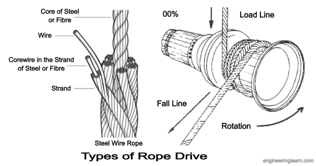
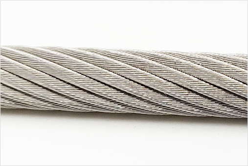
Wire rope is constructed of multiple strands of wire that are twisted and braided together to form a spiral design or helix. Once the separate wires are shaped into a solid form, they become a single wire with greater strength because the individual wires equalize pressure and have greater flexibility than the individual strands.
To further enhance the strength of wire ropes, they are grouped and wound together to produce cables, which adds to their usefulness as a means of support, ability to lift, and give structural stability.
A key factor in wire rope is the lay of the strands, which can be regular or lang. With regular lay, or right and ordinary lay, the strands are wound from left to right with the wires laid in the opposite direction of the lay of the strands. With lang lay, the wires are wound in the same direction.
The structure and design of wire rope produces a final product that has superior strength, excellent strength flexibility, and the ability to handle constant bending stress as well as being weather resistant.
Wire rope is one of those products that has found a place in a wide variety of industries since it can be adapted and shaped to fit several applications. It can be found as a tow cable for boats and airplanes or in the movie industry as a harness for stunt artists. The varied uses of wire rope have made it an essential part of operations that require a rope with strength, endurance, and flexibility.
In the aerospace industry, wire ropes, or Bowden cables, connect pedals and levers in the airplane cockpit to send power to aircraft systems to control the airplane. The things that are controlled by wire ropes are propeller pitch, cowl flaps, and throttle. Wire ropes on aircraft are insulated to avoid vibrations.
Wire rope is extensively used in the auto industry for a wide variety of applications due to its versatility and strength. It is used for raising windows and opening and closing sunroofs. Other uses include steering wheels, cables, exhausts, springs, sunroofs, doors, and seat components. In the manufacturing process, wire rope is used to hoist vehicles, move large body parts, and on hoists and cranes.
The construction industry has a greatest reliance on wire rope because of the need to lift and lower heavy loads. Wire rope used in construction must have extremely high strength and exceptional performance for safety reasons and efficiency. Larger versions of wire rope are used for suspension bridges and supporting concrete columns.
The main use of wire rope in food processing is for lifting, moving loads, and other heavy tasks. Finished products or raw materials require being moved in storage units and processing centers. The strength and endurance of wire rope makes it possible to move these materials. Wire rope for food processing must be able to withstand regular chemical cleaning.
As with other industries, the oil and gas industry needs strong and reliable equipment for moving heavy equipment. In ocean drilling, machinery is dropped into the ocean using wire rope to securely hold devices to be dropped to extreme depths. Wire ropes are designed to withstand the extreme pressure and stress required. A further use of wire ropes for drilling operations is to maintain stability in the drilling lines. One of the unique features of oil rig wire rope is its length, which can exceed 10,000 feet.
A very common use for wire rope is mooring and towing of sea and freshwater boats and vessels. In the shipbuilding industry, wire rope is used to secure lifeboats as well as lower them into the water. On sailboats, wire rope is used to lift and lower sails. The benefit of using wire rope is its resistance to corrosion and rust caused by salt water and ocean mist.
The skiing industry, much like heavy equipment industries, uses wire rope to hold cars, lifts, or chairs to transport skiers up the mountain. This type of wire rope comes in several varieties depending on the size of the mountain. The benefits of wire rope for skiing is its dependability, guaranteed safety, and reliability. The main challenge of wire rope for use in sports is the weather conditions it must endure.
Since the beginnings of amusement parks, wire rope has been an essential part of attraction construction. It is used to bring roller coaster cars to the top of the ride, hold swings, and pull various vehicles through attractions. One of the main concerns of public amusement parks is safety since rides are filled with powerful machinery designed to operate continuously.
Making the dangerous and exciting shots in movies requires well planned safety precautions. One of the aspects of that planning is wire rope that is designed to protect performers when they are engaged in dangerous and life threatening shots. Dependable wire ropes are ideal since they have the flexibility, strength, endurance, and versatility to be adapted to any conditions.
In architecture and design, wire rope has been used for guard rails, balustrades, and roof construction. In innovative green buildings where plants grow along the surface of the building, the plants grow along specially designed vertical wire ropes that are capable of withstanding weather conditions.
A common use of wire rope is in railings, which are safe, durable, and provide a pleasing aesthetic appeal. The use of wire rope for railings provides protection without obstructing the view from a building. This aspect of wire rope is one of the reasons that it is used for large architectural projects since it blends into the structure without interiors with the architectural design.
The types of wire rope are determined by the number of wires in each strand and how many are in the rope, which is defined by a two number system with the first number being the number of wires and the second being the number of wires in each strand. For example, a 6x19 wire rope has 6 wires in 19 strands.
There are a wide variety of products that are produced using wire rope. The demand for wire rope products is due to its strength, durability, and reliability. Since the basic purpose of wire rope is to lift and move heavy materials and items, the most common type of wire rope product is the wire rope sling.
Though the construction of wire rope slings is very similar for all types, there are certain variations applied to slings to adjust them to fit different applications. Slings are configured in various ways to fit different types of loads. These changes are referred to as hitches.
Bridle Hitch: The multiple leg or bridle hitch style has more than one wire rope sling attached to equalize the load and control balance. They reduce load damage by using fixed points on the load and offer easier rigging when hooked into fixed lifting points. .
Single Part Wire Rope Sling: The eye for a single part wire rope sling is formed by looping the wire rope back on to the rope. The end of the rope is attached by a clamp or being woven by hand or mechanically into the rope body. Single part wire rope slings use a single wire rope to produce the sling.
Braided Wire Rope Sling: A braided wire rope sling is made by braiding wire ropes to form a sling. The increased number of strands enhances the strength of the sling and its load capacity. Braiding can be done with three to nine wire ropes.
Cable Laid Wire Rope Sling: Cable laid wire rope slings are made from combining several smaller wire ropes to form a flexible, easy to handle, and kink resistant sling.
Woven Eye Wire Rope Sling: For the woven eye version of a wire rope sling, the eye is formed by weaving the wire rope into itself after forming the loop. It is designed to reduce the chance of the sling catching or being hung up when lifting.
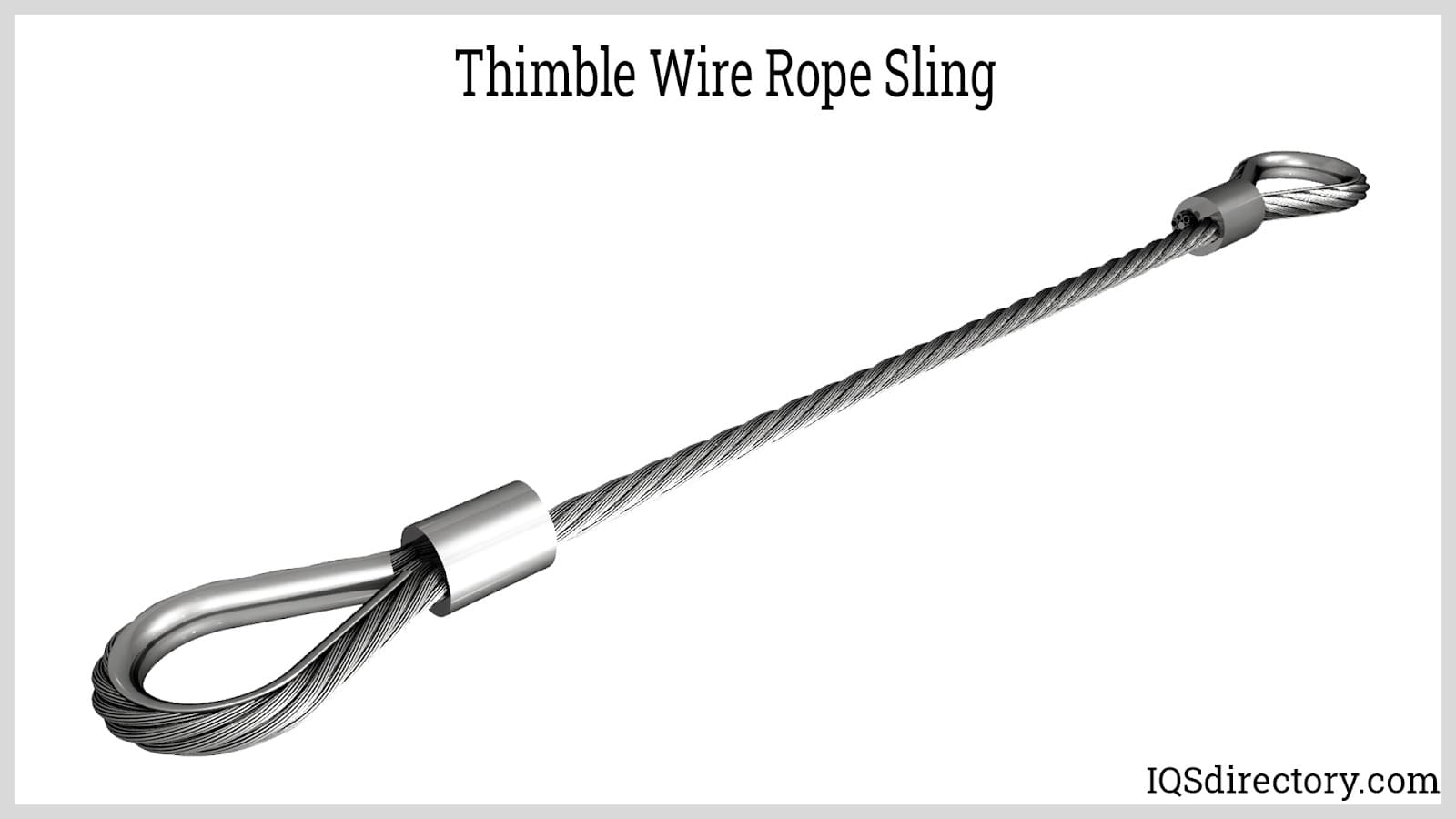
Thimble Wire Rope Sling: To add to the strength of wire rope slings and lessen the stress on a small area of the eye, a thimble, a U shaped piece into which the wire rope fits, is placed in the eye, which helps the sling to retain its natural shape. The thimble is positioned to prevent the hook or load from coming in contact with the wire rope.
Endless Wire Rope Sling:Endless wire rope slings are adaptable slings without a set wear point. They can be manufactured in a wide range of sizes and are used in applications where headroom may be a problem. Endless wire rope slings are made by splicing the ends of a piece of wire rope together or by tucking strand ends into the body to form a core with a tucked position the opposite of the core position. They are also referred to as grommet wire rope slings.
Coiled wire rope is made from bundles of small metal wires that are twisted into a coil. It comes in many varieties and is easy to store since it does not require a spool. Coiled wire rope is produced in coils. When it is not in use, it springs back into a coil, which makes it easy to handle.
Cable wire rope is a type of high strength rope, made of several individual filaments. These filaments are twisted into strands and helically wrapped around a core. One of the most common types of wire rope cable is steel cable.
Push pull wire rope assemblies are used to send force and are used in the aircraft, exercise, medical, automotive, and office equipment industries. Unlike using a single heavy wire, push pull assemblies made with wire rope are stiffer and have a larger bend radii for smoother motion of the wire.
Wire rope assemblies include wire rope and various parts and components that have been added to the wire rope to enhance its function. The connectors for a wire rope assembly are designed to connect the assembly to hooks, equipment, or machines as well as other wire rope assemblies. The central part of a wire rope assembly is the wire rope, which determines the type and kind of work the assembly can perform.
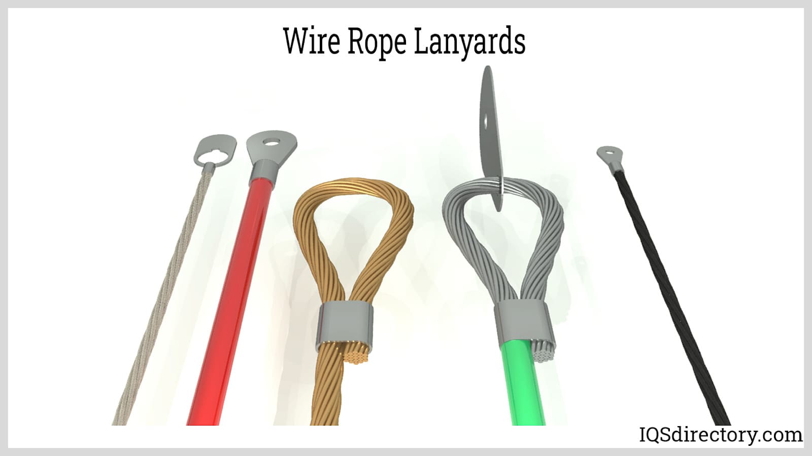
Wire rope lanyards are a standard wire rope product that have a multitude of uses. They are produced using the same process that is used to produce wire rope with the same numbering categorizing system. Lanyards are used to hold fasteners, hardware, or components to prevent loss of an item or prevent injury.
In many ways, wire rope is a form of machine with multiple moving parts. Normally, when we think of a machine, we imagine a device with a motor, drives, and gears. Wire rope does not have any of those components but does fit the definition of being a complex mechanism. It has moving parts that work together to move heavy materials and loads.
The main function of wire rope is to do heavy lifting, which is very dependent on wire rope slings. The type of sling is determined by the quality of the wire rope used to form them and whether several ropes have been braided or wound together.
Wire is the smallest part of wire rope but makes up the various strands. The composition of the wire can be steel, iron, stainless steel, copper, or other types of metal wires and are produced in different grades. The individual wires can be coated or bright, meaning uncoated.
Strands are sets of wires that are twisted together and are placed in a helical pattern around the core. The size of the wire determines its abrasive qualities with larger wires being more abrasive and less flexible than smaller ones.
The core is the center of the wire rope and serves as a support for the strands and helps the wire rope keep its position when it is under stress or bearing a load.
Lubrication is applied during the manufacturing process to reduce friction between the wires and strands as well as protection from corrosion and rust. The tight winding of the wires enhances the ability of the wire rope to retain the lubrication which is essential to its longevity.
The purpose of applying lubricant is to limit the friction between the cables to increase the useful life of the wire rope. In certain applications, such as space travel, lubricants can be hazardous and cause equipment to malfunction. In those instances, non-lubricated wire rope is used, which is referred to as dry wire rope or cable.
Of all of the products that are made from wire rope, slings are the most common and widely used. These looped wire ropes come in different varieties and grades depending on the type of wire used. Also, to enhance wire sling performance, several wire ropes may be wound together to form a sturdier and more reliable sling.
Flemish splicing is a method for repairing a wire rope and involves breaking the wire rope in half and tying it back together. In the Flemish method, the wire rope is tied back on itself and swaged down a sleeve over the unbroken wire rope to create the new eye.
Prior to placing the wire rope into the holding device used to shape the eye, a steel compression sleeve is placed on the rope, which will be used to secure and hold the eye.
Once the proper size is achieved, the unwound strands are rewound in the reverse order of their former positioning. If the wire rope has a right hand lay, it is rewound using a left hand lay. The opposite is true if the wire rope has a left hand lay, then it is rewound using a right hand lay. By using this technique, a friction mold is formed for the splicing of the sling.
Anti-rotational wire rope resists the forces of rotation by having opposing layers of helical stands. By winding the wire rope with oppositional strands, the wire rope is guaranteed to not unwind in clockwise or counterclockwise directions. The key to anti-rotational wire rope is to ensure that the outer diameter is static.
In the manufacture of anti-rotational wire rope, counter stranded filaments have vacant spaces between them. To make the wire rope anti-rotational, it is tightly twisted in the counterclockwise direction, which tightens the spaces between the filaments. If the wire rope is turned in a counterclockwise direction, the strands tighten around each other creating a spring force.
The tails and stray wires of the wire rope have to be straightened and properly formed before applying the compression sleeve. Once the sleeve has been placed, it is carefully checked to be sure that it is accurately engaged.
Prior to placing the wire rope sling in the swaging die, the die has to be thoroughly lubricated. Once the die is set, the wire rope‘s compression sleeve and the wire rope are compressed using several hundred thousand pounds of force. The swaging process alters the dimensions of the wire rope and compression sleeve to form a tight connection for the correct diameter for the sling connection. As force is applied, the compression sleeve is turned so that pressure is evenly applied.
There are several types of metal wires that are used to produce wire rope, which include steel, stainless steel, galvanized, aluminum, nickel alloy, bronze, copper, and titanium. Carbon steel is the most common type of wire rope material.
Wire ropes are made using uncoated bright wire, which is high-carbon steel. The type of steel depends on the requirements of the wire and its tensile strength and its fatigue and wear resistance.
Galvanized wire rope is treated with zinc to prevent corrosion and can be used in harsh conditions and environments. It is a cost effective alternative to stainless steel but does not have the same corrosion resistance. Galvanized wire rope is stronger than stainless steel of the same grade and size. Vinyl coated galvanized wire rope is easy to handle and flexible.
Stainless steel wire rope is corrosion and rust resistant. It is available in types 316 and 304 with 316 having greater corrosion resistance. Stainless steel wire rope can be used for marine applications, acidic environments, and other demanding conditions. It is produced with the appropriate tolerances and composition to meet the needs of the application.
Multiple strands of copper are braided into a round hollow shape, which is pressed into the desired width and thickness. Copper wire rope has exceptional flexibility, an exceptional life span and can be used as part of electrical components.
Bronze wire rope inhibits sparking and is corrosion resistant. It is made from preformed wire to ensure that it maintains its shape and does not unravel when cut. Bronze wire rope is abrasion resistant and very flexible with a crush resistant core.
Inconel wire can be used in applications that reach temperatures as high as 2000° F and is oxidation and corrosion resistant. It is non-magnetic and has excellent resistance to chloride based corrosion cracking. Inconel wire rope can be used with nuclear generators and chemical and food processing.
Titanium wire rope comes in several grades with grade two being 99% pure. It is easily formable and weldable. Titanium wire rope is commonly used in chemical processing and marine hardware.
For wire rope to perform properly, it needs to have proper care. Wire rope is an essential tool necessary to perform a wire range of lifting and moving jobs. It is important that it be handled, treated, installed, stored, and treated correctly to prolong its life and perform to the highest standards.
Seizing should be completed on both ends of the wire rope, which will protect it from loosening. If this is done improperly, the wire rope can become distorted. Wire rope that is properly seized evenly distributes the load.
Wire rope is stored on reels or coils and has to be carefully handled when it is being removed. To ensure excellent performance, the wire rope should not be dropped during removal. If the reel or coil is dropped or damaged, it can make handling the wire rope difficult and cumbersome. As the wire rope is removed from the reel, check to see that the reel is rotating as the wire is removed.
Wire rope is depended on for heavy lifting and is trusted to keep a load and people safe. As with all heavy duty equipment, wire rope must have a regular inspection schedule and be visually assessed during use.
Broken Strands – An easy way to check for broken strands is to run a cloth over the length of the wire. Broken strands that are found in critical areas, such as parts that pass through pulleys or sections that are regularly flexed, rubbed, or constantly worked must be replaced and repaired.
Internal wear – This can be tested by flexing the wire rope, which indicates if the interior has deteriorated, experienced fatigue, or become distorted.
For wire rope to perform at the highest level, it has to be stored in a well ventilated environment that is dry, covered, and not in contact with the floor. The avoidance of high moisture or damp conditions is an absolute necessity. While the wire rope is in storage, it should be moved regularly to keep the lubricant from wearing off.
Though lubricant is applied during the manufacturing of wire rope, it wears off during use. Lubrication is the key to the performance of wire rope because it helps prevent abrasion as the wires rub against one another. Relubrication should be applied after the original lubricant has worn off.
Wire rope is a tool and must be cleaned regularly as with any form of machinery. This can be accomplished with different types of petroleum solvents and a wire brush. Mechanical methods of cleaning can include compressed air or a steam cleaner. Once the cleaning process is completed, the wire rope should be lubricated for protection.
There are several substances that can harm a wire rope. They include salt water, brine, acid, various gasses, and humidity. To avoid the intrusion of these negative effects, when a job is completed and the wire rope is to be stored, it should be cleaned, lubricated, and placed in proper storage.
When wire rope is being removed from a spool or being spooled, the operation must be performed smoothly with the spool rotating at a constant speed and rhythm. This will help prevent kinking or binding.
When a wire rope shows a reduction in diameter, has broken wires, kinks, nodes, flattened surfaces, out of place outer wires, damage from heat exposure, corrosion damage, or the formation of unexpected loops, it should be removed and replaced or be repaired.
Wire rope is regulated by the Occupational Safety and Health Administration (OSHA) as part of the regulations for cranes and derricks in construction as part of 29 CFR 1926.1413, which went into effect on November 8, 2010.
The inspection of wire ropes is on three levels: shift, monthly, and annually. Shift and monthly inspections can be completed by an approved operator, while annual inspection must be completed by certified personnel.
As with the shift and monthly inspections, the annual inspection follows the guidelines for the shift inspection. This inspection must be completed by certified personnel. The entire surface of the wire rope has to be inspected, with attention to:
Annual inspections can be excused if it is not possible due to the wire ropes setup or configuration or the location of the work site. It must be completed within six months. If any deficiencies are found, the wire rope must be repaired or removed. For some deficiencies, it is possible to keep the wire rope in use but have them regularly monitored.
Wire rope is a form of metal tool that is constructed of multiple strands of wire that are twisted and braided together to form a spiral design or helix.
To further enhance the strength of wire rope, they are grouped and wound together to produce cables, which adds to their usefulness as a means of support, ability to lift, and give structural stability.
The types of wire rope are determined by the number of wires in each strand and how many are in the rope, which is defined by a two number system with the first number being the number of wires and the second being the number of wires in each strand.
In stricter senses, the term wire rope refers to a diameter larger than 9.5 mm (3⁄8 in), with smaller gauges designated cable or cords.wrought iron wires were used, but today steel is the main material used for wire ropes.
Historically, wire rope evolved from wrought iron chains, which had a record of mechanical failure. While flaws in chain links or solid steel bars can lead to catastrophic failure, flaws in the wires making up a steel cable are less critical as the other wires easily take up the load. While friction between the individual wires and strands causes wear over the life of the rope, it also helps to compensate for minor failures in the short run.
Wire ropes were developed starting with mining hoist applications in the 1830s. Wire ropes are used dynamically for lifting and hoisting in cranes and elevators, and for transmission of mechanical power. Wire rope is also used to transmit force in mechanisms, such as a Bowden cable or the control surfaces of an airplane connected to levers and pedals in the cockpit. Only aircraft cables have WSC (wire strand core). Also, aircraft cables are available in smaller diameters than wire rope. For example, aircraft cables are available in 1.2 mm (3⁄64 in) diameter while most wire ropes begin at a 6.4 mm (1⁄4 in) diameter.suspension bridges or as guy wires to support towers. An aerial tramway relies on wire rope to support and move cargo overhead.
Modern wire rope was invented by the German mining engineer Wilhelm Albert in the years between 1831 and 1834 for use in mining in the Harz Mountains in Clausthal, Lower Saxony, Germany.chains, such as had been used before.
Wilhelm Albert"s first ropes consisted of three strands consisting of four wires each. In 1840, Scotsman Robert Stirling Newall improved the process further.John A. Roebling, starting in 1841suspension bridge building. Roebling introduced a number of innovations in the design, materials and manufacture of wire rope. Ever with an ear to technology developments in mining and railroading, Josiah White and Erskine Hazard, principal ownersLehigh Coal & Navigation Company (LC&N Co.) — as they had with the first blast furnaces in the Lehigh Valley — built a Wire Rope factory in Mauch Chunk,Pennsylvania in 1848, which provided lift cables for the Ashley Planes project, then the back track planes of the Summit Hill & Mauch Chunk Railroad, improving its attractiveness as a premier tourism destination, and vastly improving the throughput of the coal capacity since return of cars dropped from nearly four hours to less than 20 minutes. The decades were witness to a burgeoning increase in deep shaft mining in both Europe and North America as surface mineral deposits were exhausted and miners had to chase layers along inclined layers. The era was early in railroad development and steam engines lacked sufficient tractive effort to climb steep slopes, so incline plane railways were common. This pushed development of cable hoists rapidly in the United States as surface deposits in the Anthracite Coal Region north and south dove deeper every year, and even the rich deposits in the Panther Creek Valley required LC&N Co. to drive their first shafts into lower slopes beginning Lansford and its Schuylkill County twin-town Coaldale.
The German engineering firm of Adolf Bleichert & Co. was founded in 1874 and began to build bicable aerial tramways for mining in the Ruhr Valley. With important patents, and dozens of working systems in Europe, Bleichert dominated the global industry, later licensing its designs and manufacturing techniques to Trenton Iron Works, New Jersey, USA which built systems across America. Adolf Bleichert & Co. went on to build hundreds of aerial tramways around the world: from Alaska to Argentina, Australia and Spitsbergen. The Bleichert company also built hundreds of aerial tramways for both the Imperial German Army and the Wehrmacht.
In the last half of the 19th century, wire rope systems were used as a means of transmitting mechanical powercable cars. Wire rope systems cost one-tenth as much and had lower friction losses than line shafts. Because of these advantages, wire rope systems were used to transmit power for a distance of a few miles or kilometers.
Steel wires for wire ropes are normally made of non-alloy carbon steel with a carbon content of 0.4 to 0.95%. The very high strength of the rope wires enables wire ropes to support large tensile forces and to run over sheaves with relatively small diameters.
In the mostly used parallel lay strands, the lay length of all the wire layers is equal and the wires of any two superimposed layers are parallel, resulting in linear contact. The wire of the outer layer is supported by two wires of the inner layer. These wires are neighbors along the whole length of the strand. Parallel lay strands are made in one operation. The endurance of wire ropes with this kind of strand is always much greater than of those (seldom used) with cross lay strands. Parallel lay strands with two wire layers have the construction Filler, Seale or Warrington.
In principle, spiral ropes are round strands as they have an assembly of layers of wires laid helically over a centre with at least one layer of wires being laid in the opposite direction to that of the outer layer. Spiral ropes can be dimensioned in such a way that they are non-rotating which means that under tension the rope torque is nearly zero. The open spiral rope consists only of round wires. The half-locked coil rope and the full-locked coil rope always have a centre made of round wires. The locked coil ropes have one or more outer layers of profile wires. They have the advantage that their construction prevents the penetration of dirt and water to a greater extent and it also protects them from loss of lubricant. In addition, they have one further very important advantage as the ends of a broken outer wire cannot leave the rope if it has the proper dimensions.
Stranded ropes are an assembly of several strands laid helically in one or more layers around a core. This core can be one of three types. The first is a fiber core, made up of synthetic material or natural fibers like sisal. Synthetic fibers are stronger and more uniform but cannot absorb much lubricant. Natural fibers can absorb up to 15% of their weight in lubricant and so protect the inner wires much better from corrosion than synthetic fibers do. Fiber cores are the most flexible and elastic, but have the downside of getting crushed easily. The second type, wire strand core, is made up of one additional strand of wire, and is typically used for suspension. The third type is independent wire rope core (IWRC), which is the most durable in all types of environments.ordinary lay rope if the lay direction of the wires in the outer strands is in the opposite direction to the lay of the outer strands themselves. If both the wires in the outer strands and the outer strands themselves have the same lay direction, the rope is called a lang lay rope (from Dutch langslag contrary to kruisslag,Regular lay means the individual wires were wrapped around the centers in one direction and the strands were wrapped around the core in the opposite direction.
Multi-strand ropes are all more or less resistant to rotation and have at least two layers of strands laid helically around a centre. The direction of the outer strands is opposite to that of the underlying strand layers. Ropes with three strand layers can be nearly non-rotating. Ropes with two strand layers are mostly only low-rotating.
Stationary ropes, stay ropes (spiral ropes, mostly full-locked) have to carry tensile forces and are therefore mainly loaded by static and fluctuating tensile stresses. Ropes used for suspension are often called cables.
Track ropes (full locked ropes) have to act as rails for the rollers of cabins or other loads in aerial ropeways and cable cranes. In contrast to running ropes, track ropes do not take on the curvature of the rollers. Under the roller force, a so-called free bending radius of the rope occurs. This radius increases (and the bending stresses decrease) with the tensile force and decreases with the roller force.
Wire rope slings (stranded ropes) are used to harness various kinds of goods. These slings are stressed by the tensile forces but first of all by bending stresses when bent over the more or less sharp edges of the goods.
Technical regulations apply to the design of rope drives for cranes, elevators, rope ways and mining installations. Factors that are considered in design include:
Donandt force (yielding tensile force for a given bending diameter ratio D/d) - strict limit. The nominal rope tensile force S must be smaller than the Donandt force SD1.
The wire ropes are stressed by fluctuating forces, by wear, by corrosion and in seldom cases by extreme forces. The rope life is finite and the safety is only ensured by inspection for the detection of wire breaks on a reference rope length, of cross-section loss, as well as other failures so that the wire rope can be replaced before a dangerous situation occurs. Installations should be designed to facilitate the inspection of the wire ropes.
Lifting installations for passenger transportation require that a combination of several methods should be used to prevent a car from plunging downwards. Elevators must have redundant bearing ropes and a safety gear. Ropeways and mine hoistings must be permanently supervised by a responsible manager and the rope must be inspected by a magnetic method capable of detecting inner wire breaks.
The end of a wire rope tends to fray readily, and cannot be easily connected to plant and equipment. There are different ways of securing the ends of wire ropes to prevent fraying. The common and useful type of end fitting for a wire rope is to turn the end back to form a loop. The loose end is then fixed back on the wire rope. Termination efficiencies vary from about 70% for a Flemish eye alone; to nearly 90% for a Flemish eye and splice; to 100% for potted ends and swagings.
When the wire rope is terminated with a loop, there is a risk that it will bend too tightly, especially when the loop is connected to a device that concentrates the load on a relatively small area. A thimble can be installed inside the loop to preserve the natural shape of the loop, and protect the cable from pinching and abrading on the inside of the loop. The use of thimbles in loops is industry best practice. The thimble prevents the load from coming into direct contact with the wires.
A wire rope clip, sometimes called a clamp, is used to fix the loose end of the loop back to the wire rope. It usually consists of a U-bolt, a forged saddle, and two nuts. The two layers of wire rope are placed in the U-bolt. The saddle is then fitted to the bolt over the ropes (the saddle includes two holes to fit to the U-bolt). The nuts secure the arrangement in place. Two or more clips are usually used to terminate a wire rope depending on the diameter. As many as eight may be needed for a 2 in (50.8 mm) diameter rope.
The mnemonic "never saddle a dead horse" means that when installing clips, the saddle portion of the assembly is placed on the load-bearing or "live" side, not on the non-load-bearing or "dead" side of the cable. This is to protect the live or stress-bearing end of the rope against crushing and abuse. The flat bearing seat and extended prongs of the body are designed to protect the rope and are always placed against the live end.
An eye splice may be used to terminate the loose end of a wire rope when forming a loop. The strands of the end of a wire rope are unwound a certain distance, then bent around so that the end of the unwrapped length forms an eye. The unwrapped strands are then plaited back into the wire rope, forming the loop, or an eye, called an eye splice.
A Flemish eye, or Dutch Splice, involves unwrapping three strands (the strands need to be next to each other, not alternates) of the wire and keeping them off to one side. The remaining strands are bent around, until the end of the wire meets the "V" where the unwrapping finished, to form the eye. The strands kept to one side are now re-wrapped by wrapping from the end of the wire back to the "V" of the eye. These strands are effectively rewrapped along the wire in the opposite direction to their original lay. When this type of rope splice is used specifically on wire rope, it is called a "Molly Hogan", and, by some, a "Dutch" eye instead of a "Flemish" eye.
Swaging is a method of wire rope termination that refers to the installation technique. The purpose of swaging wire rope fittings is to connect two wire rope ends together, or to otherwise terminate one end of wire rope to something else. A mechanical or hydraulic swager is used to compress and deform the fitting, creating a permanent connection. Threaded studs, ferrules, sockets, and sleeves are examples of different swaged terminations.
A wedge socket termination is useful when the fitting needs to be replaced frequently. For example, if the end of a wire rope is in a high-wear region, the rope may be periodically trimmed, requiring the termination hardware to be removed and reapplied. An example of this is on the ends of the drag ropes on a dragline. The end loop of the wire rope enters a tapered opening in the socket, wrapped around a separate component called the wedge. The arrangement is knocked in place, and load gradually eased onto the rope. As the load increases on the wire rope, the wedge become more secure, gripping the rope tighter.
Poured sockets are used to make a high strength, permanent termination; they are created by inserting the wire rope into the narrow end of a conical cavity which is oriented in-line with the intended direction of strain. The individual wires are splayed out inside the cone or "capel", and the cone is then filled with molten lead-antimony-tin (Pb80Sb15Sn5) solder or "white metal capping",zincpolyester resin compound.
Koetsier,Teun; Ceccarelli, Marc (2012). Explorations in the History of Machines and Mechanisms. Springer Publishing. p. 388. ISBN 9789400741324. Archived from the original on 31 March 2017. Retrieved 9 April 2014.
Donald Sayenga. "Modern History of Wire Rope". History of the Atlantic Cable & Submarine Telegraphy (atlantic-cable.com). Archived from the original on 3 February 2014. Retrieved 9 April 2014.

Body Wire and fiber ropes used in rigorous CBOS (cyclic bend over sheave) applications were investigated. Small diameter stainless steel, tungsten, and Vectran® ropes were tested over small sheaves at high loads and cycle speeds. Sheaves were made with Al6061-T6511 and Al7075-T651 and were coated with 0.002” hard coat anodize; some were dipped in Teflon®. Tungsten was found to have the highest bending fatigue resistance. Vectran® melted under the fast cycle speeds due to rope temperature…Expand

A synthetic fiber rope, which is lightweight and has a high tensile strength and flexibility, is receiving much attention as a replacement for a stainless steel wire rope. To exploit the maximum tensile strength of the rope, it is essential to develop a terminal fixation method with the sufficient fixing force. However, practical difficulty exists in the case of the synthetic fiber ropes because the synthetic fiber ropes have very small frictional coefficients compared with a stainless wire…Expand

Flexible cable realize high flexibility and torque force transmission, ideal for drive cable for atherectomy, impeller, anchoring, and device release mechanism.
Gold wire features 99.99% purity and offers researchers a noble metal with biological inertness. Gold is softer than platinum and this feature may be used as an advantage in some applications.
... kPSI the more brittle the wire is but the better it retains its shape. The high kPSI wire is good for making straight electrodes that need to penetrate through tissue. The low kPSI is a softer more flexible ...
our magnesium alloy wire adopts the technical of super plasticity forming to improve the shortcomings of the low plasticity, which has the excellent plasticity much more than the normal magnesium alloys under the room ...
The name LeBus has been around the oil field industry since it was just a blacksmith shop in 1900. LeBus started out by manufacturing speciality tools for the booming west Texas oil fields. Tool pushers and/or owners would see a specific need for a new tool and LeBus would forge the new tools on demand. Soon LeBus was into the manufacturing and selling of fishing tools, drill collars, tool joints and rotary bits. LeBus manufactured the "Eureka Pipe Wrench" and the "Slip Socket Overshot". The common element in each case was the hoisting machinery, specifically the drum and wire rope, which was the main "workhorse" of the drilling rig. LeBus noticed that the wire rope would not lay in a consistent pattern on the drum. This caused undue wear and scrubbing of the wire rope. Something better was on the horizon.
The LRM®XXI Diagnostic System is very helpful in evaluating the technical conditionof the tested wire rope in full cross section and in full available length of wire rope in the fastest way. MRT Equipment can detect weakness section of the ropeexpressed in percentage of loss of metallic area.
The LRM®XXI Wire Rope Diagnostic System enables detecting long changes in the rope cross-section due to corrosion and wear (LMA sensor) and local changes, e.g. broken wires, corrosion pitting and other local rope damage (LF sensor).
The inspection results are said to be reliable, accurate and repeatable. Due to the use of Magnetic method for testing of wire ropes the external coating(e.g. grease and anti-corrosion protection) does not influence the quality of the results.
a) Loss of Metallic Area (LMA) Sensor, enables the localization and evaluation of long changes of metallic cross section area in a tested rope, e.g. due to corrosion or wear. The value of LMA can be expressed in percentage with reference to metallic cross section of tested rope.
b) Local Flaws (LF) Sensor, enables the localization and evaluation of local defects e.g. broken wires, corrosion pitting in full cross section of wire rope.
The MRT Equipment can inspect the wire rope with speed range from 0,05 m/s – 10 m/sand can be used during the wire rope operation and during the production.
LRM®Rope-21 Diagnostic Software has a lot of useful features for evaluation and interpretation of the collected data and prepare expertise,for example the automatic calculation of loss of metallic cross-section areain percentage in relation to the nominal metallic cross-section area of the tested wire rope and comparison with discard criteria at summing distances 6d and 30d.
The LRM Training course regarding also the general approach for the MRT inspections, information how to carry out the wire rope inspection,theoretical aspect regarding the wire rope, interpretation and evaluation of collected data as well.
All SATURN hoists utilize High-Ratio Worm Gear Drives which are inherently self-locking and typically cannot be back-driven. The worm gears providea safe secondary mechanical braking means to hold and control the load which is well-recognized as such by the industry. Hoist Worm Gear Drives can hold a load for infinite periods of time as well as handle long lifts without problems unlike acommon hoist with load brake whichcan heatup, lock upand wear out.Hoist Worm Gear Drives, with less moving parts and no required adjustment, have proven to be lower in maintenance in contrast with alternative hoist drives which generally involve multiple gear sets in addition to a mechanical load brake.
TrolleyNon-Coast / Worm Gear Drivescan stop a trolley motion within acceptable industry limits.For this reason, most SATURN hoist trolleys, tractor drives and bridge crane end trucks are not supplied with motor brakes as standard. This eliminates the cost of a trolley brake upfront as well as maintenance costs later on.
SATURN Wire Rope Hoists are built to last. After 10, 20, 30 and even 40 years, SATURN hoists are still found abundantly operating in the field. All SATURN hoists are built around a WORM GEAR Drive, considered to be the heart of the machine. SATURN hoists meet or exceed the Performance Standards for Overhead Electric Wire Rope Hoists as per ASME HST-4 as well as the Safety Standards for Overhead Hoists as per ASME B30.16.
SATURN Twin Hook Hoists are a safe, reliable choice when handling long bulky loads. Each hoist is built to a specific Hook Centers that best fits the given application. All SATURN hoists are built around a WORM GEAR Drive, considered to be the heart of the machine. SATURN hoists meet or exceed the Performance Standards for Overhead Wire Rope Hoists per ASME HST-4 as well as the Safety Standards for Overhead Hoist per ASME B30.16.
SATURN Ultra-Low Headroom Hoists are designed for those tight applications when overhead space is extremely limited. Our Ultra-Low Headroom Series has some of the lowest headroom hoists offered in the industry. SATURN hoists meet or exceed the Performance Standards for Overhead Electric Wire Rope Hoists as per ASME HST-4 as well as the Safety Standards for Overhead Hoists as per ASME B30.16.
SATURN Semi-Low Headroom Hoists provide low headroom while still maintaining versatility when it comes to configuration options. As examples, our Semi-Low Headroom Series could be built into a raised, under-running, dual-rail configuration to truly maximize every inch of available overhead space or perhaps combined with a tractor drive to provide low headroom while also negotiating a curved monorail. SATURN hoists meet or exceed the Performance Standards for Overhead Electric Wire Rope Hoists as per ASME HST-4 as well as the Safety Standards for Overhead Hoists as per ASME B30.16.
SATURN Base Mounted Winches are rugged and reliable and a safe choice when a winch best fits the lifting application. Our Base Mounted Winches can be built in single-line or twin-line configurations. There are many times when a winch will be used in combination with a sheave and even a hook block and dead-end arrangement. SATURN hoists meet the Performance Standards for Overhead Electric Wire Rope Hoists as per ASME HST-4 as well as the Safety Standards for Overhead Hoists as per ASME B30.16.


 8613371530291