
wire rope drum capacity calculator factory
With nearly 4,000 employees worldwide, WireCo WorldGroup is a great place for you to build a rewarding career. Our professionals enjoy the opportunities of a global manufacturing and distribution leader as well as a culture of open communication, professional growth, and friendly camaraderie that fosters innovation and problem solving.
With nearly 4,000 employees worldwide, WireCo WorldGroup is a great place for you to build a rewarding career. Our professionals enjoy the opportunities of a global manufacturing and distribution leader as well as a culture of open communication, professional growth, and friendly camaraderie that fosters innovation and problem solving.

As an example, assume an output of 400 tons per 10 hours; shaft, with two compartments, 1000 ft. deep; hoisting in balance ; time available for hoisting, 6 h.; engine can hoist load in 1.5 min., and time to change cars 0.5 min. (the change at top and bottom of shaft being made at the same time). Then, 30 cars can be raised per hour, or 180 cars in 6 hours. This would require cars of 400 ÷ 180 = 2.22 tons capacity, to handle the desired output.
Having settled the size of the useful load to be hoisted, the size of the rope must be determined. This must be strong enough to hoist the total load, including its own weight, and to withstand the starting-stresses due to picking up the load suddenly when the rope is slack. Experiments have shown that, in starting with six inches of slack rope, the stress in the rope is about double that due to picking up the load gently.
This stress should not exceed 1/7 of the ultimate strength of the rope. The coefficient of friction, f, may be taken as .01 for vertical shafts, and as .02 to .04 for inclined shafts with rope well supported on rollers.
As an example, required to find size of rope necessary to hoist a total load of 5000 lbs. from a vertical shaft 1500 ft. deep. Assume, for a trial solution, that rope weighs 2 lbs. per ft. From equation 1, K=5000 lbs. X 2 +1500 X 2 lbs. + .01 X 8000 lbs. = 13,080 lbs., and ultimate strength of rope should be 7 X 13,080 =91,560 lbs., which would require a 1¼-inch- diameter flexible cast-steel rope, having an ultimate strength of 100,000 lbs., and weighing 2.45 lbs. per ft. This weight would increase R in above equation, and make 7 x K = 96,285, which is still less than the ultimate strength of the rope chosen. If a rope of lighter weight is desired, a plow-steel rope could be used instead of the cast-steel.
In the following discussion the loads will be considered as being hoisted from vertical shafts, as the principle remains the same for both classes, the only difference being that the stresses in the rope and on the engine and other parts of the machinery change with changes in the slope.
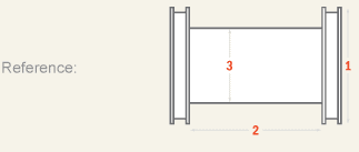
The minimum diameter of the drums is determined by the size of the rope used, and the larger the drums the smaller will be the bending-stresses and the more strength will be available for useful work.
Mr. William Hewitt has shown that, when the diameter of the sheave or drum is 44.5 times the diameter of a 19-wire cast-steel rope, the bending-stresses are 2/3 and the remaining useful strength is 1/3 of the “ maximum safe load ” that the rope will carry. The “ maximum safe load ” is taken as 1/3 the ultimate strength. This is well below the elastic limit of the wire. Thus the available strength is only 1/9 of the ultimate. In order to cut down the bending-stresses so as to leave of the ultimate strength of the rope available for useful work, the sheaves must be about 80 times the diameter of the rope. Other grades of rope require different diameter of drums, as will be seen by studying Tables I. and II.
k represents the bending-stress in pounds, E the modulus of elasticity = 28,500,000, a the aggregate area of the wires in square inches, R the radius of the bend in inches, d the diameter of the individual wires in inches, and C a constant depending on the number of wires in the strand. The values of d and C are, for 19-wire hoisting-rope : d = 1/15 diameter of rope, and C= 45.9.
As an example, required the working-load of a 1-in. cast-steel rope running over a 6-ft. sheave. From Table II. the bending-stress is found to be 9937 lbs., and from Table I. the “ maximum safe stress ” is found to be 22,667 lbs. The difference, 12,730 lbs., is the working-load.
The maximum length of a drum, aside from question of room, is controlled by the allowable fleet-angle, that is, the acute angle included between two lines drawn from the ends of the drum to the head sheave. This angle should not exceed 6°, in order that the rope may lead well on to the head sheave, and so that one rope will not grind or mount the next one in winding onto the drum. It is usual to place the drum far enough back from the head sheave to keep the fleet-angle within the limit; but where it cannot be done, it is necessary to guide the rope onto the head sheave and onto the drum by rollers or sheaves running on vertical spindles. The bisectrix of the fleet-angle should strike the middle of the drum.
Geared engines are made with small cylinders, and the engine proper runs at a speed of 100 to 200 r. p. m. The gearing usually gives a reduction of 1/3 to 1/5 so that the drum revolves at a moderate speed. The small cylinders make the first cost lower than that of a direct-acting engine; but the gearing for large hoists is a serious objection. The main gear has about the same diameter as the drum, so as to keep the pressure on the teeth as low as possible; and hence it has a circumferential speed equal to the speed of hoisting. Gearing, under very favorable conditions, should not run at a speed over 1200 ft. per min., and with the large cast gears and the rough work to which hoisting-engines are subjected, the speed should probably not exceed 900 ft. per min. If the average speed of hoisting is kept at about 2/3 of this maximum, the average speed will not exceed 600 ft. per min. This speed will allow the use of moderate-sized drums and keep the piston- speeds within the limits of good practice.
That gearing is liable to cause trouble and make considerable noise when run at a high speed, has been forcibly impressed on the mind of the writer by his experience in charge of a geared hoister, made by a reliable manufacturer, having cylinders each 18 in. dia. by 24 in. stroke, and two drums, each 7 ft. 6 in. dia. by 5 ft. face, on which three main gears, between 7 and 8 ft. dia., 3 in. pitch, and 9 in. face, were broken inside of nine months. The gears cost about $3000 each, besides the labor of replacing and the loss of 24 hours in changing the old for a new one. The engine was hoisting from a shaft 1000 ft. deep in about 1¼ min. The load of ore was 2½ tons.
Single-drum engines are limited to small outputs per day, or to places where the first cost of the plant is so important as to outweigh the loss in increased operating-expenses. This type of engine has many applications, as for sinking winzes, and for other inside work; also for shaft-sinking, and for working coal-mines on a small scale, where the cost of fuel is small, as waste material is burned. They are largely used in the Joplin, Mo., district, where the hoisting is from vertical shafts 100 ft. deep, the output often only 25 to 50 tons per day, and the ore is raised in buckets without guides, thus keeping the dead weight small, as compared with weight of ore raised. They are not adapted for regular mining work on a large scale, as the work expended in raising the cage, car and rope, each trip, would exceed the work of raising the ore.
Double-drum engines overcome the dead-work of hoisting the ore-carriers by balancing the weight of the cage and car in one compartment against those in the other. They are thus more economical to operate than a single-drum engine, and the cost of installing will probably not be over 50 per cent, greater than for a single-drum engine. The cost of sinking a shaft large enough for two hoisting-compartments and a manway is not much more than that of a shaft with only one hoisting-compartment and a manway; the head buildings must be nearly the same in either case; and the double-drum engine will have smaller cylinders, thus partly offsetting the cost of the second drum.
With cylindrical drums, the ropes in the two compartments, from the cages to the head sheaves, are of constantly varying lengths, and are in balance only when the cages are passing at the center. With double conical drums, the work on the engine is kept constant by giving the cage at the bottom the short leverage of the small end of the drum, and the cage at the top the longer leverage of the large end of the drum.
The Koepe system, as applied to a double-compartment shaft, has a tail-rope passing from the bottom of one cage down and around an idle sheave at the bottom of the shaft, and up to the other cage. Thus the weight of the rope in the two compartments is exactly equal, and the whole hoisting mechanism is in balance at all points of the trip.
The flat-rope system of hoisting attempts to equalize the work on the engine by coiling a rope of rectangular cross-section on a reel, like a surveyor’s linen tape; so that the diameter of the reel increases and the leverage of the load increases as the weight of the constantly shortening rope decreases. Thus the work on the engine is kept constant, when the rate of increase of leverage and decrease of weight are in inverse proportion to each other. The flat ropes, however, are heavier than round ropes of the same strength, are shorter-lived, and cost more at first and for subsequent care. The flat-rope system is very largely used in Montana, and in some other districts which have followed the Montana practice.
The peculiarities of the different types of engines are brought out more fully by the calculation of the size of their cylinders when equipped with the different arrangements of drums.
At the instant of starting, the power in one cylinder acting on the crank, in the top or bottom position, must have a moment equal to or greater than the moment of the unbalanced load pulling from the circumference of the drum. After starting, the other cylinder comes in to accelerate the speed, and the two together are able to hoist the load with steam partially cut off and still maintain the full speed.
Then, for a single-drum, direct-acting engine, Fig. 1, the moment of the load = (W + F) D/2 and the moment of the engine = (P x A x e)L/2. Placing these equal to each other,
If the drum is geared, the engine will make g revolutions to one of the drum, or the leverage of the engine is increased to g times what it would be if directly connected, and the equation becomes
When the weight of the load, size of the drum, and steam pressure are given to determine the size of the cylinders, there are two unknown quantities in the equation, viz.: A and L. Here L can be assumed and the equation solved for A, from which the diameter can be obtained. The usual practice is so to proportion the cylinder that the length of travel is 1¼ to 2½ times the diameter of the piston. If the value of L chosen for trial gives a ratio of stroke to diameter outside of these limits, another value must be taken for L, and another solution made. If the ratio is decided upon first, then the area can be expressed in terms of the stroke, and there is only one unknown quantity in the equation. Thus rd =12L or d = 12L/r (12L being the length of the stroke in inches), and A = π d²/h = π x 144L²/4r²; which substituted in equation 5 , gives
Having obtained the size of cylinders, and knowing the speed of hoisting and size of drum, the speed of the engine can be obtained, and the speed of the piston can be investigated. The speed of hoisting, in feet per min., divided by the circumference in feet, will give the number of revolutions of the drum per minute. If the drum is geared, the engine will make g times as many r. p. m. (revolutions per minute) as the drum, and
As an example, take a double-cylinder engine geared to a single drum, to find the size of cylinders required under the following known conditions : Vertical shaft is 400 ft. deep, cage to be hoisted in one minute; the-weights are, cage 900 lbs., car 600 lbs., ore 1500 lbs., rope 400 lbs.; steam pressure, P, is 60 lbs., e = 0.7, g = 4/1, f = .01 (assumed), D = 4 ft. and L may be taken as 1½ ft. for a trial solution; then,
With double-drum hoisters, where the descending cage and car counterbalance the ascending ones, the general equation 5 still applies, but the value of W and F are changed. Referring to Fig. 2, when a loaded car is to be started from the bottom of the shaft and an empty car is being lowered at the same time,
Or, instead of shortening the stroke, the number of revolutions can be cut down by increasing the diameter of the drum; thus, if D = 9 ft. and L = 4 ft., d will be 27¾ in., the ratio 12L/d = 1.73, and the piston-speed = 566 ft. per min.
Conical drums, as already noted, are intended to equalize the varying load on the engine, due to the change in length and weight of the rope as the cage ascends and descends. As these engines are used where every economy is desirable, they are usually direct-acting and fitted with double drums.
(C + O + Rl) D/2 – (C + Rs) y/2 = moment of the resistance when the load is at the bottom, Fig. 3, position A, and (C+O+Rs)y/2-(C+Rl)D/2 = moment of the resistance when the load is at the top, Fig. 3, position B. The object of the conical drums being to keep this moment constant, these two values must be equal, and
Taking as an example the one used for the engine with double cylindrical drums, depth of shaft 2000 ft. plus 33 1/3 ft. to head sheave above landing, S = 2000 ft. per min., O = 5000 lbs., C = 5000 lbs., Rl = 6100 lbs., Rs. = 100 lbs., D = 7 ft., P = 60 lbs., g = 1, f = .01, e = 0.7, L for trial = 4 ft., to find diameter of cylinder.
There must be a division left between the ropes on a conical drum in order to furnish positive grooves for the rope, so that the large coils cannot slip down over the smaller ones; hence the drum must be longer than those of the cylindrical design, even when the mean diameter of the conical drum is the same as the diameter of a cylindrical one.
In the Koepe system, as applied to a double-compartment shaft, there is a tail-rope of the same weight as the hoisting-rope fastened to the bottom of one of the cages, passed around a sheave in a pit at the bottom of the shaft, and attached to the bottom of the other cage. Then, in whatever position the cages are in the shaft, there is the same weight of rope hanging in each compartment. Thus the entire weight of the hoisting mechanism is in perfect balance at all times, and the engine only has to raise the weight of the ore and overcome the friction of the moving parts. The main rope may be wound on a pair of cylindrical drums, or it can be wrapped back and forth over a pair of multiple-grooved sheaves, as is done in rope drives for many purposes. It is essential that a positive grip is taken on the rope by the driving mechanism, or else its creeping on the driving-sheaves will make the indicators show a false position for the cages, and make accidents of overwinding a great, source of danger.
The conditions in all of the above were the same as used in former examples, except that the diameters of drums are all taken as 9.76 ft., which is the mean diameter of the conical drums. The engines are direct-acting, the shaft has double compartments, and the cages work in balance; C =5000 lbs., O = 5000 lbs., R = 6100 lbs., P = 60 lbs., L = 4 ft., f = .01, e = 0.7, g = 1, S = 2000 ft. The piston-speed is 522 ft. per min. in each case.
The table shows that cylindrical drums are not as economical to operate as either the conical drums or the Koepe system. The conical drums are expensive to make, as the grooves have to be formed spirally and with an increasing radius, and each problem requires a specially-designed drum, so there can be little use made of stock patterns. They are only used where the rope is heavy, and the economy of accurate counter-balancing is clearly indicated, and will offset the extra cost of manufacture.
The Koepe system is a simple method of counter-balancing, and the principle could often be applied to existing plants with cylindrical drums by adding a tail-rope and an idle sheave at the bottom of the shaft, provided there is sufficient sump-room for the sheave and its slide. The objection to the Koepe system, where used without drums, is the liability of the ropes to creep on the sheaves, causing the indicators to give a false record and so increase the danger of overwinding.
Flat ropes of rectangular cross-section are wound on a reel like a tape. When the load starts from the bottom of the shaft the rope winds on the center of the reel, which is of small diameter, and then, as the load rises, the successive layers increase the diameter of the coil on the reel; thus the leverage of the load increases and the weight decreases. If the original diameter of the barrel of the reel and the thickness of the rope are properly chosen, the moment of the resistance will be constant.
From equation 13, knowing t, the value of y can be obtained, or having decided on y, the equation can be solved for t. The minimum diameter of the barrel, D, depends on the thickness of the rope, and can be calculated from Mr. Hewitt’s equation, previously given : k = Ea/2.06 R/d + C in which k= bending-stress in pounds, E = modulus of elasticity = 28,500,000, a = aggregate area of the wire in sq. in., R = radius of the bend in inches, d = diameter of individual wires, and C a constant depending on the number of wires in a strand. With flat rope, d = 1/6 the thickness of the rope, and C = 27.54.
The ideal case would be one in which the work of hoisting was constant at every part of the hoist; but the thickness of the rope may be such that the leverage of the load increases faster or slower than the weight of the load decreases, thus making the work on the engine to vary daring the trip. In such a case, the design must be tested with the cage at various points, to make sure that the engine has sufficient power to handle the loads at the desired speed at all points. For this, equations 9 and 10 may be used.
Generally these hoists are arranged in pairs, so that one cage ascends while the other descends. Then the necessary large diameter of the reel, to make the work constant on the engine, can be found by equation 11, used for conical drums, and the size of the engine from equation 12. After this the thickness of the rope can be found by equation 13.
If the reels cannot be made of such diameter as to make the work of hoisting uniform throughout the trip, with a reasonable thickness of rope, then the case must be considered by itself, and the design must be tested with the cage in positions sufficiently numerous to prove that the engine that will start the load is strong enough to handle it at all points.
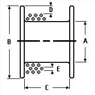
First, a winch works harder the more wraps there are one the drum. This means that when your winch line is mostly spooled up it"s less powerful than when most of the line is played most of the way out. This is because of the increase in distance from the drum to the outer layer of the rope. Lay your arm on a table with 5 lbs in your hand and lift your hand while keeping your elbow on the table. Now tape the 5 lbs to a broomstick and tape the broomstick to your arm. It"ll be much harder with the object of movement much further away. Winch line length is a compromise between ability to reach anchors and power.
Second, more winch cable means that you can jam up your winch more easily. For example, if you do an extreme side pull for an extended period you"ll end up with a pile of cable on the side of the drum. This can damage your cable and damage your winch if you continue to reel in while your cable or rope is jammed.
If you really need more cable length you have three options:Get one of the high-strength, small-diameter winch lines. They are more expensive than regular synthetic but you get more line on the drum in a smaller diameter.
Having built hundreds of hydraulic winches used to tow paraglider pilots aloft, (www.TowMeUp.com look for the hydraulic winch stuff) I can tell you that the loads are enourmous. We use Spectra line which doesn"t stretch much and each layer wound upon the one underneath creates a compound crushing effect. we"ve never crushed the cores of one of our drums even in prototype testing although I"ve seen proably a half dozen other designs fail this way. The typical failure is the core gets greatly compressed which tends to force the mass of line outwards with great force and literally blow the sides of the drum off. Probably the greatest issue is how much tension is applied to the line.
We did use a plastigage type material in earlier testing and found the outward loads imposed on our 26.5 inch drum were in the range of 23,000 pounds plus.
For what it"s worth we make a winch drum 26.5" in diameter, 2" wide with an 8" center solid core reinforced at aroun 14.5" with 24 @ 1" 6061 dowels secured to the drum sides with 5/16" S/S bolts. It works fine with normal applications, but at around 400 pounds of line tension the 5/16" bolts will be drawn to the center of the core where they will fail in shear, and the sides of the drum will blow off.
Your drum looks really nice, but I"m curious how you attach the sides. That seems to be the point of failure more than the crushing of the core. Still, you core seems a wee bit light.
Nylon rope especially stretches a whole bunch. So it has a certain tension applied as it winds on, but it will shrink even tighter just sitting on the spool. If the tension is light I doubt you"ll have any issues. If you are building say a wake board or snowboard winch you may (or may not) have problems. Figure the normal loads you tow with and double or triple it. If the drum stay intact, you"re good to go. The sad part is watching your baby fail during the initial trials.


 8613371530291