
wire rope drum groove design factory
Multi-layer drum systems should use strand- or swage compacted Python® rope constructions having a steel core. The higher fill factor of such rope constructions will offer a greater resistance to crushing and flattening than conventional rope types. This is particularly important for boom hoist ropes on lattice boom cranes at the cross over point from one rope winding to the next.
Cranes equipped with multi-layer drum systems which require rotation-resistant or non-rotating rope are best served with Python Compac® 18 and Compac® 35. To further reduce drum crushing have the rope layers wound onto the drum with about 5-10% of the WLL and avoid that the first layer unspools and re-spools without tension. This would cause a ‘soft’ bottom layer which will flatten the rope.

Changing out crane rope drums or replacing the wire rope is a demanding and time consuming operation for your maintenance team. Based on a study conducted by a technical association that supports the steel industry, the number one reason for replacing rope drums is wear of the grooves.
Wear can make the top surface of the separating land extremely sharp, creating the potential for cutting the wire rope. Wear or corregations in the base of the grooves prevent the wire rope from twisting properly; thus pinching and damaging the rope. The answer to address both of these problems is in the material and heat treatment of your rope drum.
Generally, we recommend grooved drums only. The rope is spooled properly and positively. Depending on the drum/rope diameter relationship helix-grooved drums can be used for up to 3 layers without excessive rope wear. For applications with more than 3 layers (e.g. Mobile cranes) we recommend ‘Lebus’ grooving.
It has to be remembered, however, that rope service life on multiple layer drum systems will always only be a fraction of that compared with single layer helix-grooved drums.
If these values are applied to single layer grooved drums the maximum permissible rope-deflection angle for regular wire rope constructions is 4°. For non rotating /rotation-resistant ropes the maximum permissible deflection angle is 1.5° only.
This invention relates to drums and sheaves used to support wire rope in wire rope systems for lifting heavy loads, such as used in electric mining shovels and walking draglines.
It is important that wire rope be properly supported when it is wound up on a drum if it is not properly supported the wire rope will become mashed. This will result in the breaking of the wires in the central area of the wire rope. Breaking of the wires in the central area of the wire rope can lead to premature failure of the rope because it is not possible to visually inspect rope internal damage. This is an especially dangerous form of wire rope failure. When the wire rope is supported on a drum a spiral groove is placed in the outside periphery of the drum. In the prior art, the shape of the groove was in the form of a half radius of a circle. It was important for the height of the side of the groove to be sufficiently great in order to properly support the wire rope.
This invention provides a device adapted to support a wire rope of known nominal diameter in a system where the fleet angle of rope departure from the device is other than perpendicular to the device, the device comprising a cylindrical body, and a groove around the cylindrical body, the groove having a contour adapted to support the wire rope, the groove contour being such that the wire rope is adapted to be supported through a rope support angle somewhere between 100 degrees and 160 degrees, the rope support angle being the included angle from the nominal rope"s center to each end of the supporting groove contour on each side of the groove, the improvement comprising the groove contour being parabolic in shape over at least about the upper half of the groove contour.
This invention also provides such a device such that the improvement comprises the groove contour having a radial length from the nominal rope center to the contour greater than at the bottom of the groove over at least about the upper half of the groove contour.
This invention also provides a method of making such a device, the method comprising designing the groove contour such that as the wire rope leaves the groove there is a single line of contact between the rope and the respective side of the groove.
Figure 10 is a graphical view of the rope in the "YZ" plane Figure 11 is a plot of the solution to equation 3.30 Figure 12 is a plot of the solution to equation 3.31.
The surface mining industry utilizes large equipment to extract the Earth"s many raw materials: e.g. gold, copper, coal and phosphate. Electric mining shovels and walking draglines are the two main types of machines that are used to move or uncover these raw materials. Both of these types of excavating equipment utilize large quantities of large diameter wire rope.
The most common means of driving a rope to do work is through the use of a drum. One end of the wire rope is attached to the drum and then the drum is rotated which allows the rope to wind onto it. Drums on walking draglines are cylindrical in shape, have flanges on both ends and have a series of grooves for the rope to wind onto.
The grooves provide an excellent rope support which reduces the radial pressure and helps resist crushing, which improves rope life, when compared to an ungrooved wire rope drum. The grooves also provide a path for the rope to follow as it winds onto the drum. This keeps adjacent wraps on the drum from touching one another. The flanges on grooved drums are to provide structural support and may be used to attach the dead end of the wire rope or a bull gear which would provide the torque needed to rotate the drum.
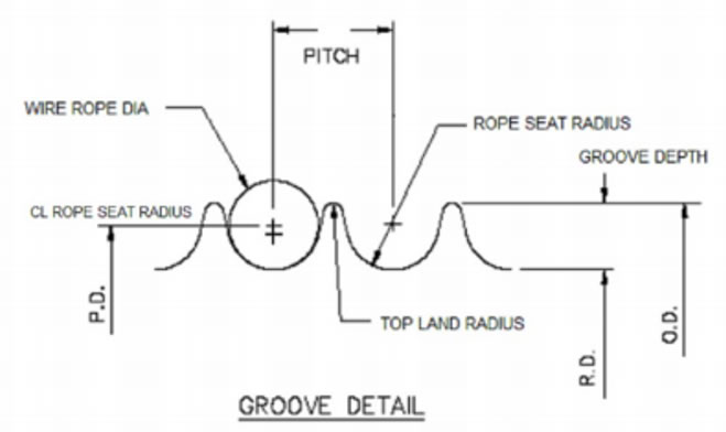
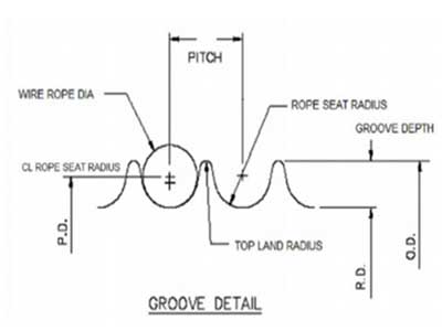
The nomenclature of a generic drum assembly is shown in Figure 1. This illustration greatly exaggerates the rope pitch diameter, drum tread diameter and the rope diameter to better illustrate the groove angle and the rope pitch.
The hoisting drums on walking draglines are grooved and have only a single layer of rope wound onto it. Most of the drums have two ropes which are attached at the drum"s center. Each rope would then wind towards the flanges of the drum.
Drums on walking draglines are typically designed to the minimum recommended tread diameter to minimize the manufacturing and operating costs. Due to the enormous lengths of wire rope required to operate a Walking Dragline the length of the drum (i.e.
T"he sheaves on a Walking Dragline are very similar to a drum. They both have a rope that rides on them and have a groove contour to support the rope. The only real difference is that the sheave has no groove pitch. Figure 2 shows the nomenclature for a generic sheave. This nomenclature will be used throughout this thesis.
Wire rope is one of the most uniform and reliable mechanical products ever invented. If a wire rope is properly used and maintained it can provide an excellent service life. But, if a wire rope were to be abused in shipping, installation or during operation the service life of the rope can and probably will be much less than satisfactory.
Drum diameters are generally referenced as a ratio of the diameter of the sheave or drum (D) with respect to the diameter of the rope (d). This is the D/d ratio. Due to the limited deck space and the cost of manufacturing and operating a large drum on walking draglines and Electric mining shovels the drum D/d ratios are nearly always made to the recommended minimum value of 24.
When drums and sheaves are used in a system, the sheave diameters should be generally larger in diameter than the drum. This is due to the rope only being bent once at the drum and twice at the sheave for each direction of travel. When the rope travels over each sheave the rope will be bent to conform the radius of the sheave as it enters and then bent straight again as it exits the sheave. This is very important on walking draglines since the portion of wire rope operating at the drum may never operate at the boom point sheaves. If the fatigue accumulation is twice as great at the boom point as at the drum, the rope will fail prematurely at the boom point. This phenomenon is simply based on the design.
A fleet angle is the angle between the rope, as it leaves the drum and enters the head sheave, and the plane perpendicular to the axis of the drum. If the angle becomes too great the rope will touch "scrub" onto the groove of the drum or the adjacent wrap on the drum, or both. If a rope is scrubbing, there will be a visible thin band of worn material parallel to the axis of the rope and stretching a long distance along the rope.
This wear is often subject to high pressure, heat and abrasion. If the heat generated by scrubbing raises the local temperature beyond the steels critical temperature, martensite will form on the wires. Martensite is very brittle phase of steel. This will form surface cracks in the wires when the rope is bent around sheaves and drums. Eventually these cracks will propagate through the wire. If no heat is generated the outer wires will simply wear very thin and break.
Scrubbing is a purely geometrical concept. It is the wiping action of the rope onto another rope or the groove contour of the drum. Scrubbing is mainly caused by operating at too high of a fleet angle. Although, scrubbing is also dependent upon the system parameters such as groove contour, rope pitch, drum and rope diameters. When a drum is designed, manufactured and put into service, all of these parameters become fixed. The only geometric parameter that changes is the fleet angle. For every position on a drum there exists a unique fleet angle value.
Every rope which is wound onto a drum is subject to a fleet angle and a groove angle. The fleet angle is the angle the rope needs to follow in order to reach the head sheave as it is wound off a drum. The fleet angle changes for every position along the drum which is defined as the angle between the rope, as it leaves the drum and enters the head sheave, and the plane perpendicular to the axis of the drum. In the prior art, the groove angle, on the other hand, always remains the same for any position on the drum.
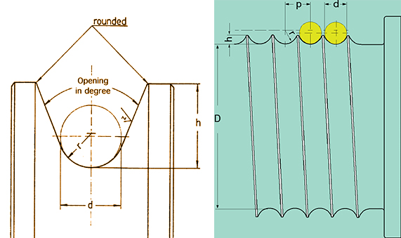
The groove angle, sometimes referred to as lead angle, equals the arc-tangent of the drums groove pitch divided by the circumference at the groove tread diameter.
Groove Angle = arcta~ Gr°°ve Pitch ~ Drum Tread Diameter 7z ( 1.1 ) The fleet angle plus the groove angle is called the total fleet angle. Figure shows a schematic of a sheave and drum system. The drum shown has a right hand lead and a left hand lead grooving with the typical 2 to 2.5 dead wraps (for normal safe operation) and the rest of the grooves are termed active grooves. As shown in Figure 5, the helix angle will either add to or subtract from the groove angle to form the total fleet angle. This is dependent on the direction of grooving. When the fleet angle is large and the drum groove pitch is large the head sheave may need to be shifted to either the right or the left in order to equalize the total fleet angle seen by the drum. If the fleet angles are large, the pitch of the grooves can be increased to eliminate "Rope to Rope"
Scrubbing can be a very serious and costly mode of rope failure. When a rope system experiences severe scrubbing, rope life on that machine will be a fraction of what is expected and the cost of altering the machine while its in operation can cost literally cost millions of dollars.
The "Roebling Wire Rope Handbook" derives a set of close form equations needed to predict the fleet angle at which rope scrubbing will occur based on known values: drum diameter, pitch of grooving and the diameter of wire rope. The following equation defines the total fleet angle that will just cause contact with the preceding wrap on the drum.
Y:= ~d2 - (X- h)2~~5 (1.3) X= h-2 2 Ch2 + 8 d2l (1.4) Where "h" equals the pitch of the grooving , "D" equals the tread diameter of the drum and "d" equals the diameter of the rope.
Using equation 1.2 we can easily find out what angle will cause scrubbing for any given position on the drum. What if we wanted to know what pitch diameter will cause scrubbing based on a known maximum fleet angle; such as 2.000°? With the use of a computer and some iterative math software a program can iterate through these equations and find the exact pitch required. To select a proper rope pitch, the program is used to find the pitch that will just induce scrubbing based on a certain fleet angle, drum and rope diameter. Then, when the rope is at its maximum material condition a small percentage of the ropes diameter is added to the pitch and a gap is defined.
Drum groove scrubbing is when the fleet angle of the rope leaving the drum would be great enough to cause interference between the actual drum profile and the rope; See Figure 3. When scrubbing occurs the outer strands are abrasively worn away in a thin band on only one side of the rope. Groove and rope scrubbing will appear to be the same on the damaged rope, but are caused by two completely different modes of generation.
Drum groove design has been virtually unchanged for many years. The drum groove contour has a specifically defined radius for each given rope diameter which is stated in "Wire Rope Handbook". The maximum allowable fleet angle of the rope is also said to be no greater than 1.50° for smooth drums and 2.00° for grooved drums. The Handbook does state however, that "Fleet angles larger than these suggested limits can cause such problems as ....... the rope rubbing against the flanges of the sheave grooves."
to No reference has been found which gives any indication as to what values design parameters like drum diameter, rope diameter, fleet angle, groove lead and groove radius should have to reduce or eliminate drum groove scrubbing. Now that CNC
machining and computer technologies has evolved so rapidly, the possibility of optimizing the groove contour and pitch to eliminate both "Rope to Rope" and "Rope to Drum"
The initial concept for formulating the governing equations was that, if the rope were to touch the groove, in three dimensional space, then a common point, or set of points, will exist between the rope and the groove. If there are many points, chances are they will form one or more three dimensional continuos curves. When the rope and the groove touch at one point it will be defined as having the coordinates <"Xend","Yend","Zend">.
The next step is to define the equation of the helical rope groove contour as a function of its governing variables in each of the three Cartesian coordinate directions.
Then the equations in the "X", "Y", "Z" directions are defined as being equal to "Xend", "Yend", "Zend" respectively. This equation definition can also be done for the ropes surface. If a point on the rope is to be common to a point on the groove, in order for scrubbing to occur, then the "Xenc~" of the rope is equal to the "Xend" of the groove. This coordinate equalization will be the basis for formulating all the governing relationships.
A single point on the groove contour is then geometrically described. This point is then swept out in the form of a helix in order to simulate the drum groove pitch. This will then define the helix in the "X", "Y" and "Z" directions. Three Cartesian equations a for the rope surface will then be defined. Extensive variable substitution and elimination then yields one equation in two unknowns. Lastly, the final equation is optimized in order to find the absolute minimum value for the drum radius, "Helix Z", that will cause "Rope to Drum" scrubbing to occur.
Once the solution for one single point was found and verified, then a computer program was written to solve for the ideal groove height for many values along the axis of the drum. This multitude of points will generate a curve which represents the complete "Ideal Groove Contour". A solution using the computer program then prints and plots the data that will create the full groove contour.
The governing equation derivation was broken into two main parts. The first part was to symbolically define the groove profile on the drum and the second part was to symbolically define the surface of rope as it leaves the drum. Both of these parts were defined in three dimensional space using the Cartesian coordinate system as a set of closed form equations.
Figure 6 illustrates a helix wound onto a drum, which will take the form of a groove. From this picture, the relationship between the drum axis, global axis and groove contour can easily be seen. Equations defining the position along the helical spiral of the drum were defined in the "X" and "Z" directions. One random point on the contour was picked to start the helix and the helix was swept out through 360° in a left handed positive direction.
1 6 Pitch - h,~ j=x X = Xend (3.1) The distance "Xend" propagates along the drum axis and is directly proportional to the "helix angle". "Xend" is defined as the final solution point in the "X" direction.
The final solution will be where the rope and the groove will just start to intersect. This is where scrubbing will just start to occur. In 360° of rotation, the distance traveled along the drum axis is equal to the pitch of the groove. The "Helix X" term is an arbitrary axial offset in the negative "X" direction. Later on this value will be a predetermined incremental step which will be used to generate the "Ideal Groove Contour".
directions will be required. The loss of one degree of freedom will be compensated for by introducing the general equation of an ellipse. When defining the equations for the rope, an ellipse is created when the cylindrical wire rope is cut with a plane at the fleet angle.
Helix Z cos(8) = Zend (3.2) The same point used in equation 3.1 was also used as the starting point on the groove profile for equation 3.2. The height of "Helix Z" is directly proportional to the cosine of the helix angle ("8"). The "Zend" term will be defined as the final solution in the "Z" direction. Figure 7 shows how "Helix X" relates to "Helix Z". For any value of "Helix X" there exists a "Helix Z" value, such that scrubbing on the drum will initially start. Our goal will be to derive an equation that equates the radial height, "Helix Z", directly to all known quantities.
First, assume that the rope fleets off of the drum in a straight line, it is centered within the drum"s radius and that the rope returns to a cylindrical shape very shortly after leaving the drums surface. The global coordinate axis will be centered on the axis of the drum with the centerline of the rope passing through the "Z" axis and the axis of the rope running directly down the "Y" axis while at a zero degree fleet angle. This is the same global position as stated above.
The fleet angle is the angle at which the rope leaves the drum. This fleet angle is zero only at when the rope leaves the drum exactly perpendicular to the "X Z"
plane. As the rope winds onto the drum the fleet angle will either increase of decrease depending on the position of the head sheave. For a single layer hoisting drum, the maximum fleet angle usually occurs when the drum is completely full. This is when the rope has wound onto the last and final wrap available on the drum. For our analysis, a random position on the drum was chosen to be the global axis system. The "~" axis of this system passes through the center of the groove and the rope. The fleet angle will be positive when the rope rotates about the positive "Z" axis. Figure 8 shows the basic geometry of a rope as it leaves the drum when subjected to a fleet angle.
Figure 9 shows how the cutting plane creates an ellipse as it intersects the rope at a fleet angle. Remember, the axis of the rope only rotates about the "Z" axis and remains in a plane parallel to the "X Y" plane. Figure 10 shows a view looking in the "YZ" plane which shows the relationship of the helical roll angle, "Yend", and the solution point "P"
direction is the distance to the center of the ellipse minus the distance back to the contour of the ellipse at the solution point "P". This is simply one half the drum rope pitch diameter "DRPD" minus the "Y Ellipse". This is shown below as equation 3.8.
.5 1 DRPD - 1 - x rl 2 - Zend 2 r2 2 (3.13) Equations 3.9, 3.11 and 3.13 are the three final equations which define the final solution on the surface of the rope. The next step is to define the values for "rl" and "r2". The quantity "rl" is the minor axis of the ellipse, which is defined as the drum rope radius "DRR" since the axis of the rope is parallel to the "X Y" plane.
rl = DRR (3.14) The quantity "r2" is the major axis of the ellipse which is defined as the drum rope radius divided by the Cosine of the fleet angle "a". The "intersecting plane" cuts the cylindrical rope at precisely that angle.
(3.17) is z22+x2cos(2)2=1 DRR DRR (3.18) Equations 3.1 and 3.2 above are restated here for the definition of the groove helix geometry so that the final five equations are all on one page.
+ ~.25 82 Fitch2 - 8 Filch Helix h"II+Helix X2 II2~ cos(ec)2 + ~ -DRR2 + . 25 DRPD2~ II2 (3.25) When the value of this equation is equal to or less than zero scrubbing is taking place. Our intent will be evaluate where this equation equals zero. This is where the groove contour and the rope contour will be touching.
as II2- cos(o~)2IZ2+cos(6)2 cos(c~c) II2 (3.27) bh ~ -2 Helix X II2 + 8 Pitch IZ~ cos( cx) sin( 8) sin( c~c) - DRPD cos( 8) II2 (3.28) cc = ~.25 62 Pyitch2 - APitch Helix XII+Helix X2 II2~ cos(a)2 + { -DRR2 + .25 DRPD2~ II2 (3.29) If we substitute "aa", "bb" and "cc" into equation 3.26 we will get one equation in one unknown "8". There are two roots, the negative root represents the intersection at the bottom of the rope and the positive root represents the intersection at the top of the rope. Due to geometry, only the negative solution is of interest to us.
In looking at Figure 11 we can see the vertical axis is "Helix Z" which is the drum radius. Therefore by inspection, the lower curves represents the underside of the rope, which is where scrubbing is likely to occur. The upper curve represents the top side of the rope, which is meaningless for groove scrubbing.
(3.31) Where "Pitch" = Pitch of the drum, "DRR" = Drum rope radius, "DRPD" = Drum rope pitch diameter, "a" = Fleet angle and "8" = Roll angle of the helix.
In many ways drums and sheaves are the same. They both have fleet angles, groove radii and D/d diameter ratios. The only big difference is that a sheave has only one straight groove and therefore has no "Pitch". When the "Pitch" in equations 3.25 and 3.31 is set equal to zero they become simplified to equations 3.32 and 3.33 respectively.
The solution for the ideal drum groove contour was presented above and it turns out that final solution, equation 3.25 and equation 3.31, is extremely nonlinear in "8".
Drum groove scrubbing will be evaluated at every value of "Helix X" along the axis of the drum up to one half of the rope pitch. Beyond that point, the solution would be meaningless; the start of the neighboring groove will obviously lie beyond that point.
The value of "Helix X" can be placed into a list and be incremented by very small amounts up to a value of half the rope pitch. Then the value of "Helix Z" can be solved for each and every value of "Helix X" by utilizing equations 3.25 and 3.31.
Since the only unknown variable in equation 3.31 is "A", TkSolver can then iterate until a solution is found. TkSolver will then utilize that value of "0" in equation 3.25 and solve for "Helix Z". The drum radii that will just allow scrubbing to occur is the value "Helix Z".
Tk-Solver provides the solution that at exactly 2.500" along the axis of the drum, for these system constants, the roll angle of the helix is "0" = 2.972°
and the ideal drum The rope support angle is defined as the angle the rope is supported within the drums groove if the rope were under high tension. The rope will flatten (elliptical) into the groove contour. If a line from the end of support is drawn through the theoretical center of the rope and a line is drawn from the other end of support through the theoretical center of the rope, then the angle included between these two lines is defined as the rope support angle. Figure 1 illustrates exactly how to measure the rope support angle.
If the rope support angle is too small then the rope will be lacking support and will then be flattened and elliptical shaped. This will cause the rope to fail by interstitial strand penning and nicking which will eventually cause the internal wires fail prematurely. This is one of the most dangerous forms of wire failure; since it cannot be found by a simple visual inspection. The internal broken wires are only noticed after they have worked their way to the outside of the rope.
If the rope support angle is too great, then the rope will scrub against the groove and cause "Rope to Drum " scrubbing. The rope will actually scrub against the groove contour, even when the fleet angle may be very low. A wire rope has an increased risk of "Drum to Groove" scrubbing when the drum diameter, pitch or the fleet angle are too large. Figure 3 shows "Rope to Drum" and "Rope to Rope" scrubbing. The question to ask is; What groove contour will provide adequate rope support and at the same time prevent or minimize groove scrubbing?
There are three specific parameters required to design a new groove. They are groove pitch, groove radius and rope support angle. There are several parameters that are set by the surrounding envirorunent and machinery. These parameters are usually defined early in the design process which usually occur long before a designer actually designs the drum groove contour. Some of these parameters are rope diameter, drum capacity (which affects the drum tread diameter and drum length) and the sheave and drum placement (which affects the maximum operating fleet angle). When these parameters are being designed, the designer needs to foresee the possible future consequences of fixing their values.
The first to be defined is the nominal rope diameter. The rope diameter is usually chosen very early in the design. It is based on the rated suspended load the Walking Dragline is expected to hoist or drag. The rope diameter typically ranges from 2.00" to 6.00" in diameter. The ropes are manufactured to a tolerance to +0% to +$% of nominal rope diameter. For this example, a nominal rope diameter of 4.00" will be used.
The second issue is drum capacity and D/d Ratio. Drum capacity is a function of the number of wraps wrapped on the drum and the drums tread diameter. The drum diameter is usually set to the minimum recommended diameter for the wire rope being used. The drum ratio typically used is a D/d equal to 24.
The maximum operating fleet angle is the last of the three predefined variables the designer needs to contend with. The maximum fleet angle is directly affected by where the sheaves and the drum are placed on a machine. The maximum operating fleet angle for a grooved drum is typically 2.00°. The designer needs to consider the placement of the drum and sheaves such that the fleet angle will never exceed this value.
For this example, the rope diameter will be 4.00", the drum tread diameter will be 24*4.00" _ 96.00" and the maximum allowable fleet angle will be set at 2.00°.
As stated above, there are three specific parameters a designer has control over when designing a new groove contour. They are groove pitch, groove radius and rope support angle. The groove pitch or lead of the rope is chosen in order to prevent rope to rope scrubbing, as described earlier. The equations initially stated above predict the exact total fleet angle at which "Rope to Rope" scrubbing will occur. Using this relationship, the equations 1.2, 1.3 and 1.4 are programmed into Tk-Solver and its iterative equation solver is used to find the value of any one variable in terms of all the others. More specifically, Tk-Solver is used to find the groove ip"tch required in order to just cause "Rope to Rope" scrubbing based on a known drum tread diameter, true rope diameter and a maximum fleet angle.
Tk-Solver will iterate through these equations by simply giving an initial guess for the rope pitch. This example has a maximum fleet angle of 2.000°, a drum diameter of 96.000" and a nominal rope diameter of 4.000" which may be manufactured at +S%
larger than standard, LE. 4.200". Tk-Solver iterates through the set of equations until a convergence is found. The ideal groove pitch is 4.5838". This is based on a rope that is manufactured at a S% oversize condition. If the designer wanted added security that scrubbing will not occur, they can simply add a small amount to the pitch. In this example, the groove pitch may be rounded up to 4.600". This will leave a small gap of .0162" even when the largest possible rope size is placed on the grooves and the rope is operating at the maximum fleet angle. In this particular example, the 4.600"
and 10% larger than the nominal rope diameter. For this example, 2.139" is used as the groove radius. This value corresponds to 6.5% larger than nominal rope diameter.
When the wire rope deforms into the groove radius, it will flatten and become oval shaped. Because of this, the rope needs to be supported on its circumference by some specified angle. Many sources specify a rope support angle which can vary from 120° to 1 SO°. Most sources recommend 135° for adequate rope support. For this particular example, a rope support angle of 135° will be used.
The last and final step is to define the drum groove depth. The depth of the groove is the distance from the bottom of the groove (D/2) to the outside diameter of the drum. At this point the designer has already defined the pitch, groove radius and the rope support angle. This is all that is required in order to define the groove depth is to create the circle that is tangent to both of the groove radii and the two 135°
This will define the "Cap" radius between two adjacent grooves. In Figure 13 there is a layout of the standard drum groove and the cap radius we have just defined.
In conclusion, the standard drum groove design procedure for a 4.000" nominal rope diameter with a maximum operating fleet angle of 2.000° and a tread diameter of 96.000", will have a groove radius of 2.139", cap radius of .351", drum outside diameter of 99.074" and a rope support angle of 135°.
The sheave design example is very similar to the drum. The only difference is that groove has no pitch and the depth of the groove is increased significantly in order to prevent the rope from bouncing out of the sheave. The only additional parameter is the "Throat Angle"; see Figure 2. The throat angle is nothing more than 180° minus the rope support angle. For our 4.000" nominal rope diameter example, the throat angle will be 45°. The groove radius and the tread diameter will remain the same, 96.000" and 2.139" respectively.
Depending on the application, the groove depth should be 1.5 to 2.5 rope diameters. Past experience of specific applications will be the best judge. If the wire rope experiences sudden changes in tension, shock load, it may jump out of a sheave.
Some applications will never experience shock loading and therefore have a groove depth as small as a standard drum. Figure 14, illustrates the standard sheave groove design with a groove depth of 1.50 times the nominal rope diameter.
The fleet angle for a sheave, just like a drum, should not exceed 2.000°. Since there is no pitch, there is no need to consider anything else. For a sheave with a nominal 4.000" rope diameter and a fleet angle of 2.000° and a tread diameter of 96.000", the sheaves groove radius will be 2.139", throat angle will be 45°, groove depth will be 6.000", rope support angle will be 135° and the outside diameter will be 108.000".
The existing groove design procedure has several similarities to the newly proposed groove design procedure. Both of these procedures have the same parameters which are defined by the surrounding environment and machinery; such as a maximum operating fleet angle, minimum drum tread diameter and nominal rope diameter.
The pitch design procedure explained above will be exactly the same in the ideal contour design procedure. The only radical alteration to the existing design procedure will be to redefine the groove radius.
When the rope groove radius is in the form of a true radius, it does not take into account the effects of "Rope to Drum" scrubbing. The equations derived above define the "Ideal Groove Contour" that will just eliminate scrubbing for any drum or sheave.
The ideal drum groove design example will incorporate many similar parameters that were previously defined above. Here, the drum tread diameter was 96.000", maximum fleet angle was 2.000° and the nominal rope diameter was 4.000". The ideal pitch that will eliminate "Rope to Rope" scrubbing was defined as 4.600". For consistence, the 135° rope support angle will also be kept the same.
The only change will be in the way the rope"s supporting radius is defined. The rope groove radius is defined as a parabolic shape ( Equation 3.25 and Equation 3.31 ). By altering the shape of the groove and keeping all of the other parameters the same, the "Cap" radius and Drum outside diameter will both be forced to change.
In order to solve for the ideal groove contour, only four parameters are required, drum tread diameter, actual rope diameter, maximum operating fleet angle and rope groove pitch. All of these parameters are defined in the existing groove design procedure stated above. A TkSolver program was written to solve for the ideal drum radius required to eliminate "Rope to Drum" groove scrubbing. The program will utilize "Newton"s Method" for finding roots and solve for "A" and "Helix Z" by starting with only an initial guess. The program is set up to solve for one single solution.
This solution will be located along the drum axis at a "Helix X" value of 1.000". The solution converges to a final value of "Helix 2" equal to 48.249" and a helix roll angle "0"of 1.518°.
This TkSolver program can solve for an ideal contour at any point along the drums axis (.01, .02, .03... 2.01, 2.02......) up to half of the groove pitch.
i , y so ve or a the positions specified. 1 0.000 48.000 2 0.100 48.002 This data was then drawn in CATIA along 3 0.200 48.009 with 4 0.300 48.021 all of the other pertinent groove and 5 0.400 48.038 drum parameters.
11 1.000 48.249 function within CATIA. The resulting 12 1.100 48.305 spline represents 13 1.200 48.369 is a parabola that defines the "Ideal 14 1.300 48.440 Drum Groove 15 1.400 48.521 Contour". 16 1.500 48.611 17 1.600 48.712 Once the contour has been created, then 1 g 1.700 48.827 the entire la 19 1.800 48.958 out of the drum rofile can be com leted y 20 1.900 49.109 p p .
Figure 15 is the final drum design using21 2.000 49.284 the newly 22 2.100 49.489 proposed design methods. Due to the new 23 2.200 49.733 groove ( 24 ~ 2.300 50.024 contour, a new "Cap" radius and new drum outside Ideal Drum Groove Contour Data diameter have been defined. The 135° rope support angle, 4.600" pitch and the 96.000"
The ideal sheave contour will have exactly the same characteristics as the standard sheave groove contour. The tread diameter, outside diameter and throat angle will all remain the same. The groove support radius will be similar to the ideal contour defined above. The main difference is that a sheave has no pitch and therefore has less of a possibility of having "Groove Scrubbing".
The output of the ideal groove contour program is then computed for when the ip tch is set equal to zero. This particular solution was located along the drum axis at a "Helix X" value of 1.000". The radial height "Helix Z" that is associated with that value is 48.258". Again, Tk-Solver will solve for all of the required points and CATIA was used to connect and analyze the data.
Figure 17 illustrates the ideal contour superimposed onto the standard groove contour. Note that the ideal contour never penetrates the standard contour.
Lines are then created which are parallel to the 45° throat angle and are tangent to the "Ideal Groove Contour". This tangency condition occurs at 140.7°, which is slightly above the standard 135°. This illustrates that there will be an .018" gap between the ideal and standard groove contours. This means that scrubbing will not be a problem for this particular design. In this example, we would typically adopt all of the "Standard Design"
This sheave will have a nominal rope diameter of 4.00", maximum operating fleet angle of 2.000° and a tread diameter of 96.000". The sheaves groove radius will be 2.139", throat angle will be 45°, groove depth will be 6.000", rope support angle will be 135° and the outside diameter will be 108.000".
The standard and ideal groove contours are very similar in shape. The standard groove has a true radius supporting the rope and the ideal contour has a parabola supporting the rope. The difference between these two geometric shapes is closely examined below. All of the other groove geometry (rope support angle, groove pitch, tread diameter) remains the same.
In order to compare the drum groove geometry, we need to define a common reference point for all of the groove shapes. The common datum is located at the center of the rope when the rope is manufactured at it"s nominal diameter. The groove contour comparison will be based on the distance from the center of this rope to all of the proposed contours.
over nominal rope diameter curves represent the recommended maximum and minimum values for the groove radius which is stated in the Wire Rope Users Manual 3rd Edition.
The rope support angle is plotted on the abscissa axis from the centerline of the rope and towards the right. This is the positive "Helix X" direction which was defined above.
The total rope support angle is twice that stated in figure 18. The two vertical reference lines define the minimum and maximum rope support angles recommended by several sources.
The radius of the rope does not change as the rope support angle increases. The distance from the center of the nominal rope diameter to the 6% and 10% are parabolic in nature. This is because the circles are not concentric. All of the circles are tangent to the tread diameter and therefore the centerlines are all shifted vertically by the change in rope radius.
If the groove radius was to be manufactured at 10% over the nominal rope diameter the "Drum Groove" scrubbing will only occur at a rope support angle of about 140° and greater, see Figure 18. If the groove support angle was to be only 135° then the rope will not scrub at all. At first, this may appear satisfactory, but when the rope is allowed too much freedom to deform to the shape of the groove, then the internal fatigue damage will greatly reduce the life of the wire rope.
If the groove was to be manufactured to 6% over the nominal rope diameter, then scrubbing will exist for nearly all rope support angles. At this small 6%
groove radius, the amount of deflection due to scrubbing interference will have a dramatic affect on the life of the rope. The rope will not only scrub severely, it may also not allow enough room for the individual wires to shift positions as the rope is wound onto the drum. This will pinch the rope and will cause accelerated cyclic fatigue.
The goal is to allow minimum movement of the rope which will still allow the individual wires to relocate as the rope is bent around a drum and to prevent "Rope to Drum" drum groove scrubbing.
In Figure 18 the "Ideal Groove Contour" is also plotted. This groove contour is slightly greater than the 6% curve up to about 40°. After that point, the amount of scrubbing increases greatly. If the groove was manufactured at this ideal contoured shape, the rope will not scrub on the drum, at all.
Above, the groove radius was chosen to be 2.139". This is the recommended radius stated in the Wire rope Handbook 2nd Edition. If this curve was plotted on the same graph, the relative distance between it and the ideal contour could then be measured. These measurements are shown in the table below. Notice that the 2.139"
Beyond that value, the deviation increases exponentially. If the rope support angle was to be only 135° we will need to modify the recommended radius by .028". If we wanted a GrooveHalf StandardTrue Deviation SupportSupportDesign Ideal From Angle Angle ProcedureContourStandard [degrees][degrees](inches][inches][inches]
When the rope is being wound onto a drum and if the drum has a 135° of rope support angle, then the rope will need to be deflected by .028" in order for the rope to pass.
When the rope is under a high tension, the actual pressure on the individual wires can become extreme. This will cause severe abrasive wear and burning of the rope, which may cause the formation martensite on the surface of the wires, which will also greatly accelerate the cyclic fatigue and initiate crack propagation.
In various embodiments of the invention, the groove contour may vary from side to side as the fleet angle changes from one side of the groove to the other, or from groove to groove. In most embodiments however, a single groove contour will be used over the entire drum.

Winch drum, hoist drum, and crane drum for sale from Dongqi Hoist and Crane, the manufacturer and supplier of types of cranes, electric hoists, winches, at good price. Dongqi offer custom winch drum design, hoist drum design, and crane drum design for your need. Which do you need, winch drum hoist drum or crane drum?
The biggest advantage of the Polygonal line drum is that it maximally protects the wire ropes that are wound on the reel, minimizing the point of contact between the strands, thereby extending the service life of the wire rope.
Dongqi Hoist and Crane can design types of drums for hoist, winch, and crane. In the following, the winch drum, hoist drum, and crane drum in Dongqi"s electric winch, electric hoist, and types of cranes are presented for your reference.
Dongqi electric drum winch shop mainly offering you the Engineering / construction winch, Marine Winch and Mine Winch with the capacity of 1-800 ton, which can be customize to you application environment.
Dongqi Hoist and Crane has types of electric drum winch for you, such as,small electric drum winch, light duty winch, and heavy duty winch, rope electric drum winch, cable electric drum winch, hoist winch, mining industrial electric drum winch and other types of electric drum winch,etc. In the following, the hot electric wicnh will be presented for your reference, inculding, Variable speed electric drum winch for sale,Planetary electric drum winch for sale,Friction electric drum winch for sale,High speed winch for sale,Low speed electric drum winch for sale,Double drum electric drum winch for sale,Piling electric drum winch for sale, and Heavy duty winch, etc.
As a hoist manufacturer and supplier, Dongqi Hoist and Crane offers types of electric hoists for customers, mainly electric chain hoist and rope drum hoist, etc. Dongqi rope drum hoists offering includes single / double speed hoist, low headroom hoist, explosion proof hoist, safety hoist, etc. The hot rope drum hoists are presented for your referencef in the following:
Wire rope drum is a part of crane lifting mechanism which is used to full in, entwine, and store wire rope. The Wire rope drum is consisted of drum shaft, flange type annular gear, drum hub, bearings, bearing pedestal, etc. Every part of Wire rope drum is engineered and manufactured to meet the operational and safety requirements of industrial crane applications.
Wire rope drum is usually made of cast iron. However, on special occasions or based on your special requirements, Wire rope drum can directly weld with cast steel or steel plate. Customized Wire rope drum is available from Dongqi Hoist and Crane.
Winch drum, hoist drum, and crane drum for sale from Dongqi Hoist and Crane, the manufacturer and supplier of types of cranes, electric hoists, winches, at good price. Dongqi offer custom winch drum design, hoist drum design, and crane drum design for your need. Which do you need, winch drum, hoist drum or crane drum?

The primary purpose of the LeBus Spooling System is to spool wire rope or cable onto hoisting drums in a true and correct manner. In most spooling operations, you never encounter severe spooling problems when spooling only one layer of cable on your drum. In all other cases, your trouble will begin when you start the second layer and from there on up through your last layer.
The LeBus System is the only system on the market that can eliminate the 360o continuous cross winding of the cable as found on smooth drums. The LeBus System cuts down the cross winding to approximately 20% of the circumference of the drum while 80% of the wraps are parallel with the flanges. In view of this pattern, each layer of wire rope then becomes the groove pattern for each succeeding layer.
The LeBus pattern puts the same number of coils on each layer thereby eliminating the "cutting-in" of the cable. This severe scrubbing action can cause the wire rope to fail prematurely. The LeBus System is the only known method that can accomplish this feat. Therefore it creates a much safer environment. Another benefit is increased wire rope life. Since the wire is not "cutting in" and scrubbing on itself, the true pyramid stacking pattern promotes long rope life.
Flexibility is an asset that cannot be overlooked. The sleeve can be added to the smooth drum either during original manufacturing or after the hoist is in the field.
Rope diameter is specified by the user and is generally given in the equipment manufacturer’s instruction manual accompanying the machine on which the rope is to be used.
Rope diameters are determined by measuring the circle that just touches the extreme outer limits of the strands— that is, the greatest dimension that can be measured with a pair of parallel-jawed calipers or machinist’s caliper square. A mistake could be made by measuring the smaller dimension.
The right way to unreel.To unreel wire rope from a heavy reel, place a shaft through the center and jack up the reel far enough to clear the floor and revolve easily. One person holds the end of the rope and walks a straight line away from the reel, taking the wire rope off the top of the reel. A second person regulates the speed of the turning reel by holding a wood block against the flange as a brake, taking care to keep slack from developing on the reel, as this can easily cause a kink in the rope. Lightweight reels can be properly unreeled using a vertical shaft; the same care should be taken to keep the rope taut.
The wrong way to unreel.If a reel of wire rope is laid on its flange with its axis vertical to the floor and the rope unreeled by throwing off the turns, spirals will occur and kinks are likely to form in the rope. Wire rope always should be handled in a way that neither twists nor unlays it. If handled in a careless manner, reverse bends and kinks can easily occur.
The right way to uncoil.There is only one correct way to uncoil wire rope. One person must hold the end of the rope while a second person rolls the coil along the floor, backing away. The rope is allowed to uncoil naturally with the lay, without spiraling or twisting. Always uncoil wire rope as shown.
The wrong way to uncoil.If a coil of wire rope is laid flat on the floor and uncoiled by pulling it straight off, spirals will occur and kinking is likely. Torsions are put into the rope by every loop that is pulled off, and the rope becomes twisted and unmanageable. Also, wire rope cannot be uncoiled like hemp rope. Pulling one end through the middle of the coil will only result in kinking.
Great stress has been placed on the care that should be taken to avoid kinks in wire rope. Kinks are places where the rope has been unintentionally bent to a permanent set. This happens where loops are pulled through by tension on the rope until the diameter of the loop is only a few inches. They also are caused by bending a rope around a sheave having too severe a radius. Wires in the strands at the kink are permanently damagedand will not give normal service, even after apparent “re-straightening.”
When wire rope is wound onto a sheave or drum, it should bend in the manner in which it was originally wound. This will avoid causing a reverse bend in the rope. Always wind wire rope from the top of the one reel onto the top of the other.Also acceptable, but less so, is re-reeling from the bottom of one reel to the bottom of another. Re-reeling also may be done with reels having their shafts vertical, but extreme care must be taken to ensure that the rope always remains taut. It should never be allowed to drop below the lower flange of the reel. A reel resting on the floor with its axis horizontal may also be rolled along the floor to unreel the rope.
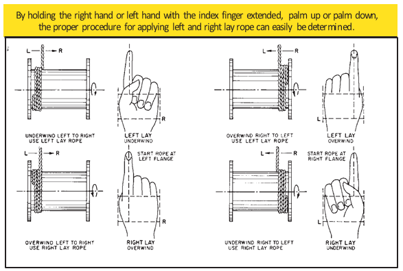
Wire rope should be attached at the correct location on a flat or smooth-faced drum, so that the rope will spool evenly, with the turns lying snugly against each other in even layers. If wire rope is wound on a smooth-face drum in the wrong direction, the turns in the first layer of rope will tend to spread apart on the drum. This results in the second layer of rope wedging between the open coils, crushing and flattening the rope as successive layers are spooled.
A simple method of determining how a wire rope should be started on a drum. The observer stands behind the drum, with the rope coming towards him. Using the right hand for right-lay wire rope, and the left hand for left lay wire rope, the clenched fist denotes the drum, the extended index finger the oncoming rope.
Clips are usually spaced about six wire rope diameters apart to give adequate holding power. They should be tightened before the rope is placed under tension. After the load is placed on the rope, tighten the clips again to take care of any lessening in rope diameter caused by tension of the load. A wire rope thimble should be used in the eye of the loop to prevent kinking.
U-bolt Clips.There is only one correct method for attaching U-bolt clips to wire rope ends, as shown in TheRightWayimage below. The base of the clip bears on the live end of the rope; the “U” of the bolt bears on the dead end.
Compare this with the incorrect methods. Five of the six clips shown are incorrectly attached—only the center clip in the top view is correct. When the “U” of the clip bears on the live end of the rope, there is a possibility of the rope being cut or kinked, with subsequent failure.
Proper seizing and cutting operations are not difficult to perform, and they ensure that the wire rope will meet the user’s performance expectations. Proper seizings must be applied on both sides of the place where the cut is to be made. In a wire rope, carelessly or inadequately seized ends may become distorted and flattened, and the strands may loosen. Subsequently, when the rope is operated, there may be an uneven distribution of loads to the strands; a condition that will significantly shorten the life of the rope.
Either of the following seizing methods is acceptable. Method No. 1 is usually used on wire ropes over one inch in diameter. Method No. 2 applies to ropes one inch and under.
Method No. 1: Place one end of the seizing wire in the valley between two strands. Then turn its long end at right angles to the rope and closely and tightly wind the wire back over itself and the rope until the proper length of seizing has been applied. Twist the two ends of the wire together, and by alternately pulling and twisting, draw the seizing tight.
The Seizing Wire. The seizing wire should be soft or annealed wire or strand. Seizing wire diameter and the length of the seize will depend on the diameter of the wire rope. The length of the seizing should never be less than the diameter of the rope being seized.
Proper end seizing while cutting and installing, particularly on rotation-resistant ropes, is critical. Failure to adhere to simple precautionary measures may cause core slippage and loose strands, resulting in serious rope damage. Refer to the table below ("Suggested Seizing Wire Diameters") for established guidelines. If core protrusion occurs beyond the outer strands, or core retraction within the outer strands, cut the rope flush to allow for proper seizing of both the core and outer strands.
The majority of wire rope problems occurring during operation actually begin during installation, when the rope is at its greatest risk of being damaged. Proper installation procedures are vital in the protection and performance of wire rope products.
Until the rope is installed it should be stored on a rack, pallet or reel stand in a dry, well-ventilated storage shed or building. Tightly sealed and unheated structures should be avoided as condensation between rope strands may occur and cause corrosion problems. If site conditions demand outside storage, cover the rope with waterproof material and place the reel or coil on a support platform to keep it from coming directly in contact with the ground.
While lubrication is applied during the manufacturing process, the wire rope must still be protected by additional lubrication once it is installed. Lubricants will dry out over a period of time and corrosion from the elements will occur unless measures are taken to prevent this from happening. When the machine becomes idle for a period of time, apply a protective coating of lubricant to the wire rope. Moisture (dew, rain, and snow) trapped between strands and wires will create corrosion if the rope is unprotected. Also apply lubricant to each layer of wire rope on a drum because moisture trapped between layers will increase the likelihood of corrosion.
Always use the nominal diameter as specified by the equipment manufacturer. Using a smaller diameter rope will cause increased stresses on the rope and the probability of a critical failure is increased if the rated breaking strength does not match that of the specified diameter. Using a larger diameter rope leads to shorter service life as the rope is pinched in the sheave and drum grooves which were originally designed for a smaller diameter rope. Just as using a different diameter rope can create performance problems, so can the use of an excessively undersized or oversized rope.
Measure the wire rope using a parallel-jawed caliper as discussed in Measuring Rope Diameter at the top of this page. If the rope is the wrong size or outside the recommended tolerance, return the rope to the wire rope supplier. It is never recommended nor permitted by federal standards to operate cranes with the incorrect rope diameter. Doing so will affect the safety factor or reduce service life and damage the sheaves and drum. Note that in a grooved drum application, the pitch of the groove may be designed for the rope’s nominal diameter and not the actual diameter as permitted by federal standards.
Wire rope can be permanently damaged by improper unreeling or uncoiling practices. The majority of wire rope performance problems start here.Improper unreeling practices lead to premature rope replacement, hoisting problems and rope failure.
Place the payout reel as far away from the boom tip as is practical, moving away from the crane chassis. Never place the payout reel closer to the crane chassis than the boom point sheave. Doing so may introduce a reverse bend into the rope and cause spooling problems. Follow the guidelines highlighted under Unreeling and Uncoiling and Drum Winding. Take care to determine whether the wire rope will wind over or under the drum before proceeding. If the wire rope supplier secured the end of the rope to the reel by driving a nail through the strands, ask that in the future a U-bolt or other nondestructive tie-down method be used; nails used in this manner damage the rope.
Take extra precaution when installing lang lay, rotation-resistant, flattened strand or compacted ropes. Loss of twist must be avoided to prevent the strands from becoming loosened, causing looped wire problems.
The end of the rope must be securely and evenly attached to the drum anchorage point by the method recommended by the equipment manufacturer. Depending on the crane’s regulatory requirements, at least two to three wraps must remain on the drum as dead wraps when the rope is unwound during normal operations. Locate the dead end rope anchorage point on the drum in relation to the direction of the lay of the rope. Do not use an anchorage point that does not correspond with the rope lay. Mismatching rope lay and anchorage point will cause the wraps to spread apart from each other and allow the rope to cross over on the drum. Very gappy winding will occur resulting in crushing damage in multilayer applications.
Back tension must be continually applied to the payout reel and the crewman installing the rope must proceed at a slow and steady pace whether the drum is smooth or grooved.Regardless of the benefits of a grooved drum, tension must be applied to ensure proper spooling. An improperly installed rope on a grooved drum will wear just as quickly as an improperly installed rope on a smooth drum. If a wire rope is poorly wound and as a result jumps the grooves, it will be crushed and cut under operating load conditions where it crosses the grooves.
Every wrap on the first or foundation layer must be installed very tightly and be without gaps. Careless winding results in poor spooling and will eventually lead to short service life. The following layers of rope must lay in the grooves formed between adjacent turns of the preceding layer of rope. If any type of overwind or cross-winding occurs at this stage of installation and is not corrected immediately, poor spooling and crushing damage will occur.
On a multilayer spooling drum be sure that the last layer remains at least two rope diameters below the drum flange top. Do not use a longer length than is required because the excess wire rope will cause unnecessary crushing and may jump the flange. Loose wraps that occur at any time must be corrected immediately to prevent catastrophic rope failure.
The use of a mallet is acceptable to ensure tight wraps, however a steel-faced mallet should be covered with plastic or rubber to prevent damage to the rope wires and strands.
Rotation-resistant ropes of all constructions require extra care in handling to prevent rope damage during installation. The lay length of a rotation-resistant rope must not be disturbed during the various stages of installation. By introducing twist or torque into the rope, core slippage may occur—the outer strands become shorter in length, the core slips and protrudes from the rope. In this condition the outer strands become over- loaded because the core is no longer taking its designed share of the load. Conversely, when torque is removed from a rotation-resistant rope core slippage can also occur. The outer strands become longer and the inner layers or core become overloaded, reducing service life and causing rope failure.
The plain end of a wire rope must be properly secured. If the entire cross section of the rope is not firmly secured, core slippage may occur, causing the core to pull inside the rope’s end and allowing it to protrude elsewhere, either through the outer strands (popped core) or out the other end of the line. The outer layer of the outside strands may also become overloaded as there is no complete core-to-strand support.
Secure the ends of the rope with either seizing or welding methods as recommended under Seizing Wire Rope. It is imperative that the ends be held together tightly and uniformly throughout the entire installation procedure, including attaching the end through the wedge socket and the drum dead end wedge
When installing a new line, connect the old line to the new line by using a swivel-equipped cable snake or Chinese finger securely attached to the rope ends. The connection between the ropes during change-out must be very strong and prevent torque from the old rope being transferred into the new rope.Welding ropes together or using a cable snake without the benefit of a swivel increases the likelihood of introducing torque into the new rope. A swivel-equipped cable snake is not as easy as welding the ropes, but this procedure can be mastered with a little patience and practice.


 8613371530291