
wire rope failure analysis brands
Unfortunately, many phone calls into ITI Field Services begins this way, “We have had an incident with a wire rope and we believe the rope failed. How do we determine the cause of failure?”
Fortunately, the calls come in because wire rope users want to determine cause of failure in an effort to improve their crane, rigging and lifting activities.
A wire rope distributor received a hoist rope and sockets from a rubber-tired gantry. The rope and sockets were returned by the customer who believed the rope and sockets failed. The distributor hired ITI Field Services to conduct an analysis on the rope and sockets to determine the cause of the failure and to produce written documentation.
Based on the findings of the examination, fatigue-type breaks in the wires indicated that the wire rope lost significant strength due to vibration. There was no indication that the rope was overloaded. The poured sockets showed no evidence of abnormalities in the pouring method, wire zinc bonding length or the materials used in the speltering process. The conclusion of the inspection is that rope failed due to fatigue.
Wire rope examination is just one of the many services that is offered by ITI Field Services. ITI has some of the most highly-regarded subject-matter experts in the crane and rigging industry with experience in performance evaluations, litigation, accident investigations, manual development and critical lift planning reviews.

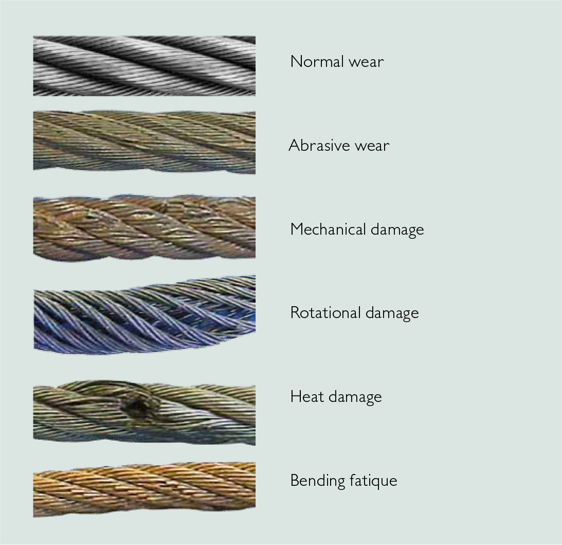
Due to the wide variety of service conditions for wire ropes, they are susceptible to many types of inadequacies and failures. It is important for consumers to frequently inspect wire ropes for signs of wear and fatigue. Wire ropes will inevitably fail if not used according to manufacturing limitations or when routine inspections for fatigue and wear are not properly performed. Eventually, all wire ropes are removed from service when they meet established discard criteria.
A failure analysis of a broken multi strand 71mm steel wire rope used in the main towing winch was carried out. The wire rope was failed during a bollard pull test. The wire rope was a new one and had failed during the first use. The wire rope was in IWRC/ RHO 6X41 constructions. Fig.1 shows the typical cross section of the wire rope. The failure investigation is performed by chemical and metallurgical examinations.
(ii) the uniformity and cleanliness of the microstructure of the rope steel and the effect of microstructure on crack initiation and propagation, and
1) Chemical analysis of steel wire rope is presented in Table 1. The analysis showed that it is made of high carbon steel corresponding to AISI 1074 grade, and galvanized with zinc to resist corrosion.
2) The microstructure observed under optical microscope and is shown in Figs. 2. It was typical of a drawn ferrite–pearlitic steel wire with heavily cold worked micro structure. Further examination of microstructure of the failed wires did not indicate any sign of metallurgical problems such as de- carburized layer, nonmetallic inclusions, or martensite formation. In addition, the wires were free from any sort of corrosion and pitting. Therefore, corrosion had no role in the failure of wires.
4) Table 3 represents the tensile values of the wire. The result indicates relatively less value comparing the metallographic results and the mill test certificate supplied by the Client. Figs. 3 showing Stress- Strain during tensile testing of the wire
The high hardness values, chemical composition, and the pearlitic structure of wires indicating that this is a type of extra extra improved plow steel (EEIPS) grade wire ropes. These types of wires have typically higher load-bearing capacity as compared with other grades. They are considered as heavy-duty wire ropes. The minimum tensile strength of EEIPS is 2160 N/mm2. (Ref. API Spec 9A)
5) The fractured ends of group of wires were visually inspected. Majority of wires failed in shear, and the remaining had cup-and-cone fracture, some of which are shown in Fig. 4.
Fractographs of broken wires in the form of cup and cone and shear are shown in Fig. 5 and Fig.6. Tensile overload fracture occurs when the axial load exceeds the breaking strength of the wires. This type of fracture usually appears in ductile manner, either in the form of cup and cone or in shear mode. In the former case, there is a reduction at the fracture which is called necking, whereas in the case of the latter, fracture surface is inclined at 45degree to the wire axis. In both cases, ductile dimple formations are clearly observed and confirm the tensile overloading of wires.
Every wire rope failure will be accompanied by a certain number of tensile over load breaks. The fact that tensile overload wire breaks can be found therefore necessarily mean that the rope failed because of an overload. The rope might have been weakened by fatigue breaks. The remaining wires were then no longer able to support the load, leading to tensile overload failures of these remaining wires.
Only if the metallic area of the tensile overload breaks and shear breaks combined is much higher than 50% of the wire rope’s metallic cross section is it likely that the rope failed because of an overload.
Shear breaks are caused by axial loads combined with perpendicular compression of the wire. Their break surface is inclined at about 45degree to the wire axis. The wire will fail in shear at a lower axial load than the pure tensile over load.
If a steel wire rope breaks as a consequence of jumping a layer or being wedged in, a majority of wires will exhibit the typical 45degree break surface.
In the instant case the wire rope was failed at 100 Ton or even less. As the breaking load of the wire rope is 353 Tons, there is no reason for a tensile over load breaks in an axial direction and that too considering the fact that the wire rope was failed during a bollard pull test. Fig. 7 shows the maximum stress generations in the wire rope at 100 Ton under normal bollard pull test. More over the metallurgical investigation is also not suggesting for any factors that fostering an axial overload failure.
The failure of the wire rope was studied in detail. In order to investigate the problem metallurgical and mechanical post failure analyses were performed. The wire rope was made of AISI 1074 grade steel, and it was a type of EEIPS. The microstructure was composed of severely deformed and elongated ferrite–pearlite, and no other phase formation or nonmetallic inclusions could be detected. The morphologies of fractured surfaces indicated that the wires were mainly failed in shear mode and few in tensile mode. Owing to galvanized coating, the wires were free from corrosion.
The tensile strength of the wire material is less than the required value. The required tensile strength of EEIPS is 2160 N/mm2 and the obtained value is 2059 N/mm2. But this factor is not a reason for the current failure of the wire rope. The said point is substantiated by the following:
It is concluded that the wire rope was failed due to shear breaks. Shear breaks were caused by high axial loads combined with perpendicular compression of the wire. It is worthwhile to note that the rope was failed in its first usage. The shear break is linked to the lapses during the installation/ spooling of the wire rope.
b) Lack of pretension of lower rope layers during spooling. In the absence of proper pretension the upper layers might be pulled in between the lower layers during loading.
c) Under high tension, the rope tends to be as round as possible. With no load, a rope can be deformed and flattened much easily. Highly tensioned upper layers will therefore severely damage loose (and therefore vulnerable) lower layers.

Wire ropes with diamond beads used in machines for cutting blocks of stone are subjected to fatigue, contact fatigue, corrosion and corrosion-fatigue loads in an aggressive environment.
As shown in Figure 1 1-3, multi-wire machines for cutting blocks of stone are made of two structural main components: the supporting structure, fixed with flanged bolts to the ground, (1 in Figure 1), and a vertical moving part 4 (Figure 1). Several wire ropes with diamond beads are put in motion by a driven drum (2 and 7 in Figure 1). The tensioning mechanical system (9 in Figure 1) allows to apply a tension to the wire ropes with diamond beads while the machine is cutting the stone blocks. Several pulleys guide the wire ropes; up to 80 wire ropes can be used and mounted in parallel on the structural component 4 and on several pulleys. the motorized drum is the component 3 in Figure 1 and a three-phase asynchronous electric motor is mounted on the machine and puts the drum and the wires in motion. Wire ropes with diamond beads are the cutting tools of the machine and the designer must take care of such components when mounted on the machine. It is well known that the structural behavior of steel wire ropes, composed of several strands, is complex and multiaxial stresses, along with contact fretting stresses, must be managed. Working conditions of the wire ropes have to be strictly controlled and checked periodically.
Notwithstanding there are many literature references on the study of the damage of wire ropes, few research references can be found in the literature, as far as the author knows, that would allow to understand their structural behavior in terms of damage or failure analyses 4-11. In 4 Authors report a study on the diamond wire cutting of concrete materials. Wire cutting with diamond technique was used in the United States until the early 1980s and allowed to cut reinforced concrete structures, regardless of thickness and reinforcement content. In 5 an innovative and optimized design of automatic adjustment system for beaded rope of new diamond wire sawing machine is reported, while in 6 the mechanics of sawing granite with diamond wire is considered. Research on cutting performance optimization of diamond wire saw is deepened in 7. In these papers the structural design of the wire rope with diamond beads is introduced and the mechanical structure and control of the adjusting device of the diamond wire saw are described. Working parameters are transmitted via wireless signals to achieve remote control. Mechanics of cutting procedure is deepened and mechanical simulation and optimization models of the wires with diamond beads are proposed. Many references are available on the study of wire ropes without diamond beads 8-11; such references allow to understand the mechanisms of failure in case of absence of the beads: unfortunately, the Author pf this paper found that the structural fatigue and corrosion-contact-fatigue behavior of the wire rope is highly influenced by the presence of the diamond beads.
This paper contains the results of the observation of surface damage of wires used in multi-wire machines for cutting blocks of stone and the optical analysis of beads for 2.35 mm cables. The cables are used as a support for pearls equipped with diamond inserts for cutting stones (beads) (Figure 2).
The samples were taken from wire ropes having 2,35 mm diameter. The wire rope is composed of 7 strands wires, one of which is located at the centre of the wire rope (“soul”). Each strand contains 7 single wires having 0.3 mm wires diameter (Figure 5).
The study was conducted by means of microscopic analysis, X-ray microtomography and tests with penetrating liquids. For the first, two Leica stereoscopic microscopes (MZ 75 with magnification up to 50x and microscope with magnification up to 40x) with digital camera (Canon Powershot S50 and Canon EOS 1100D) and an Opto-De monofocal optical microscope with magnifications were used up to 400x with Motic 2300 USB 2.0 acquisition camera. A new stereoscopic optical microscope mod. ZENITH SZM-4500 Trinocular Zoom 7x-45x with additional lens 2x mod, ST-087 2x for 14x-90x magnification and a variable double LED illuminator mod. ZENITH CL-31 with double jointed self-standing arm. The images were taken with a USB micro-camera Mod. OPTIKAM B-3 complete with optics. The effectiveness of the protective plastic coating was evaluated by pouring liquids (blue ink) on the cable.
Significant sections of the beaded wire as shown in Figure 4 were investigated. Section X.1 was not considered but we focused on the evaluation of the centering of the cable in the beads. The sections were obtained using a metallographic cutting machine.
The wire ropes with beads were also observed by unwinding the strands and the core both by opening the individual strands and by releasing the individual wires before proceeding with the observation. Figure 5 shows two examples of preparation of a stranded cable and single strands and wires.
Figure 6 shows two examples of the cracked surfaces of the wires. Those cracks greatly affect the fatigue resistance of the whole wire rope with beads.
To evaluate the effect of the environment on the wire rope, tests were carried out with penetrating liquids (blue ink). Liquids were poured onto the flexed sample to simulate operational behavior. Figure 8 shows the penetrating liquids experimental test.
Contact between the wire rope and the beads was observed (Figure 9). Beads and the wire rope are made of different materials and this might cause corrosion of the wires in the rope, along with contact fatigue damage.
The wire ropes studied in this work are designed with low fatigue resistance safety factors (2-3). Previous analyses helped in reaching some useful conclusions 3-10.
Detachment of brass or zinc coatings which, being thin, are unable to adhere to the wire at the cracks. Causes can also be found in the straightening operation and incorrect handling of the ropes.
Observations and analysis of the damaged wire ropes allowed to highlight that the beads have no continuous side surface and at the discontinuity the finish is very poor. Moreover the insertion of the diamond chips is not uniform. The insertion of the splinters causes localized lifting of the material. This could cause premature detachment of some of them. Wire ropes are mechanical components that work in a complex stress state with contact loads, wear, corrosion and fatigue resistance problems. The presence of the diamond beads is a further stress concentration, with corrosion and contact wear fatigue problems if the beads come into contact with the wire rope during assembly or in working condition.
The advice is to product wire ropes with beads in which the centering of the cable with respect to the bead is carefully controlled. No contact between rope and bead should occur. According to the results and observations this is the most important advice for producer of the ropes with diamond beads.
This paper reports the failure analysis of the damage mechanisms of wire ropes with diamond beads mounted in machines for cutting stones. Wire ropes with diamond bead are cutting tools subjected to fatigue, corrosion-contact-fatigue stresses. Cracks and defects are present in the strands of the wire ropes, generated during the production process: these cracks are further sources of stress concentrations. The observation at the microscope, and the penetrating liquids analyses, highlighted that the most important advice to give to the producer of the wire ropes with diamond beads is to product components in which the centering of the cable with respect to the bead is carefully controlled.
Pedrini, G., Baragetti, S., 2016, “Multi-wire machine for cutting blocks of stone and wire tensioning device”, International Patent n° WO 2016/071936A1.
Bangju Wei et al, 2020, “Innovative and optimized design of automatic adjustment system for beaded rope of new diamond wire sawing machine”IOP Conf. Ser.: Mater. Sci. Eng. 892 012078.
Janusz Stefan Konstanty, 2021,”The mechanics of sawing granite with diamond wire”, The International Journal of Advanced Manufacturing Technology (2021) 116:2591–2597.
Liu S., Sun Y.Send mail to Sun Y., Jiang X., Kang Y., 2022, “A new MFL imaging and quantitative nondestructive evaluation method in wire rope defect detection”, Mechanical Systems and Signal Processing, vol. 163.
Peng, Y., Wang, G., Zhu, Z., Jiang, F., Chen, G., 2021, “Effect of low temperature on tribological characteristics and wear mechanism of wire rope”, Tribology International, vol. 164.
Wang et Ali, 2021, “Tribological properties and residual strength of wire rope with different strands during the interlayer-transition stage”, vol. 480-481, Wear.
Bassir Y., et Ali, 2021, “Comparative study of the service life of a central core and a helical strand constituting the same rope”, vol. 247, Engineering Structures.
In 1998, a crane load line broke while lifting the south topside module of the Petronius platform, dropping the module into the Gulf of Mexico. The cost was estimated to be around 116 million US dollars. Since 1999 more than 60 people have been killed as a result of wire ropes breaking and more than 65 associated injuries.
Not many people appreciate that there are literally thousands of wire rope designs, most of which can be put into a specific category. According to BS ISO 4309 2010 there are currently more than 25 categories of crane wire rope, each with differing characteristics and also different discard criteria. Deterioration can be measured, counted or calculated and the wire rope eventually taken out of service based on sophisticated discard criteria published in chosen standards, codes of practice or users handbooks.
Unfortunately there is no simple answer to either of these questions. All wire ropes will eventually break due to corrosion, wear or fatigue even if they are maintained and used properly. Unpredictable wire rope failures will inevitably occur, quite often when you least expect it if the discard criteria is ignored, or those using the equipment are ignorant of it.
James Dawes of Topeka, Illinois, was killed in 2008 after being struck by the boom of a Link-Belt crane; the accident was caused by the boom hoist wire rope breaking. The crane rope had been inspected, but a report said that the inspector failed to reject the rope showing a high number of visible wire breaks. Premature or unexpected wire rope failures can also be attributed to poor manufacture, incorrect handling and storage, poor installation technique, poor selection or fitting of its termination, infrequent or inadequate inspection and poor maintenance. Of course there is always the possibility that mechanical damage can occur and this is usually attributed to human error.
It is necessary, particularly during offshore operations that frequent inspections are carried out over the whole length of the working part of all steel wire ropes. The frequency of inspections should be based on the severity of use and risk assessment and particular attention should be paid to the critical areas of the wire rope; areas that are frequently running over sheaves, compensating sheaves and the rope termination to name a few.
If a wire rope has not been subjected to an abnormal environmental condition such as excessive heat, chemical attack or any corrosive solution and it has not been the victim of any form of mechanical damage, then trained operatives and inspectors can reasonably predict the length of time the steel wire rope is likely to last. That prediction, of course, will be dependent on the knowledge and experience of those making it coupled with known facts about the rope, its current condition and the application it is running on. The Inspector should be aware of the previous rope’s history, capacities of loads and the reeving systems employed together with the frequency of use etc.
Various standards and codes of practice have been written by recognized bodies and institutes based on the experience of experts or representatives of corporate organizations who have a vested interest. These standards do offer guidance on when a wire rope should be removed from service based on wear, abrasion and fatigue amongst others things, but none of these standards have any legal status except when they are called up by contract. Indeed they can all be supported or overturned in a court of law by an expert.
The users handbook, or more importantly the safe use instructions do have legal status. In many parts of the world these days, suppliers of cranes or any machinery for that matter, issue safe use instructions with new equipment. Modern applications employ modern wire rope and, in some cases, sheaves and pulleys that are made with materials other than steel. Original equipment manufacturers of such applications may impose discard criteria for the wire rope that is stricter than those in chosen standards. By law the user must follow manufacturers’ instructions.
Wire ropes will deteriorate much more quickly if they go dry and are allowed to remain in that condition. Tests have proven that a dry rope will lose up to 60 % of its expected life if it is not re-lubricated. There are differing schools of thought as to how wire rope should be lubricated. Some believe that a thin lubricant should be applied using a paintbrush. It is thought that this method allows the lubricant to penetrate. Experience has proven however, that thin penetrative lubricants will easily drain away or fly off in hot climates.
Another school of thought, and the one I stand on, is that grease should be pressure lubricated into the rope. This method, if applied properly, will ensure that the grease penetrates the rope pushing out the old lubricant with it and any possible corrosive agents such as salt water and sand. Any lubricant that is used must be compatible with the type that was applied previously and it is a good idea to consider the environment as well.
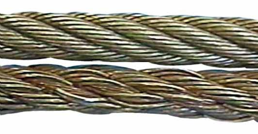
In any event, wire ropes usually announce that they are about to break. A series of individual wire breaks can be heard. These are likely to go on over several seconds and continuing for up to ten minutes before ultimate failure. Therefore, if operatives understand the warning signals, expensive incidents could be avoided.
Figure 2 shows two pieces of the same rope, the bottom portion quite clearly shows a progression of wire breaks. The operator was able to put the load down before disaster struck. The root cause of this fault was core deterioration brought about by internal corrosion.
To answer the other question on accountability, the list is extensive. Usually the first suspect is the wire rope manufacturer and that may be where the problem lies, but very often that is not the case. What if you were supplied the wrong rope for the application? Maybe you ordered the wrong rope or your buyer bought it from a cheap unapproved manufacturing source.
Perhaps your supplier is responsible, maybe he provided you with a rope that was produced to the wrong specifications. Would you know the difference? Perhaps you were sold a rope that had been stored in the suppliers or manufactures stock for a number of years and, whilst it was there, it hadn’t been properly maintained. Maybe the rope had been badly handled or installed incorrectly. The list of possibilities is endless.
In 1999 a ropeway in the French Alps snapped causing 21 deaths. In 2003, a ropeway wire rope snapped and 7 people died and a further 42 were injured. In 2007 a crane wire rope snapped at New Delhi’s metro, the entire structure tumbled down crushing workers underneath, six people were killed and 13 more were injured. In 2009 26 people were killed and 5 people were injured when a rope failed in a mine and a further 6 people were injured when a lift rope broke inside London’s Tower Bridge.
If you find yourself in the unfortunate situation after the unthinkable premature failure of a wire rope, then you might like to know that there are independent analytical services capable of determining probable cause. One of these is Doncaster Analytical Services Ltd (DAS), they have an independent metallurgical laboratory providing factual analysis and testing of wire rope for any reason (contact Mr Shui Lee, Technical Director, Tel +44(0)1302 556063, email: shui.lee@doncasteranalyticalservices. com).
You do not need a wire rope to fail in order to learn. Careful analysis of discarded ropes can also give you valuable information about your application, the way it operates, and the rope you have been using.
Based on this information, a trained, skilled and experienced inspector will be able to advise on a better crane or wire rope design, or to an improvement in maintenance procedures and safety.
But on one particular day in early May of 2009, it wasn’t a boom reaching toward the big Texas sky that was causing people to stop and stare; it was one that was lying in a heap just beside the water, lattice sections bent and lacings twisted into mess of mangled steel and frayed wire rope. “I got the call to investigate the cause of loss on a Manitowoc 888 that was being used to drive underwater pilings at a dock in Port Isabel,” says JR Bristow, of Bristow Truck and Equipment Specialists, an organization based in Ridgewood, NJ that provides failure analysis and appraisals, among other things, for heavy equipment. “The operator was hoisting the boom when it just sort of gave out and crashed to the ground. No one was hurt, but the boom was in bad shape. The initial reserve was set at $500,000.”
Though a half million dollars wasn’t a total loss – the crane was valued at $1.5 million – it was a pretty hefty price to pay for something that, as it turned out, could have been avoided. On lattice-type cranes, booms are raised and lowered using boom hoist wire rope, and when that wire rope shows surface wear or corrosion, or worse, has broken wires within the rope strand, it can fail. It’s usually just a matter of time.
The subsequent investigation that followed revealed that the wire rope used to hoist the boom of the Model 888 had been in an out-of-service condition for quite some time, due to lack of proper lubrication.
“An examination of the failed boom hoist wire rope revealed that the wire rope had gone without the proper lubrication, which was the responsibility of the insured per the attached lease agreement,” Bristow remembers. “I also noted significant broken wires within the rope strands at an average of six to 12 per strand lay. Clearly, if the insured had performed a daily inspection of the boom hoist wire rope as required, that incident would not have happened.”
The broken strand condition that Bristow observed was caused by load cycles that occurred during boom up and boom down functions that were part of the daily operation of the crane. Simultaneous compression and expansion of the wire rope usually occurs as it travels over the hoist sheaves, and that causes the gradual deterioration of the strand wires.
Like many other segments of the crane and rigging industry, the nuances of wire rope are complicated and varied. Considerable time, money and resources have been invested in new technology, new inspection suggestions and new manufacturers. And rightly so. As was the case in Bristow’s example earlier, there’s quite a bit at stake in terms of both human capital and equipment cost.
Python High Performance wire rope, a wire rope manufacturer that has produced a number of resources to assist people in understanding and ultimately purchasing wire rope, clarifies the structure of wire rope on its website www.pythonrope.com.
Python’s site explains that a typical wire rope can contain hundreds of individual wires. These wires are fabricated and formed to operate at close bearing tolerances to one another. When a wire rope bends, each of its many wires slides and adjusts in the bend to accommodate the difference in length between the inside and the outside bend. The sharper the bend, the greater the movement, and the greater capacity for stress on the wire rope.
While manufacturers of wire rope are many and varied, each of the wire ropes they produce have three basic components:The wires, which form the strands and collectively provide the rope strength
According to Python’s site, the greatest differences in wire ropes are found in the number of strands, the construction of strands, the size of the core and the lay direction of the strand versus the core. But what does that mean for the layperson? What should he or she look for when purchasing wire rope?
Tony Fastuca, vice president Python America & High Performance Products, says that most people buy rope based on four ideal standards. “Abrasion resistance, fatigue resistance, flexibility and strength. Those four typical standards often weigh into a purchase decision: he says. “A buyer sometimes has to give a little in one area to get a bit more in another, but a lot of buyers are looking for a good balance of those four standards.”
Whereas other products usually come with an expected lifespan, wire ropes don’t really have an average operational life. “There are records that exist of wire ropes getting two to three years of use, sometimes longer,” says Fastuca. ”But it’s about the level of wear on the rope, not the length of time it’s been in service.”
Just as the crane itself needs to undergo frequent and period inspections, the wire rope does, too. Fastuca talks of the so called “A,B,Cs” of wire rope abuse – abrasion, bending, crushing.
The principle goal of a wire rope inspection is to find potential problems before they manifest into incidents or serious accidents. Inspections should be performed slowly and methodically, with a keen eye for corrosion or broken wires or sections of rope that look questionable. Because the reality of wire rope is that it will fail if it becomes worn out, overloaded, damaged, misused or improperly maintained. It can lead to huge headaches for companies that try to take shortcuts or don’t properly maintain it – a risk that just isn’t worth taking.
![]()
Present work describes the failure analysis of AISI 304 stainless steel consisting of 7x19 construction lanyard wire rope which has failed during service. The microstructures and properties of failed wire rope have been investigated and compared with unused wire rope. Both the periphery and fracture surface of the wire rope display the presence of corrosion debris enriched with O and Cl. The fracture surfaces of the failed and unused wire ropes display intergranular and dimples, respectively…Expand

The 6 x 19 classification of wire ropes includes standard 6 strand, round strand ropes with 16 through 26 wires per strand. The 6 x 36 classification of wire ropes includes standard 6 strand, round strand ropes with 27 through 49 wires per strand. Although their operating characteristics vary, all have the same weight per foot and the same nominal strength, size for size.
While the 6 x 19 ropes give primary emphasis to abrasion resistance in varying degrees, the 6 x 36 ropes are important for their fatigue resistance. This fatigue resistance is made possible by the greater number of small wires per strand.
Although there are exceptions for special applications, the constructions in 6 x 36 classification are primarily designed to be the most efficient for each rope diameter. As the rope size increases, for instance, a large number of wires can be used to achieve required fatigue resistance, and still those wires will be large enough to offer adequate resistance to abrasion.
In this construction, each strand has nine outer wires over nine smaller inner wires over one large center wire. A comparison of cross-sections shows that these outside wires are larger than those of the 6 x 25FW or 6 x 26WS. Therefore, its resistance to abrasion is increased, but its fatigue resistance is decreased. This is a good rope to withstand abrasion or crushing on the drum.
To most wire rope users, 6 x 19 means 6 x 25 filler wire. It is the most common rope in the 6 x 19 classification. This rope has a good balance between both abrasion resistance and fatigue resistance in relation to other ropes.
This construction has better resistance to abrasion than a 6 x 25FW. It also features a compact construction with solid support for the wires; hence, it has a high resistance to crushing. Its number and relative size of the inner wires add to the stability of the strand and gives it a fatigue resistance comparable to a 6 x 25FW.
A standard 6 x 26WS construction provides the best rope for a wide range of applications. In general, we recommend the use of a 6 x 26WS in any application where a 6 x 25FW is used.
In most rope sizes, only one 6 x 36 classification rope is made. These constructions were selected to provide fatigue resistance without having wires that are too small.
The greater number of wires in the 6 x 36 classification makes these ropes more susceptible to crushing. This can be minimized, however, by specifying an Independent Wire Rope Core (IWRC) and by using well-designed sheaves, grooved drums and proper operating techniques.
Rotation-resistant ropes can frequently provide the best and most economical service in specific applications when you choose, handle and use them properly.
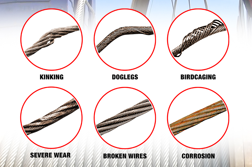
Contra-helically laid, rotation-resistant ropes are different from standard ropes because they"re designed to reduce rope torque. Modes of failure and wear for rotation-resistant ropes can differ from those for standard rope constructions. The very nature of these ropes requires special handling, selection and usage not encountered with standard constructions. They are susceptible to kinking, crushing and unbalancing in the form of "core pops" and "birdcages" Use extreme care to avoid operational practices that can possibly lead to these conditions.
Rotation-resistant ropes should not be used with swivels that allow rope rotation -- or in single part lifts where the load can rotate. Rotation will cause a reduction in strength, unequal loading in the rope and possible rope unbalance. If any significant change in diameter is found in a short length of a rotation-resistant rope, the rope needs to be replaced.
These ropes should be replaced when you see two randomly distributed crown wire breaks in six rope diameters -- or four randomly distributed crown wire breaks in 30 rope diameters.
Because rotation-resistant ropes are special, there are separate design, maintenance, inspection and removal criteria established for them by applicable industry regulations and standards.
In an application where a single-part hoist rope is used to lift a free load -- or where rotation-resistant properties are essential for rope performance -- the 19 x 7 can be used. Its rotation-resistant characteristic is achieved by laying six strands around a core strand in one direction, then laying 12 strands around the first operation in the opposite direction. Thus, when the rope is in tension, opposing rotational forces are created between the inner and outer layers.
In addition, frequent and regular inspection for broken wires is critical when using this rope. Due to its design, the 19 x 7 construction has a relatively low reserve strength. This can result in short service life between the point in time when the broken wire removal criteria are met and when actual rope failure occurs.
In a multi-part wire rope system where the blocks have a tendency to twist -- or for a single-part hoist line that doesn"t require the degree of rotation-resistant properties found in a 19 x 7 rope -- the 8 x 25 Resistwist rope has found successful application. The rotation-resistant characteristic is achieved by laying the eight outer strands around an independent wire rope core so these strands are in the opposite direction to the lay of the core. Thus, when the rope is in tension, opposing rotational forces are created between the core and the outer strands.
Though not as rotation-resistant, the 8 x 25 Rotation Resistant rope is more stable than a 19 x 7 rope. It also has increased resistance to bending fatigue and crushing. This is achieved through the use of eight-strand construction with an independent wire rope core.
Like any application where an installation"s rope type is changed, the 8 x 25 Rotation Resistant rope should be substituted only after carefully comparing specifications and strength requirements.

A wire rope is a type of cable that includes several wire strands laced together to form a single wire. Generally, both the terms “wire” and “rope” are used interchangeably with “wire rope”; however, according to the technical definition, to be labeled a wire rope, the cable must have a thickness of at least 9.52 mm. As a versatile, high load capacity alternative to natural fiber ropes such as hemp and manila, wire rope provides motion transmission through nearly all angles, tie down, counterbalance, guidance, control, or lift.
Modern wire rope was invented by Wilhelm Albert, a German mining engineer, between 1831 and 1834. He developed them in order for work in the mines in the Harz Mountains. This rope replaced weaker natural fiber ropes, like hemp rope and manila rope, and weaker metal ropes, like chain rope.
Albert’s rope was constructed of four three-stranded wires. In 1840, a Scot named Robert Stirling Newall improved upon this model. A year later in the United States, American manufacturer John A. Roebling started producing wire rope, aimed at his vision of suspension bridges. From there, other interested Americans, such as Erskine Hazard and Josiah White, used wire rope in railroad and coal mining applications. They also applied their wire rope techniques to provide lift ropes for something called the Ashley Planes project, which allowed for better transportation and increased tourism in the area.
Approximately twenty-five years later, back in Germany in 1874, the engineering firm Adolf Bleichert & Co. was founded. They used wire rope to build bicable aerial tramways for mining the Ruhr Valley. Years later they built tramways for both the Wehrmacht and the German Imperial Army. Their wire rope systems spread all across Europe, and then migrated to the USA, concentrating at Trenton Iron Works in New Jersey.
Over the years, engineers and manufacturers have created materials of all kinds to make wire rope stronger. Such materials include stainless steel, plow steel, bright wire, galvanized steel, wire rope steel, electric wire, and more. Today, wire rope is a staple in most heavy industrial processes. Wherever heavy duty lifting is required, wire rope is there to facilitate.
Wire rope is strong, durable, and versatile. Even the heaviest industrial loads may be lifted with a well-made wire rope because the weight is distributed evenly among constituent strands.
There are three basic elements of which wire ropes are composed: wire filaments, strands, and cores. Manufacturers make wire rope by taking the filaments, twisting or braiding them together into strands, and then helically winding them around a core. Because of this multiple strand configuration, wire rope is also often referred to as stranded wire.
The first component, the filaments, are cold drawn rods of metal materials of varying, but relatively small diameter. The second component, the strands, can individually consist of as few as two or as many as several dozen filaments. The last component, the core, is the central element around which strands are wrapped; wire rope cores maintain a considerable amount of flexibility, while increasing strength by at least 7.5% over the strength of fiber core wire ropes.
The helical winding of the strands around the core is known as the lay. Ropes may be right hand lay, twisting strands clockwise, or they may be left hand lay, twisting strands counter-clockwise. In an ordinary lay, the individual strands are twisted in the opposite direction of the lay of the entire rope of strands to increase tension and to prevent the rope from coming unwound. Though this is most common Lang"s lay has both the strands and the rope twisted in the same direction while alternate lays, as the name suggests alternate between ordinary and Lang style lays. While alternative rope designs are available, the helical core design is often favored, as it allows a wire cable to hold a lot of weight while remaining ductile.
There are many design aspects that wire rope manufacturers consider when they are creating custom wire rope assemblies. These include: strand gauge (varies based on application strength, flexibility, and wear resistance requirements), wire rope fittings (for connecting other cables), lay, splices, and special coatings. Specially treated steel cable and plastic coated cables, for instance, are common to many application specific variations of wire rope such as push pull cable assemblies used in transferring motion between two points.
Suppliers typically identify wire cable by listing both the number of strands and the amount of wires per strand respectively, though stranded cable may alternatively be measured by their lay and length or pitch. For example, a door-retaining lanyard wire rope is identified by its 7 x 7 construction, and wire rope used for guying purposes is identified by its 1 x 19 construction. The most common types are 6 x 19, 6 x 25, 19 x 7, 7 x 7, 7 x 19, 6 x 26, and 6 x 36.
An ungalvanized steel wire rope variety. This uncoated wire rope can also be designed to resist spinning or rotating while holding a load; this is known as rotation resistant bright wire rope.
Also called a coiled wire rope, a coiled cable is a rope made from bundles of small metal wires, which are then twisted into a coil. Wire rope and cable can come in a huge variety of forms, but coiled cables specifically provide the benefits of easy storage and tidiness. Unlike other wire ropes, coiled cables do not require a spool for storage. Because it has been coiled, the cable will automatically retract into its spring-like shape when it is not in use, making it incredibly easy to handle.
A type of high strength rope, made of several individual filaments. These filaments are twisted into strands and helically wrapped around a core. One of the most common types of wire rope cable is steel cable.
Wire rope made not as one solid piece, but as a piece made up of a series of metal links. Wire rope chain is flexible and strong, but it is more prone to mechanical failure than wire rope.
Push pull cables and controls are a particular type of control cable designed for the positive and precise transmission of mechanical motion within a given system. Unlike their counterpart pull-pull cables, these wire rope assemblies offer multidirectional control. Additionally, their flexibility allows for easy routing, making them popular in a number of industrial and commercial applications.
Iron and steel are the two most common materials used in producing wire ropes. A steel wire is normally made from non-alloy carbon steel that offers a very high strength and can support extreme stretchable forces. For even more strength and durability, manufacturers can make stainless steel wire rope or galvanized steel wire rope. The latter two are good for applications like rigging and hoisting.
Technically, spiral ropes are curved or round strands with an assemblage of wires. This gathering of wires has at least one cord situated in the opposite direction of the wire in the outer layer of the rope. The most important trait of this rope is that all the wires included are round. The biggest benefit of this category of rope is that it does not allow the entrance of pollutants, water, or moisture.
Contain an assemblage of strands placed spirally around a core. Stranded rope steel wire patterns have different layers that cross each other to form an even stronger cable or rope. Stranded ropes contain one of three types of core: a fiber core, a wire strand core, or a wire rope core.
Provide an added level of security to a manufacturing production application. Wire rope slings are made from improved plow steel wire ropes that, apart from offering added security, also provide superior return loop slings. Plow steel wire ropes improve the life of a mechanism by shielding the rope at its connection points. The key objective of wire rope slings is to enhance the safety of an application while increasing its capacity and performance. Rope slings are also available in various sling termination options, such as hook type, chokers, and thimbles.
The eye in this rope sling is made using the Flemish Splice method. Just like a typical sling, a Permaloc rope sling improves safety and provides reverse strength meaning that the uprightness of the eye does not depend on the sleeves of the metal or alloy. Additionally, permaloc rope slings offer an abrasion resistance feature that makes them long lasting.
These slings have all the features that most other slings offer. However, compared to their counterparts, Permaloc bridle slings provide better load control, wire rope resistant crushing, robust hooks and links that work for a longer duration, and help save on maintenance requirements.
Manufacturers produce wire rope for many different reasons; from cranes to playground swings, wire ropes have something for everyone. Among the many applications of wire rope are hoisting, hauling, tie down, cargo control, baling, rigging, anchoring, mooring, and towing. They can also serve as fencing, guardrails, and cable railing, among other products.
Some of the industries that make use of wire rope include industrial manufacturing, construction, marine, gas and oil, mining, healthcare, consumer goods, and transportation. Others include the fitness industry, which uses plastic coated cable products in weight machines, the theater industry, which uses black powder coated cables for stage rigging, the recreation industry, which uses plastic coated cables for outdoor playground equipment, and the electronics industry, which uses miniature wire rope for many types of electronic equipment and communications devices.
Wire ropes are typically made from cold drawn steel wire, stainless steel wire, or galvanized wire. They may also be made from a wide variety of less popular metals, including aluminum, nickel alloy, bronze, copper, and titanium. However, nearly all wire ropes, including control cables, are made from strands of cold drawn carbon steel wires. Stainless steel rope and cables are subbed in for highly corrosive environments. Galvanized cables and galvanized wire rope are popular for their increased strength and durability; these qualities are important to specialized ropes like galvanized aircraft cable.
A core may be composed of metal, fiber or impregnated fiber materials depending on the intended application. Cores may also be another strand of wire called an independent wire rope core (IWRC).
Wire rope, depending on its application, is subject to many standard requirements. Among the most common of these are the standards detailed by OSHA, ASTM International, and ISO. Per your application and industry, you’ll likely have others you need to consider. To get a full list, talk to your service provider.
To determine the safety factor, which is a margin of security against risks, the first step involves knowing the type of load that the rope will be subjected to. The load must consider the shock loads and blowing wind effects. The safety factor is characterized in ratios; typical are 4:1 and 5:1. If a ratio is 5:1, then the tensile strength of a wire rope must be five times of the load it will be subjected to. In some applications, the ratios can go up to 10:1.
By weighing all these factors carefully, the wire rope that you will buy will be safe to use and last considerably. For the best advice and guidance, though, don’t go it alone! Find a great wire rope supplier that you can trust. You’ll know you’ve found the right supplier for you when you talk to one that can not only fulfill your requirements, but shows that they are excited to go the extra mile for you. For a company like this, browse the list near the top of the page.
As the cables play an integral role in the safety of many operations and structures, careful analysis of a wire rope and all of its capabilities and features is vital. Important qualities and physical specifications you must consider include wire rope diameter, breaking strength, resistance to corrosion, difficulty of flattening or crushing, bendability, and average lifespan.
Each of the aforementioned considerations should be compatible with the specific application for which the rope is intended as well as the environment in which such operations are undertaken. Temperature and corrosive environments often require specially coated wire ropes with increased durability.
When you use your industrial wire rope, the first thing to remember is to not exceed your rope’s rated load and breaking strength. If you do not stay within these parameters, you risk causing your rope to weaken or even break.
Rust, kinks, fraying and even carefully performed splicing will all have an impact on the performance of wire ropes. To maintain the integrity of your wire rope assembly, you need to inspect them regularly and clean and lubricate them as needed. In addition, you need to store them out of the wet and cold as much as possible. Also wrap them up properly, so they are not kinked.
A high-carbon steel having a tensile strength of approximately 260,000 psi that is roughly fifteen percent stronger than Plow Steel. Most commercial wires are made from IPS.
A low carbon steel wire of approximately 10,000 psi, which is pliable and capable of repeated stresses from bending around small sheaves. This grade is effective for tillers, guys and sash ropes.
The manner in which the wires are helically wound to form rope. Lay refers specifically to the direction of the helical path of the strands in a wire rope; for example, if the helix of the strands are like the threads of a right-hand screw, the lay is known as a right lay, or right-hand, but if the strands go to the left, it is a left lay, or left-hand.
A classification of wire rope according to its breaking strength. The rank of grades according to increasing breaking strengths is as follows: Iron, Traction, Mild Plow Steel, Plow Steel, Improved Steel, Extra Improved Steel.
The act of fastening a termination to a wire rope through physical deformation of the termination about the rope via a hydraulic press or hammering. The strength is one hundred percent of the wire rope rating.
A grade of rope material that has a tensile strength range of 180,000 to 190,000 psi. Traction steel has great resistance to bending fatigue with a minimum of abrasive force on sheaves and drums, which contributes to its long use in elevators, from which the steel gets its name.
It is composed of wire strands that are braided together. Wire braid is similar to stranded wire. The difference between the two is the fact that stranded wire features strands that are bundled together, rather than braided.
Essential parts of cable assemblies, wire rope assemblies and wire rope slings that assist spliced or swaged rope ends in connecting to other cables and keeping cables and rope from unraveling.
A wire rope cable assembly is a metallic rope consisting of bundles of twisted, spiraled, or bonded wires. While the terms wire rope and cable are often used interchangeably, cables are typically designated as smaller diameter wire ropes, specifically wire ropes with a diameter less than 3/8 inch. Therefore, wire rope cable assemblies are typically utilized for lighter duty applications.
Or cable assemblies, are cables which are composed of many spiraled bundles of wire. These cables are used to support hanging objects, connect objects, pull or lift objects, secure items, and much more.
Wire rope wholesalers can sell an extensive range of wire rope and wire rope accessories at a very affordable rate as well as in bulk. Many of the additional wire rope equipment that wire rope wholesalers provide include: swivel eye pulleys, eye nuts, eye bolts, slip hooks, spring hooks, heavy duty clips, clevis hooks, turnbuckle hooks, anchor shackle pins, s hooks, rigging blocks, and much more. Wire rope fittings will generally improve the versatility of the wire and also prevent fraying.


 8613371530291