
wire rope failure causes free sample

Hoisting loads with a wire rope is a simple operation. Hook it up; lift it. Turns out, it’s more complicated than it appears. The details of setting up, inspecting, and maintaining lifts with wire ropes are not complicated, but are critical. A lift that goes awry is dangerous. A bad lift puts workers at risk. In this article, we discuss the causes of wire rope failure and how to avoid them.
Abrasion breaks are caused by external factors such as coming into contact with improperly grooved sheaves and drums. Or just hitting against some object during operation. Worn, broken wire ends is the result of an abrasion break. Common causes of abrasion breaks include:
Core slippage or protrusion is caused by shock load or improper installation of the wire rope. Excessive torque can cause core slippage that forces the outer strands to shorten. The core will then protrude from the rope. Wire ropes designed to be rotation-resistant should be handled carefully so as not to disturb its lay length.
Corrosion breaks cause pitting on the individual wires that comprise the rope. This type of damage is caused by poor lubrication. However, corrosion breaks are also caused by the wire rope coming into contact with corrosive chemicals, such as acid.
There are many ways the strands of a rope can be crushed or flattened. Improper installation is a common cause. To avoid crushing, you’ll want the first layer of the wire rope to be very tight. You’ll also need to properly break-in a new wire rope. Other causes of crushing include cross winding, using a rope of the wrong diameter, or one that it too long.
Cracks to individual wires are caused by fatigue breaks. Fatigue breaks happen because the wire rope is being bent over the sheave over and over again. In time, the constant rubbing of the wire rope against the sheave or drum causes these breaks. Sheaves that are too small will accelerate fatigue breaks because they require more bending. Worn bearings and misaligned sheaves can also cause fatigue. A certain number of broken wires is acceptable. The worker responsible for equipment inspection prior to use should know the American Society of Mechanical Engineers (ASME) standard for wire ropes. The ASME standard determines whether the wire rope must be replaced. (https://www.asme.org/)
Selecting the right wire rope for the job is critical. There is never a perfect rope. For example, you will need to make a tradeoff between fatigue resistance and abrasion resistance. There are several aspects to wire rope design to consider, including:
In general, the proper wire rope will have a strength rating high enough to handle the load. (Strength is rated in tons.) It can handle the stress of repeated bending as it passes over sheaves or around drums. How you attach the rope in preparation for the lift matters and should only be handled by properly trained workers.
The wire rope (and all the equipment involved in a lift) should be fully inspected prior to the lift. The worker performing the inspection should be well-versed in the types of damage that can cause a wire rope to fail. Using a checklist is highly recommended. This will ensure that the inspection is complete. Worker and supervisor signoff will increase accountability. Of course, the wire rope must be maintained according to the manufacturer’s instructions.
How a wire rope is stored, the weather conditions in which it is used, and how they are cleaned all affect its useful life. The Occupational Safety and Health Administration (OSHA) provides these recommendations: (Source: https://www.osha.gov/dsg/guidance/slings/wire.html)
Preventing wire rope failures starts with selecting the right one for the job. When in doubt, talk with your local equipment dealer. Be prepared to discuss your specific job requirements. A thorough inspection of the wire rope prior to using it is critical. Finally, properly store your wire rope. The selection, inspection, and care of wire rope is key to job safety.
Unfortunately, many phone calls into ITI Field Services begins this way, “We have had an incident with a wire rope and we believe the rope failed. How do we determine the cause of failure?”
Fortunately, the calls come in because wire rope users want to determine cause of failure in an effort to improve their crane, rigging and lifting activities.
A wire rope distributor received a hoist rope and sockets from a rubber-tired gantry. The rope and sockets were returned by the customer who believed the rope and sockets failed. The distributor hired ITI Field Services to conduct an analysis on the rope and sockets to determine the cause of the failure and to produce written documentation.
Based on the findings of the examination, fatigue-type breaks in the wires indicated that the wire rope lost significant strength due to vibration. There was no indication that the rope was overloaded. The poured sockets showed no evidence of abnormalities in the pouring method, wire zinc bonding length or the materials used in the speltering process. The conclusion of the inspection is that rope failed due to fatigue.
Wire rope examination is just one of the many services that is offered by ITI Field Services. ITI has some of the most highly-regarded subject-matter experts in the crane and rigging industry with experience in performance evaluations, litigation, accident investigations, manual development and critical lift planning reviews.

The best time to troubleshoot wire rope problems is while it is operating on the equipment. Unfortunately, due to the importance of keeping equipment running, the wire rope may be taken out of service before a wire rope engineer has the opportunity to examine it. The sample is then sent back to the wire rope manufacturer for cause determination. This article outlines the approach that one manufacturer of wire rope takes with these returned samples as well as troubleshooting on site. The lessons learned from these examinations should help prevent recurring problems as well as provide the answer to some puzzling wire rope reactions.
Much like a medical examiner or coroner, the director of engineering is called upon to perform an autopsy on a wire rope returned from the field. When a sample is sent in, the sender usually believes that there was some kind of “birth defect”. Oddly enough, it is the director of engineering that issued the birth certificate (test certificate) and is now responsible for determining the cause of death.
The most important thing to receive with the rope sample is proper documentation. Rope samples are often received with no paperwork, which delays the examination. Along with the rope sample, the following information should be supplied:
• changes – this would include changes in type of work; change in rope manufacturer or construction; equipment modifications, operator, lubrication etc.
As a rule, examinations are not performed on ropes from other manufacturers. Yet many ropes are received that were made elsewhere. Generally, this is not because of misrepresentation during the supply phase, but because of poor record keeping. It is recommended to use a wire rope inspection log where the user can enter the appropriate wire rope information along with the installation date. The wire rope manufacturer’s test certificate should also be stored with the inspection log. The inspection information that is recorded on the log is extremely valuable as the user can also monitor the rate of deterioration.
In one incident a user had experienced a total boom hoist rope failure. Samples of the rope were sent back and it was quickly determined that it was made by another manufacturer. The user was surprised because it had not bought a rope from that manufacturer for over three years. The company policy was to change boom hoist ropes at least every two years. Failure occurred because the rope was way beyond normal retirement criteria. This could have been picked up from an inspection form and the accident thus prevented. Of course, proper inspection techniques would have also prevented the failure.
The first part of the examination is to verify the rope construction. The manufacturer is not verified until the rope is disassembled so the marker can be obtained. The diameter is taken and compared to the diameter recorded at manufacture. The rope’s lay length is also measured and compared to the original measurement. The rope’s exterior surface is examined for wear and corrosion. If broken wires are present, they are counted and the type and location of fracture is noted and recorded.
Sometimes there may be deformation in the rope structure. This could be localised kinks, severe wire displacement or possibly a corkscrew or wave. If the latter condition is noted, the amplitude of the deformation and length of affected area is recorded. The rope is also examined for thermal damage. The rope is then disassembled and the internal rope is inspected much like the rope’s exterior, except that the degree of wire indentations (notching) is also examined.
All the findings are like clues that when put together with the background information determine the cause of failure. Many of the samples received have completely failed and should have been removed from service long before the time of failure. It is evident that they were not inspected thoroughly or in a timely manner. Other failures happened suddenly, like a jumped sheave or from a shock load. These are not inspection problems but either machine or operator related. These latter examples usually arrive in a condition that makes it obvious what has happened.
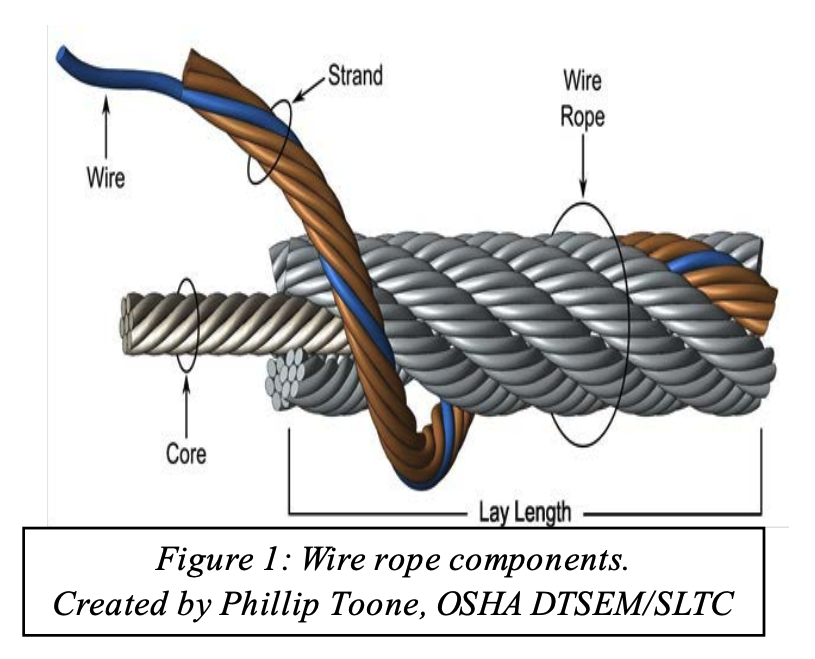
An example of this is shown in Figure 1 which shows a rope that has operated around an extremely small radius, perhaps from jumping a sheave. Operating around such a small radius has caused this coil like condition.
Figure 2 is an example of a rotation resistant rope from a pedestal crane that has experienced a shock load, resulting in the inner rope popping out suddenly.
Sometimes, a wire rope failure has to be investigated at the scene. Figure 3 shows a wire rope that has completely failed. On closer examination, the majority of the wire ends were cut in shear with some broken in tension. The fact that most of the wire fractures were in shear indicates that a sharp object had severed the rope.
Upon closer investigation, the sheave shown in Figure 4 appears to be the murder weapon. The rope evidently looped out of the sheaves somehow and when put back under tension straddled the sheave and was cut by the sharp edge.
If the rope is still operating on the equipment there is an opportunity to see the rope problem and how it relates to its environment. When troubleshooting in-situ, no assumptions are made. Essentially, some basic steps are followed that should provide all the information needed to make a cause determination.
• check the condition of the rope related equipment: drum – general condition drum grooves – radius and pitch kicker plates or wear plates – condition and position sheave grooving – correct shape and size sheaves – free to rotate and in good condition rope guards – correctly fitted and in good condition wear plates or rollers – condition
A simple trick is to paint the damaged area and see where the affected area is positioned during the operating cycle. Figure 5 is an example of a rope that was at the flange in the layer change transition point. The rope should have been retired before it made it to this condition. A simple drum end rope cut earlier in the rope life would have moved the rope before it became a problem. Slip and cut programmes extend rope life and should be considered for all drum applications (especially smooth face drums). Information gathered should determine the cause of the problem. The most common problems are:
Before contacting the manufacturer, review publications like the Wire Rope Users Manual published by the USA’s Wire Rope Technical Board. Samples of various problems are illustrated which can help the user make an immediate determination. If the cause cannot be identified, take down all the information as covered earlier and ask the original manufacturer for assistance. No matter what has happened to the wire rope, it leaves behind undeniable clues that when matched with site information provides the investigator with the answer to the problem. Wire rope always tells the story.
Maintain a record for each rope that includes the date of inspection, type of inspection, the name of the person who performed the inspection, and inspection results.
Use the "rag-and-visual" method to check for external damage. Grab the rope lightly and with a rag or cotton cloth, move the rag slowly along the wire. Broken wires will often "porcupine" (stick out) and these broken wires will snag on the rag. If the cloth catches, stop and visually assess the rope. It is also important to visually inspect the wire (without a rag). Some wire breaks will not porcupine.
Measure the rope diameter. Compare the rope diameter measurements with the original diameter. If the measurements are different, this change indicates external and/or internal rope damage.
Visually check for abrasions, corrosion, pitting, and lubrication inside the rope. Insert a marlin spike beneath two strands and rotate to lift strands and open rope.
Assess the condition of the rope at the section showing the most wear. Discard a wire rope if you find any of the following conditions:In running ropes (wound on drums or passed over sheaves), 6 or more broken wires in one rope lay length; 3 or more broken wires in one strand in one rope lay. (One rope lay is the distance necessary to complete one turn of the strand around the diameter of the rope.)
Corrosion from lack of lubrication and exposure to heat or moisture (e.g., wire rope shows signs of pitting). A fibre core rope will dry out and break at temperatures above 120°C (250°F).
Kinks from the improper installation of new rope, the sudden release of a load or knots made to shorten a rope. A kink cannot be removed without creating a weak section. Discarding kinked rope is best.

Copyright © 2013 Sheila Devasahayam et al. This is an open access article distributed under the Creative Commons Attribution License, which permits unrestricted use, distribution, and reproduction in any medium, provided the original work is properly cited.
A range of blends of polypropylene-polyethylene are investigated for their mechanical performances. These speciality polymer blends are chemically designed to suit high modulus/high load bearing mining wire rope applications subjected to continued bending and tensile stresses and fluctuating loads and are exposed to extreme weather conditions. In this paper we study the influence of different parameters on the performance of the wire ropes: chemistry of polymer, crystallinity of the polymer matrix, and the morphology. The FTIR and SEM studies revealed that the high fraction of polypropylene in polypropylene-polyethylene matrix lead to early failure as a result of incompatibility and phase segregation and high spherulite sizes of the polymer matrix.
Mining wire ropes are used for high modulus/high load bearing applications and are exposed to extreme weather conditions. The mining wire ropes are subjected to continued bending and tensile stresses and fluctuating loads, e.g., in drag rope, and shovel hoist rope applications. Historically wire ropes were made of only steel chains with a record of mechanical failure. The flaws in chain links or solid steel bars lead to catastrophic failure. Friction between the individual wires and strands, as a consequence of their twist, cause strand wear and heat resulting in accelerated rust and potential premature rope failure. Mining wire rope consists of several strands of steel wire laid (or “twisted”) into a helix featuring a 6 or 8 steel strand construction. The steel is normally made of non-alloy carbon steel with carbon content between 0.4% and 0.95%. The size and number of wires in each strand, as well as the size and number of strands in the rope greatly affect the characteristics of the rope. In general, a large number of small size wires and strands produce a flexible rope with good resistance to bending fatigue. The rope construction is important for tensile loading (static, live or shock), abrasive wear, crushing, corrosion and rotation. Plastic infusion helps achieve reduced rope fatigue from bending stresses by reducing the internal contact stresses between the strands and the core and provides improved fatigue and abrasion resistance and increased corrosion protection. A plastic-infused core provides a cushion for the outer strand and virtually eliminates interlayer contact wear. The plastic-infused core adds to the core support for the outer strands, further reducing internal stresses and promoting longer service life and under extreme conditions. Plastic-Infusion involves injecting specially engineered polymers under high temperature and pressure into the wire rope. Both the polymer and the wire rope are heated when the polymer is infused as the wire rope is drawn through specially designed dies. Passing the rope through a series of cooling troughs then solidifies the plastic. This plastic will not melt or soften from the heat of normal operating temperatures when in service and is also virtually unaffected by sunlight or cold weather during their life time (6 to 12 weeks). A set of plasticised ropes is expected to typically last between 6 - 12 weeks. Benchmark for these wire rope is identified visually as-all plastic still intact at the end of the ropes life, which only wears away due to mechanical abrasion to expose the crown of the strand (the highest point of the strand on a rope which has the thinnest plastic cover) on certain sections of the rope instead of peeling off entirely. Plastic delamination causes a hassle as it trips the machine off when the plastic pieces activate the slack rope indicator in the machine. A typical rope section is shown in
Other plastics of interest in wire ropes include, HMPE (High Modulus Polyethylene), Nylon®, Perlon® (Polyamide), Dacron®, Terylene® (Polyester), Polyolefins: Polypropylene and Polyethylene; Kevlar®, Twaron®, and Technora® (Aramid): Vectran® (LCAP—(Liquid Crystal Aromatic Polyester)): Zylon® (PBO-Poly-pphenylenebenzobisoxazole), Poly Vinyl Chloride, Low Density Poly Ethylene, High Density Poly Ethylene, P, nylon 6 (PA6), nylon 11 (PA11), polyvinylidenedifluoride and more [1]. Properties of these wire rope materials based on manufacturer’s specifications have been summarised by Barry Cordage [2].
Homopolymer of polypropylene (PP) are homogeneous with single phase, exhibiting large spherulite dimension which affect their mechanical properties adversely. However, the polymer blends/copolymers e.g., polypropylene-polyethylene (PP-PE) are immiscible in each other, and show decline in their mechanical properties due to their incompatibility. They show remarkable phase separation during crystallization. Phase segregation hastens yielding and fracture at interphase boundaries. The micro structure of the polymer matrix greatly influences the mechanical behaviour of the polymer products. Higher crystallinity leads to brittle fracture in polymers as opposed to the amorphous nature of the polymer. The factors affecting the crystallinity include the polymer processing, e.g., during polymer extrusion the slow cooling or the rapid cooling greatly affects the crystallinity in polymers [3]. In this study we focus on if the crystallinity behaviour of the polypropylene-polyethylene blend affects the performance of the mining wire ropes.
The Moly-Cop Ropes supplied the mining wire rope samples and the information on their mechanical performance as listed below: wire rope A > wire rope B > wire rope C - wire rope D > wire rope E. The manufacturers of these wire ropes have not released chemical compositions, structures of these wire ropes.
The chemical composition and the crystallinity of the plastic component of the mining wire ropes were studied using Perkin Elmer Spotlight 400 FTIR Microscope, a Fourier Transform Infrared (FTIR) spectrometer fitted with Harrick Grazing Angle ATR accessories. This technique probes the surface of a sample (up to 2 microns deep) with infrared energy of varying wavelengths. The detection limit of IR has been noted to be between 2% and 3% by weight of the total analysed sample. The technique allows transmittance or absorbance to be measured. The spectra were accumulated for 4 scans at a resolution of 4 cm−1 over the spectral range 500 - 4000 cm−1 at ambient temperature.
three isotactic bands at 1165 cm−1, 997 cm−1 and 977 cm−1 confirmed the presence of the isotactic polypropylene component in all the wire ropes studies. The presence of following CH2 bands at 2917 cm−1, 2860 cm−1, 1464 cm−1 and 718 cm−1, and the CH3 band at 731 cm−1, and 1379 cm−1 confirmed the presence of polyethylene component of these wire ropes. A reference spectra of PE-PP from FTIR library is included in the figures to corroborate the presence of PP-PE in the wire samples.
The crystallinity, Xc, for isotactic polypropylene of the wire ropes showed following trend: B < E < C < A < D. The evolution of crystallinity and the associated mechanical properties during polymer processing in the extruded polymer samples are attributed to different cooling rates. The crystallinity increases when the polymer sample is slow cooled [3]. It is believed that in slow cooling, the polymer chains are exposed near the maximum crystallization temperature for a longer period, and therefore, the crystallization is activated. In fast cooling, the polymer melt go through the maximum crystallization temperature very quickly, leaving most of the molecular chains in amorphous form. What this means is higher crystallinity results in a harder and more thermally stable, but also more brittle material, whereas the amorphous regions provide certain elasticity and impact resistance. Samples cooled slowly from the melt state, form larger and denser microstructures. Based on the mechanical performance trend of the samples, where sample A performed better than sample B showing following trend, A > B > C - D > E, the trend observed in the crystallinity, Xc of the samples could not be correlated with the performance trend.
Though the samples were identified to be copolymer of PP and PE, the ratio of the PP and PE in the wire rope samples have not been released. In order to investigate if the PP:PE could have bearing on the mechanical performance of the wire ropes, the proportion of polypropylene (PP) in the copolymer (Figures 9 and 10) was determined using the ATR-FTIR technique. The relative ratio of the absorbance (integrated area) of two peaks in the rocking wagging region, a peak at 1168 cm−1 characteristic for methyl group wagging in PP and a peak at 720 cm−1 arising from ethylene rocking and typical for HDPE were chosen [6,7].
est PP content compared to the other samples, followed by sample B and A leading to the proposition that the amount of PP could perhaps affect the performance of these wire ropes, that is high PP content as found in sample E could lead to the early failure in these samples.
The results indicate that perhaps the PP content of the matrix could be responsible for the observed differences in the behaviour in different mining wire ropes. In the present study it is observed from the SEM images (Figures 12-14) that as the % PP increased, the spherulite size increased, the crystallinity (
High modulus applications of homopolymer of polypropylene exhibiting homogeneous single phase, is limited by their large spherulite dimension affecting their mechanical properties adversely. This has led to a great deal of commercial interest In recent years in blends based on isotactic polypropylene and other polyolefins in nature due to improved mechanical strength, tensile strength, enivironmental stress cracking, low temperature impact properties exhibited by these blends.
chanical properties, including impact strength, strain at break and ductile to brittle transition, especially related to morphology are attributed to the strong phase separation leading to a coarse phase structure and low interfacial adhesion between the two phases. Previous studies on mechanical properties of the PE-PP blends reveal direct
correlation between the morphology and the tensile properties, the spherulite size and the crystallinity being controlled by the PE-PP ratio. The impact strength and adhesion are improved when the particles are smaller with narrower particles size distributions, and when there is stronger adhesion between particle and the matrix [10- 17]. Lovinger and Williams [18] correlated the morphological effects, such as spherulite sizes, inter crystalline links between lamellae, and the detailed structure of the two incompatible phases and of their mutual boundaries, with the tensile behaviour of PE/PP blends. They reported deterioration of mechanical properties as a result of incompatibility and phase segregation which hastens yielding and fracture at interphase boundaries. Studies have shown that yield stress and ultimate strength are improved with decreasing spherulite size, primarily because yielding and failure are commonly initiated at inter spherulitic boundaries. The PE in the blends reduce the average spherulite size, increase the overall crystallinity, promoting formation of intercrystalline links, and increases modulus and strength [13,19-21].
In present study the higher PP content in the sample E, with lower crystallinity but larger spherulite size is determined to be contributing to the observed early failure, as well as the higher void fraction compared to samples with lower polypropylene content (e.g., samples A and B).
The study pertaining to failure in mining wire ropes revealed all the samples were made of copolymer of polyethylene and Polypropylene, with different PP:PE content. Sample E exhibited higher polypropylene content, lower crystallinity and bigger spehrulite size compared to the other samples. The SEM results showed highly ruptured and segregated morphology for sample E. SEM images of samples A and B with lower % PP are ordered/ homogenised and well plasticised with uniformly distributed microcellular structures. Even though the crystallinity (crystalline content) results from FTIR study of all the samples appear to be comparable and not correlated to their performance characteristics, the spherulite size of samples could be directly correlated to their performance behaviour. The % PP had direct influence on the spherulite size with higher % PP showing larger spherulite structure and lower crystallinity while the higher PE content increased the crystallinity of the samples. It is concluded the larger spherulite size of sample E compared to the samples A and B, which showed smaller spherulite structures and relatively homogenised morphology samples contributes to the early failure in the sample E, as the higher PP content increases the viscosity and void fraction in samples. Performance characteristics of samples A and B are superior to sample E attributable to higher PE content resulting in smaller spherulite size. It is also concluded that sample with 50:50 PP: PE performed the best (sample A), where the microcellular structure uniformly distributed.
D. C. Yang, B. L. Zhang, Y. K. Yang, Z. Fang, G. Sun and Z. L. Feng, “Morphology and Properties of Blends of Polypropylene with Ethylene-Propylene Rubber,” Polymer Engineering and Science, Vol. 24, No. 8, 1984, pp. 612-617. doi:10.1002/pen.760240814
A. J. Lovinger and M. L. Williams, “Tensile Properties and Morphology of Blends of Polyethylene and Polypropylene,” Journal of Applied Polymer Science, Vol. 25, No. 8, 1980, pp. 1703-1713. doi:10.1002/app.1980.070250817
P. J. Phillips and J. Patel, “The Influence of Morphology on the Tensile Properties of Polyethylenes,” Polymer Engineering and Science, Vol. 18, No. 12, 1978, pp. 943- 950. doi:10.1002/pen.760181207
J. S. Petronyuk, O. V. Priadilova, V. M. Levin, O. A. Ledneva and A. A. Popov, “Structure and Elastic Properties of Immiscible LDPE-PP Blends: Dependence on Composition,” Proceedings of Materials Research Society on Nanomaterials for Structural Applications, Vol. 740, Boston, 2-6 December 2002, pp. 261-266.

Tyre bead grade wire is used for tyre making application. The wire is used as reinforcement inside the polymer of tyre. The wire is available in different size/section such as 1.6–0.80 mm thin Cu coated wire. During tyre making operation at tyre manufacturer company, wire failed frequently. In this present study, different broken/defective wire samples were collected from wire mill for detailed investigation of the defect. The natures of the defects were localized and similar in nature. The fracture surface was of finger nail type. Crow feet like defects including button like surface abnormalities were also observed on the broken wire samples. The defect was studied at different directions under microscope. Different advanced metallographic techniques have been used for detail investigation. The analysis revealed that, white layer of surface martensite was formed and it caused the final breakage of wire. In this present study we have also discussed about the possible reason for the formation of such kind of surface martensite (hard-phase).
Tyre bead grade with Cu-coating was conventionally used for tyre making application [1]. During tyre making operation at tyre manufacturer company, wire failed frequently during bending operation at brittle manner. During bending operation such kind of breaking was also happened at wire mill. Different breakages as well as defective samples have been collected from different coils. The wire manufactured by drawing process from 5.5 mm wire rod [2], [3]. Two stage of drawing process is involved to making of final wire. After the drawing operation stress reliving and Cu–Sn coating of wire was carried. The process details are mentioned in Fig. 1.
Two pieces of breakage wire samples were collected from the drawing mill for investigations. The samples were cleaned with acetone to remove dirt for visual examination prior to metallographic sample preparation. Visual examination is carried out in stereoscope. Surface appearance of the defects in all wire samples was of similar in nature. The fracture surface revealed finger nail type (Figs. 4 and 5). Crow feet like defects including button like surface abnormalities were observed on the broken wire samples. The defect was observed near the fracture end and which was very much localized in nature (Figs. 2 and 3).
Chemical analysis of wire samples was carried out using combustion infrared technique (LECO, TC600) for carbon and sulphur contents. An inductively coupled plasma atomic emission spectroscopy (ICP-AES) instrument was used to determine amounts of rest of the elements. The chemistry of wire sample confirmed to high carbon steel grade (C-70). Chemical analysis result is presented in Table 1.
Micro specimens were prepared from the fractured end as well as defect location of wire samples for conducting light optical microscopic examination and scanning electron microscopy (SEM). These samples were individually mounted in conductive mounting and polished by conventional metallographic techniques for scratch free surface. The polished samples were etched in 3% nital solution (3 mL HNO3 in 97 mL ethyl alcohol), and both un-etched and etched samples were examined in a light microscope to observe microstructural constituents. Un-etched sample shows surface defect in longitudinal as well in transverses direction (Figs. 6 and 7, Figs. 8–11). Etched microstructure of the longitudinal samples revealed presence of brown layer near the defect location. The thickness of the brown layer is around 30–40 μm (Fig. 7). From microstructure analysis the brown layer appeared to be of martensite (which was further verified by micro hardness value and SEM analysis; Table 2). Severe grain flow was observed along the defect location. The microstructure of the matrix revealed cold drawn pearlite structure (Figs. 9–11).
The micro hardness of different phases observed in the broken wire samples was determined in a pneumatically controlled automatic micro hardness tester (Leco-LM247AT). An applied load of 50 gf was used during testing, and several indentations were made to determine the hardness of different phases (Fig. 12). The average hardness of the matrix is about 461 HV, and the average hardness value of the brown phase is about 624 HV (Table 2).
Premature wire failures were observed during bending operation before tyre making process. The nature of the defects was of similar type in all the failed samples. The fracture surface was of finger nail type. Crow feet like defects including button like surface abnormalities were observed on the broken wire samples. The surface defect was observed near the fracture end and in localized manner. Etched microstructure of the longitudinal samples revealed presence of brown layer near the defect location. The thickness of the brown layer is around 30–40 μm. From microstructure analysis the brown layer appeared to be of martensite (which was further verified by micro hardness value and SEM analysis). Severe grain flow was observed along the defect location. The microstructure of the matrix revealed cold drawn pearlite structure. The average hardness of the matrix is about 460 HV, and the average hardness value of the brown phase is around 650 HV. This type of layer is generated during wire drawing due to lack of lubrication as no segregation was observed [4]. The martensite layer which forms a brown layer in the surface is very brittle in nature (high hardness). This surface martensite helps to propagate cracks from the pearlite–martensite interface and which leads to failure during drawing or its successive operations. The martensite formed in the surface is a thermal phenomenon generated during friction causes surface temperature rise followed by rapid cooling due to mass effect of bulk. EDS analysis reveals presence of tungsten (W) in the martensite region in concentration of more than 2% as the element is not contained in bulk, which indicates that the material transfers between the mating bodies i.e. an intense adhesive sliding wear. The martensite formed in the surface was generated during drawing process probably due to lack of localize lubrication [5]. Due to improper lubrication, during drawing of high carbon wires sometimes temperature reaches up to austenitic range due to heat generated, because of plastic deformation and friction between wire and die [6].
Presence of martensite (hard phase) in the surface of the wire samples caused breakage during drawing. It could be envisaged from the surface characteristics and microstructure vis-à-vis the occurrence of failure that the hard-phase generated during drawing due to improper lubrication.
1. Das S., Koli P., Mathur J., Dey A., Bhattacharyya T., Bhattacharyya S. Failure analysis of motor tyre bead wires during torsion test. J Fail Anal Prev.2013:684–688.
2. Lankford W.T. Jr., Samways N.L., Craven R.F., McGannon H.E., editors. The manufacture of steel wire and steel wire products. The making, shaping and treating of steel. 10th ed. United States Steel; Pittsburgh, PA: 1985. pp. 961–1016.
5. Das S., Mathur J., Bhattacharyya T., Bhattacharyya S. Metallurgical investigation of different causes of center bursting led to wire breakage during production. Case Study Eng Fail Anal.2013;1:32–36.
6. Haddi A., Imad A., Vega G. Analysis of temperature and speed effects on the drawing stress for improving the wire drawing process. Mater Des.2011;32(September (8–9)):4310–4315.
Information about wire rope unloading, storage, handling, installation, operation, lubrication, inspection, maintenance and possible causes for rope faults is given in this article to get best service from it.
Whenever handling wire rope, take care not to drop reels or coils. This can damage wire rope and collapse the reel, making removal of the wire rope extremely difficult. Rope in a coil is unprotected and may be seriously damaged by dropping.
Wire ropes should be stored in a well ventilated, dry building or shed and shall not be in contact with the floor. If it is necessary to store them outside, cover them so that moisture cannot induce corrosion. The place should be free from dust, moisture and chemical fumes. To protect the wooden reels from the attack of termites, the floor should be cemented. Turning the reel occasionally, about half a turn, helps prevent migration of the rope lubricant. If ropes are to be stored for long time, it is advisable to examine them periodically and to apply dressing of lubricant to the top layer of rope on the drum.
Care must be taken when removing wire rope from reels or coils. When removing the rope from the reel or coil, the reel or coil MUST rotate as the rope unwinds. The Following illustrations demonstrate the right and wrong way of unreeling a rope.
For unreeling a reel, a spindle should be put through the reel and its ends jacked up to allow free rotation of the reel when the rope end is pulled. Rope in coil should be paid out from a turntable. Alternatively, where a coil is of short length, the outer end of the coil may be made free and the remainder rolled along the ground. Any attempt to unwind a rope from stationary reel or coil WILL result in a kinked rope. Looping the rope over the flange of the reel or pulling the rope off a coil while it is lying on the ground will create loops in the rope. If these loops are pulled tight, kinks will result.
A kink is a permanent deformation or reshaping of rope. Kink leads to imbalance of lay length which will cause excessive wear. In severe cases, the rope will be so distorted that it will have only a small proportion of its strength. Thus a kink in wire rope results into premature wire rope failure. One of the most common causes for its formation is improper uncoiling and unrelling. If for any reason, a loop does form, ensure that it does not tighten to cause a kink which may lead to distortion of the rope.
When reeling wire rope from one reel to another or during installation on a drum it shall always bend in the same direction: i.e. pay out from the top of the reel to the top of the other reel, or from the bottom of the reel to the bottom of the other reel as illustrated below.
If wire rope is required to be cut, it shall be seized before cutting. Seizing is warping of soft iron wire around a wire rope to prevent its wires from “flying apart” when the wire rope is cut between two adjacent seizing. Proper seizings must be applied on both sides of the place where the cut is to be made. Two or more seizing are required on each side. Either of the following seizing methods is acceptable. Method No. 1 is usually used on wire ropes over one inch in diameter. Method No. 2 is applied to ropes one inch and under.
For Method No. 1, place one end of the seizing wire in the valley between two strands. Then turn its long end at right angles to the rope and closely and tightly wind the wire back over itself and the rope until the proper length of seizing has been applied. Twist the two ends of the wire together to complete seizing. For Method No. 2, wind the wire on the rope until the proper length of seizing has been applied. Twist the two ends of the seizing wire together to complete seizing.
The length of seizing and the diameters of the wires used for seizing depend on the wire rope diameter. Length of seizing shall be greater than two times the rope diameter. Suggested seizing wire diameters are as under.
After cutting the rope it is a good practice to braze rope ends to ensure that they don"t unravel. Leave the seizings on the rope for added holding strength. As cutting a rope with a torch may result in uneven ends, it may be cut by wire rope cutter (in case of small size ropes) or by grinding. Sometime rope ends are seized with hose clamps.
It is important to maintain the manufactured condition of the rope. Take care to prevent turn being put in or taken out of the rope. If turn is put in, core protusion is likely whereas if turns are taken out, bird caging of outer wires may occur.
Installation of wire rope on a plain or grooved drum requires a great deal of care. Whenever practicable, not more than one layer of rope should be wound on a drum. Be sure to use the correct rope lay direction for the drum. This applies to smooth, as well as grooved drums. The easiest way to identify correct match between rope and drum is to look alongside the drum axis and the rope axis. The direction of rope lay and drum groove must be opposite to each other.
Make certain that wire rope is properly attached to the drum. The lay of the rope shall not be disturbed during installation, i.e. turn should not be put in nor taken out of the rope. Start winding the rope in a straight helix angle. To assist with this, some drums have a tapered steel part attached to one flange which "fills" the gap between the first turn and the flange as shown below.
The first layer must be wound tight and under tension. Take a mallet or a piece of wood and tap the wraps tightly against each other such that the rope can"t be shifted on the drum. They should not be so tight that the rope strands interlock. A too tightly wrapped first layer will not allow the next layers to have enough space between wraps. In such cases rope strands in second layer will also get interlocked as shown below.
In any case, the first layer, as well as all of the layers, must be wound on to the drum with sufficient pre-tension (about 5-10% of the rope"s WLL). If wound with no tension at all, the rope is subjected to premature crushing and flattening caused by the "under load" top layers as shown below.
After installing a new rope, it is necessary to run it through its operating cycle several times (known as break in period) under light load (approximately 10 % of the Working Load Limit) and at reduced speed. Start with light loads and increase it gradually to full capacity. This allows the rope to adjust itself to the working conditions and enable all strands and wires to become seated. Depending on rope type and construction some rope stretch and a slight reduction in rope diameter will occur as the strands and core are compacted. The initial stretch (constructional stretch) is a permanent elongation that takes place due to slight lengthening of the rope lay and associated slight decrease in rope diameter. Constructional stretch generally takes place during the first 10-20 lifts, and increases the rope length by approximately ½ % for fiber core rope, ¼ % for 6-strand steel core rope, and approaches zero % for compacted ropes.
Wire Ropes are usually made slightly larger than nominal diameter to allow for reduction in size which takes place due to the compacting of the structure under load (break in period). Keep a record of the new rope diameter after break in period for future reference.
In many cases the equipment has to be tested prior to use. Proof testing requires to purposely overloading the equipment to varying degrees. The magnitude of overloading depends on specification and which governing authority certifies the equipment. The test may impose an overload of between 10% and 100% of the equipment"s rated capacity. Under NO circumstances must the equipment be tested prior to the break in procedure of the wire rope. If you overload a rope which has not yet been broken in, you may inflict permanent damage to the rope.
Equipment consisting of wire ropes shall be operated a by well-trained operator only. A well-trained operator can prolong the service life of equipment and reduce costs by avoiding the potentially hazardous effects of overloading equipment, operating it at excessive speeds, taking up slack with a sudden jerk, and suddenly accelerating or decelerating equipment. The operator can look for causes and seek corrections whenever a danger exists. He or she can become a leader in carrying out safety measures – not merely for the good of the equipment and the production schedule, but, more importantly, for the safety of everyone concerned.
It is a common practice to leave a crane idle from one day to another or over a week end, with the rope at one position. This practice should be varied; otherwise the same part of the rope is constantly left on a bend leading to faster deterioration of that part of the rope.
Although every rope is lubricated during manufacture, to lengthen its useful service life it must also be lubricated "in the field." A rope dressing of grease or oil shall be applied during installation. Subsequently the wire rope shall be cleaned and relubricated at regular intervals before the rope shows signs of dryness or corrosion. Wire rope may be cleaned by a wire brush, waste or by compressed air to remove all the foreign material and the old lubricant from the valleys between strands and wires. After cleaning the rope, it should never be cleaned using thin oils like kerosene or gasoline as it may penetrate into the core and do away with the internal lubrication. The use of relatively fluid dressings is sometimes preferred, which can easily penetrate between the outer wires of the rope, and displace any water, which may have entered. New lubricant may be applied by a brush or may be dripped on to the rope preferably at a point where the rope opens because of bending as shown below.
When ropes are to be stored for prolonged periods or used for special operating conditions, the heavier bituminastic type of dressing is preferable to low viscosity dressings, which tend to drain off the rope, thus exposing it to corrosion.
The lubricant used must be free from acids and alkalies and should have good adhesive strength (should be such that it cannot be easily wiped off or flung off by centrifugal force). It should be able to penetrate between the wires and strands. It should not decompose, have high film strength and resist oxidation.
Frequency of lubrication depends on operating conditions. The heavier the loads, the greater the number of bends, or the more adverse the conditions under which the rope operates, the more frequently lubrication will be required.
It is essential to inspect all running ropes at regular intervals so that the rope is discarded before deterioration becomes dangerous. In most cases there are statutory and/or regulatory agencies whose requirements must be adhered to. As life of wire rope is affected by condition of drum and sheaves, their inspection and maintenance also shall be carried out.
Regular external and internal inspection of a rope shall be carried out to check for its deterioration due to fatigue, wear and corrosion. It should be checked for the following criteria. The individual degrees of deterioration should be assessed, and expressed as a percentage of the particular discard criteria. The cumulative degree of deterioration at any given position is determined by adding together the individual values that are recorded at that position in the rope. When the cumulative value at any position reaches 100 %, the rope should be discarded.
The occasional premature failure of a single wire shortly after installation may be found in the rope life and in most cases it should not constitute a basis for rope removal. Note the area and watch carefully for any further wire breaks. Remove the broken ends by bending the wire backwards and forwards. In this way the wire is more likely to break inside the rope where the ends are left tucked away between the strands. These infrequent premature wire breaks are not caused by fatigue of the wire material
The rope must be replaced if a certain number of broken wires are found which indicate that the rope has reached its finite fatigue life span. Wire rope removal/retirement criteria based on number of broken wires are given in ASME B30 and ISO 4309 specifications.
Tensile wire breaks are characterized by their typical "cup and cone" appearance as shown below. The necking down of the wire at the point of failure to form the cup and cone indicates that the failure has occurred while the wire retained its ductility.
Under normal operating conditions single wires will break due to material fatigue on the crown of a strand. Crown breaks originate at the outside of the rope at the contact point between rope and sheave/drum as shown below.
Valley breaks originate inside the rope and are seen in the valley between two strands. Valley breaks hide internal wire failures at the core or at the contact between strand and core. Valley break may indicate internal rope deterioration, requiring closer inspection of this section of rope. Picture of a rope with valley brake wires is given below.
Crown breaks are signs of normal deterioration, but valley breaks indicate an abnormal condition. Generally extreme notching and countless wire breaks is found in core (complete core failure) when valley breaks are noticed. Such condition will result in catastrophic rope failure and hence it is recommended to remove wire rope from service even if a single valley wire break is detected.
All wire rope removal/retirement criteria are based on fatigue wire breaks located at the crown of a strand. Table as per ASME specification showing maximum number of broken crown wires is as under. The removal criteria are based on the use of steel sheaves.
Broken wires at or near the termination indicates high stresses at that position. It can be due to incorrect fitting of the termination. The cause of this deterioration shall be investigated and the termination remade by shortening the rope if sufficient length remains for further use. If this is not possible, the rope shall be discarded.
In applications where major cause of rope deterioration is fatigue, broken wires will appear after a certain period of use and the number of breaks will progressively increase with usage time. In such cases it is recommended that careful periodic examination and recording of the number of broken wires is carried out with a view to establish the rate of increase in the number of broken wires. The trend can be used to plan wire rope replacement.
The round outer wires of standard wire rope will become flat on the outside due to friction when they come in contact with drums, sheaves, or other abrasive matter like sand or gravel. This is part of normal service deterioration. As shown below, when the surface wires are worn by 1/3 or more of their diameter, the rope must be replaced.
There will be always a normal continuous small decrease in diameter throughout the rope"s service life. Diameter reduction after the break in period is often due to excessive abrasion of the outside wires, internal or external corrosion, inner wire failures and/or inner wire abrasion and deterioration of a fibre core / fracture of a steel core. When core deterioration occurs, it is revealed by a more rapid reduction in diameter. Rope shall be replaced when core deterioration is observed.
Corrosion, while difficult to evaluate, is a more serious cause of degradation than abrasion. It reduces the breaking strength of the rope by reducing the metallic cross-sectional area, and also accelerates fatigue by causing surface irregularities which lead to stress cracking. Usually, it signifies a lack of lubrication. Corrosion often occurs internally before there is any visible external evidence on the rope surface. Corrosion also prevents the rope"s component parts from moving smoothly.
Visible distortion of the rope from its normal shape is termed “deformation” or damage. It is not repairable. It leads to uneven stress distribution in the rope. The magnitude of the deformation may vary from a slight cosmetic damage to total destruction of the wire rope. Kink, crushing, birdcage (also know as basket or lantern formation), core or strand protrusion and wire protrusion are various types of deformations.
Crushing or flattening of the strands can be caused by a number of different factors. These problems usually occur on multilayer spooling applications. Generally crushing conditions occur because of improper installation of the wire rope.
Birdcage is a result of a difference in length between the rope core and the outer layer of strands. Different mechanisms can produce this deformation. For example, when a rope is running over a sheave or onto the drum under a large fleet angle, it will touch the flange of the sheave or the drum groove first and then roll down into the bottom of the groove. This characteristic will unlay the outer layer of strands to a greater extent than the rope core, producing a difference in length between these rope elements. Shock loading also leads to birdcage formation. A birdcage looks as shown below.
Core or strand protrusion is a special type of birdcage in which the rope imbalance is indicated by protrusion of the core between the outer strands, or protrusion of an outer strand of the rope or strand from the core. A photograph of core protrusion is shown below.
As wire rope performance depends upon the condition of the equipment on which it operates, to increase life of a wire rope, corrective actions shall be taken after checking of wire rope at cross points, wedge sockets and other components of a machine like sheave and drums as under.
On multiple layer drums, wire rope will wear out at the crossover points from one wrap to the next. At these crossover points, the rope is subjected to severe abrasion and crushing as it is pushed over the rope "grooves" and rides across the crown of the layer beneath as shown below.
In order to extend the rope"s working life, shortening of the rope at the drum anchoring point of approx. 1/3 of the drum circumference, moves the crossover point to a different section of the rope. Now, a rope section previously not subjected to scrubbing and crushing will take the workload
Replace the sheaves with broken flanges as it enables wire rope to jump the sheave and become badly cut or sheared. If sheaves are wearing on one side, correct the alignment.
Check the sheave / bearings for ease of rotation and wear. Worn bearings cause vibration in the rope, increasing wire fatigue. Repair the bearings or replace the sheave.


 8613371530291