
wire rope failure causes brands

In 1998, a crane load line broke while lifting the south topside module of the Petronius platform, dropping the module into the Gulf of Mexico. The cost was estimated to be around 116 million US dollars. Since 1999 more than 60 people have been killed as a result of wire ropes breaking and more than 65 associated injuries.
Not many people appreciate that there are literally thousands of wire rope designs, most of which can be put into a specific category. According to BS ISO 4309 2010 there are currently more than 25 categories of crane wire rope, each with differing characteristics and also different discard criteria. Deterioration can be measured, counted or calculated and the wire rope eventually taken out of service based on sophisticated discard criteria published in chosen standards, codes of practice or users handbooks.
Unfortunately there is no simple answer to either of these questions. All wire ropes will eventually break due to corrosion, wear or fatigue even if they are maintained and used properly. Unpredictable wire rope failures will inevitably occur, quite often when you least expect it if the discard criteria is ignored, or those using the equipment are ignorant of it.
James Dawes of Topeka, Illinois, was killed in 2008 after being struck by the boom of a Link-Belt crane; the accident was caused by the boom hoist wire rope breaking. The crane rope had been inspected, but a report said that the inspector failed to reject the rope showing a high number of visible wire breaks. Premature or unexpected wire rope failures can also be attributed to poor manufacture, incorrect handling and storage, poor installation technique, poor selection or fitting of its termination, infrequent or inadequate inspection and poor maintenance. Of course there is always the possibility that mechanical damage can occur and this is usually attributed to human error.
It is necessary, particularly during offshore operations that frequent inspections are carried out over the whole length of the working part of all steel wire ropes. The frequency of inspections should be based on the severity of use and risk assessment and particular attention should be paid to the critical areas of the wire rope; areas that are frequently running over sheaves, compensating sheaves and the rope termination to name a few.
If a wire rope has not been subjected to an abnormal environmental condition such as excessive heat, chemical attack or any corrosive solution and it has not been the victim of any form of mechanical damage, then trained operatives and inspectors can reasonably predict the length of time the steel wire rope is likely to last. That prediction, of course, will be dependent on the knowledge and experience of those making it coupled with known facts about the rope, its current condition and the application it is running on. The Inspector should be aware of the previous rope’s history, capacities of loads and the reeving systems employed together with the frequency of use etc.
Various standards and codes of practice have been written by recognized bodies and institutes based on the experience of experts or representatives of corporate organizations who have a vested interest. These standards do offer guidance on when a wire rope should be removed from service based on wear, abrasion and fatigue amongst others things, but none of these standards have any legal status except when they are called up by contract. Indeed they can all be supported or overturned in a court of law by an expert.
The users handbook, or more importantly the safe use instructions do have legal status. In many parts of the world these days, suppliers of cranes or any machinery for that matter, issue safe use instructions with new equipment. Modern applications employ modern wire rope and, in some cases, sheaves and pulleys that are made with materials other than steel. Original equipment manufacturers of such applications may impose discard criteria for the wire rope that is stricter than those in chosen standards. By law the user must follow manufacturers’ instructions.
Wire ropes will deteriorate much more quickly if they go dry and are allowed to remain in that condition. Tests have proven that a dry rope will lose up to 60 % of its expected life if it is not re-lubricated. There are differing schools of thought as to how wire rope should be lubricated. Some believe that a thin lubricant should be applied using a paintbrush. It is thought that this method allows the lubricant to penetrate. Experience has proven however, that thin penetrative lubricants will easily drain away or fly off in hot climates.
Another school of thought, and the one I stand on, is that grease should be pressure lubricated into the rope. This method, if applied properly, will ensure that the grease penetrates the rope pushing out the old lubricant with it and any possible corrosive agents such as salt water and sand. Any lubricant that is used must be compatible with the type that was applied previously and it is a good idea to consider the environment as well.
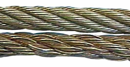
In any event, wire ropes usually announce that they are about to break. A series of individual wire breaks can be heard. These are likely to go on over several seconds and continuing for up to ten minutes before ultimate failure. Therefore, if operatives understand the warning signals, expensive incidents could be avoided.
Figure 2 shows two pieces of the same rope, the bottom portion quite clearly shows a progression of wire breaks. The operator was able to put the load down before disaster struck. The root cause of this fault was core deterioration brought about by internal corrosion.
To answer the other question on accountability, the list is extensive. Usually the first suspect is the wire rope manufacturer and that may be where the problem lies, but very often that is not the case. What if you were supplied the wrong rope for the application? Maybe you ordered the wrong rope or your buyer bought it from a cheap unapproved manufacturing source.
Perhaps your supplier is responsible, maybe he provided you with a rope that was produced to the wrong specifications. Would you know the difference? Perhaps you were sold a rope that had been stored in the suppliers or manufactures stock for a number of years and, whilst it was there, it hadn’t been properly maintained. Maybe the rope had been badly handled or installed incorrectly. The list of possibilities is endless.
In 1999 a ropeway in the French Alps snapped causing 21 deaths. In 2003, a ropeway wire rope snapped and 7 people died and a further 42 were injured. In 2007 a crane wire rope snapped at New Delhi’s metro, the entire structure tumbled down crushing workers underneath, six people were killed and 13 more were injured. In 2009 26 people were killed and 5 people were injured when a rope failed in a mine and a further 6 people were injured when a lift rope broke inside London’s Tower Bridge.
If you find yourself in the unfortunate situation after the unthinkable premature failure of a wire rope, then you might like to know that there are independent analytical services capable of determining probable cause. One of these is Doncaster Analytical Services Ltd (DAS), they have an independent metallurgical laboratory providing factual analysis and testing of wire rope for any reason (contact Mr Shui Lee, Technical Director, Tel +44(0)1302 556063, email: shui.lee@doncasteranalyticalservices. com).
You do not need a wire rope to fail in order to learn. Careful analysis of discarded ropes can also give you valuable information about your application, the way it operates, and the rope you have been using.
Based on this information, a trained, skilled and experienced inspector will be able to advise on a better crane or wire rope design, or to an improvement in maintenance procedures and safety.
Safety should be the top concern of anyone employed in rigging. When working a job where so many lives could be cut short due to carelessness, there is no excuse for laziness or distraction. Rigs should be inspected thoroughly for any potential areas of breakage. It is important for employees to gain a fluency in the causes of wire rope damage and failures so they can spot areas of weakness and fix them before they grow into a dangerous problem.
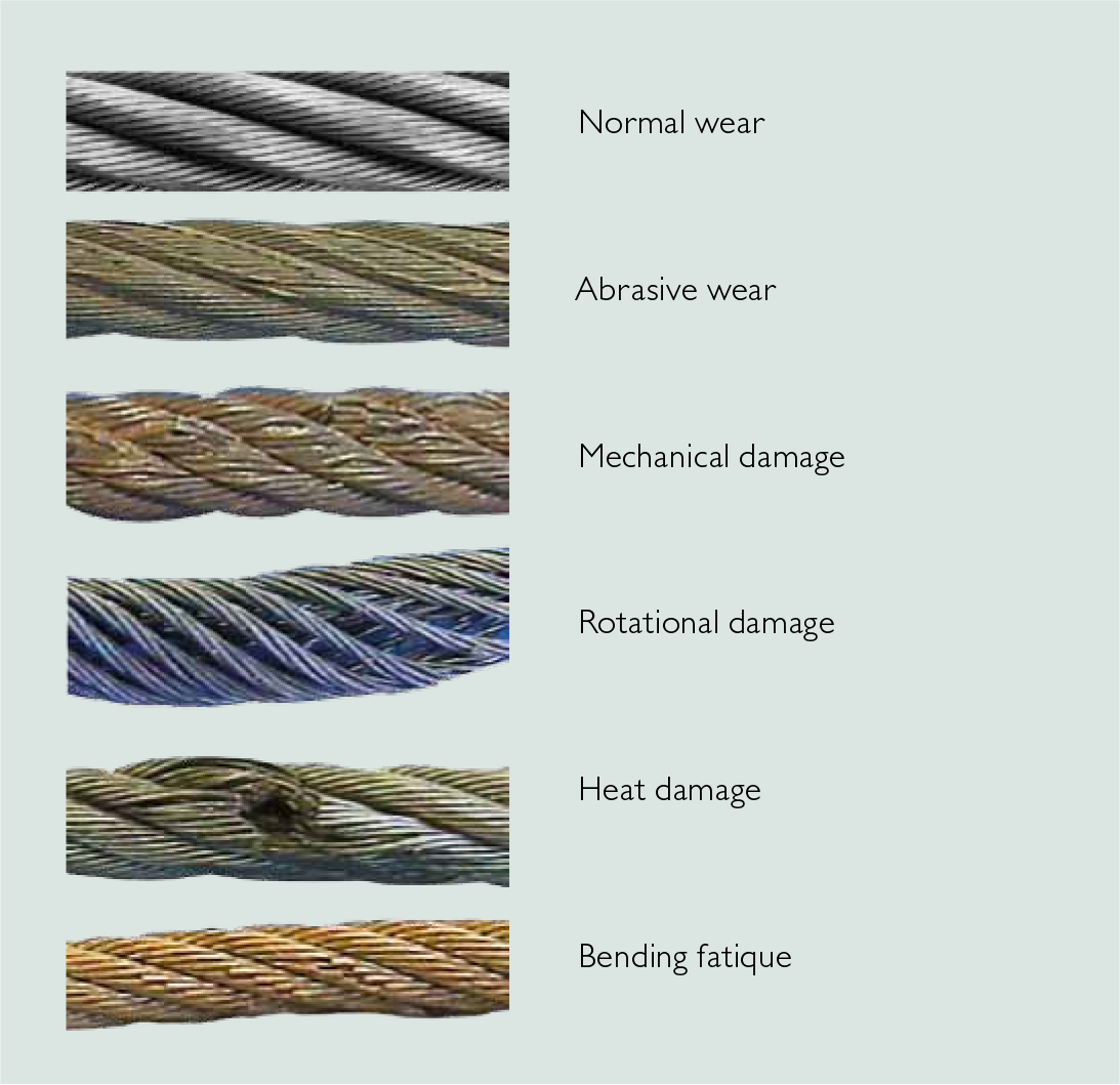
Corrosion issues in wire ropes are one of the most difficult causes of wire rope damage and failures to identify, which is why it is one of the most dangerous. Wire rope failures due to corrosion are typically the result of poor lubrication. You can measure some amount of the lubrication by looking at the pitted surface of every individual rope, but this tells us little of the damage done to the core. Since it is difficult to identify the full spectrum of corrosion, this break stands apart as mysterious and deadly.
Abrasion-caused failure occurs when the wire rope has been damaged by irregular contact with hoist sheaves and drums or when it awkwardly rubs against an object such as shelving or a crane girder. It is also often caused by poorly grooved drums and sheaves. You know the wire ropes have experienced abrasions when the wire ends are worn thin.
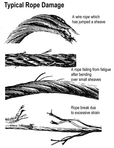
When hoist ropes go through repetitive bending over sheaves, cracks will eventually develop in the individual wires. Sections of the wire that move over the sheaves develop the worst fatigue. The damage can often be seen by the naked eye. Whenever one broken wire appears due to fatigue, more will follow. Since these issues are essentially the result of wear and tear on the rope wire, they are considered a normal part of operating a crane.
Being fluent in safety measures is just as valuable to an employer as competency with cable rigging hardware. People who know how to spot areas for potential failures can keep themselves and their coworkers secure, which saves time, money, and even lives.
Hoisting loads with a wire rope is a simple operation. Hook it up; lift it. Turns out, it’s more complicated than it appears. The details of setting up, inspecting, and maintaining lifts with wire ropes are not complicated, but are critical. A lift that goes awry is dangerous. A bad lift puts workers at risk. In this article, we discuss the causes of wire rope failure and how to avoid them.
Abrasion breaks are caused by external factors such as coming into contact with improperly grooved sheaves and drums. Or just hitting against some object during operation. Worn, broken wire ends is the result of an abrasion break. Common causes of abrasion breaks include:
Core slippage or protrusion is caused by shock load or improper installation of the wire rope. Excessive torque can cause core slippage that forces the outer strands to shorten. The core will then protrude from the rope. Wire ropes designed to be rotation-resistant should be handled carefully so as not to disturb its lay length.
Corrosion breaks cause pitting on the individual wires that comprise the rope. This type of damage is caused by poor lubrication. However, corrosion breaks are also caused by the wire rope coming into contact with corrosive chemicals, such as acid.
There are many ways the strands of a rope can be crushed or flattened. Improper installation is a common cause. To avoid crushing, you’ll want the first layer of the wire rope to be very tight. You’ll also need to properly break-in a new wire rope. Other causes of crushing include cross winding, using a rope of the wrong diameter, or one that it too long.
Cracks to individual wires are caused by fatigue breaks. Fatigue breaks happen because the wire rope is being bent over the sheave over and over again. In time, the constant rubbing of the wire rope against the sheave or drum causes these breaks. Sheaves that are too small will accelerate fatigue breaks because they require more bending. Worn bearings and misaligned sheaves can also cause fatigue. A certain number of broken wires is acceptable. The worker responsible for equipment inspection prior to use should know the American Society of Mechanical Engineers (ASME) standard for wire ropes. The ASME standard determines whether the wire rope must be replaced. (https://www.asme.org/)
Selecting the right wire rope for the job is critical. There is never a perfect rope. For example, you will need to make a tradeoff between fatigue resistance and abrasion resistance. There are several aspects to wire rope design to consider, including:
In general, the proper wire rope will have a strength rating high enough to handle the load. (Strength is rated in tons.) It can handle the stress of repeated bending as it passes over sheaves or around drums. How you attach the rope in preparation for the lift matters and should only be handled by properly trained workers.
The wire rope (and all the equipment involved in a lift) should be fully inspected prior to the lift. The worker performing the inspection should be well-versed in the types of damage that can cause a wire rope to fail. Using a checklist is highly recommended. This will ensure that the inspection is complete. Worker and supervisor signoff will increase accountability. Of course, the wire rope must be maintained according to the manufacturer’s instructions.
How a wire rope is stored, the weather conditions in which it is used, and how they are cleaned all affect its useful life. The Occupational Safety and Health Administration (OSHA) provides these recommendations: (Source: https://www.osha.gov/dsg/guidance/slings/wire.html)
Preventing wire rope failures starts with selecting the right one for the job. When in doubt, talk with your local equipment dealer. Be prepared to discuss your specific job requirements. A thorough inspection of the wire rope prior to using it is critical. Finally, properly store your wire rope. The selection, inspection, and care of wire rope is key to job safety.

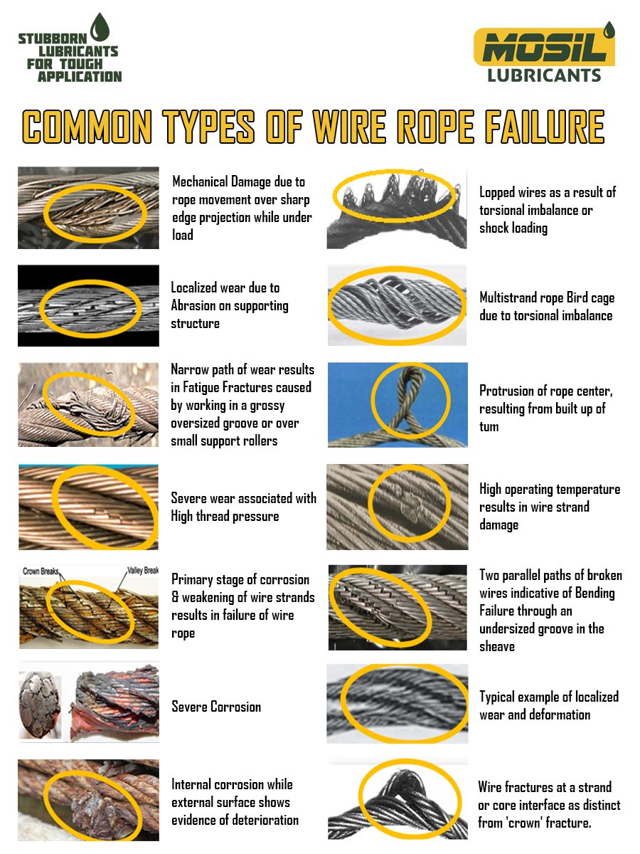
Mechanical damage caused by the rope contacting the structure of the crane on which it is operating or an external structure—usually of a localized nature.Generally results from operational conditions.
Note—Rotation Resistant ropes are designed with a specific strand gap which may be apparent on delivery in an off tension condition. These gaps will close under load and will have no effect on the operational performance of the rope.Check sheave and drum groove radii using sheave gauge to ensure that they are no smaller than nominal rope radius +2.5%—Bridon recommends that the sheave and drum groove radii are checked prior to any rope installation.
Check if the rope has been cut “on site “ prior to installation or cut to remove a damaged portion from the end of the rope. If so, was the correct cutting procedure used? Incorrect cutting of Rotation Resistant, low rotation and parallel closed ropes can cause distortion in operation.
Wire breaks usually resulting from crushing or abrasion.Check tension on underlying layers. Bridon recommends an installation tension of between 2% and 10% of the minimum breaking force of the wire rope. Care should be taken to ensure that tension is retained in service. Insufficient tension will result in these lower layers being more prone to crushing damage.
“Pigtail” or severe spiralling in rope.Check that the sheave and drum diameter is large enough— Bridon recommends a minimum ratio of the drum / sheave to nominal rope diameter of 18:1.
Two single axial lines of broken wires running along the length of the rope approximately 120 degrees apart indicating that the rope is being “nipped” in a tight sheave.Check sheave and drum groove radii using sheave gauge to ensure that they are no smaller than nominal rope radius + 2.5%—Bridon would recommend that the sheave / drum groove radii are checked prior to any rope installation.
One line of broken wires running along the length of the rope indicating insufficient support for the rope, generally caused by oversize sheave or drum grooving.Check to see if the groove diameter is no greater than 15% greater than the nominal rope diameter.
Fatigue induced wire breaks are characterized ends by flat on the broken wires.Bending fatigue is accelerated as the load increases and as the bending radius decreases. Consider whether either factor can be improved.
Fatigue induced wire breaks are characterized ends by flat on the broken wires.Bending fatigue is accelerated as the load increases and as the bending radius decreases. Consider whether either factor can be improved.
Localized fatigue breaks indicate continuous repetitive bends over a short length. Consider whether it is economic to periodically shorten the rope in order to move the rope through the system and progressively expose fresh rope to the severe bending zone. In order to facilitate this procedure it may be necessary to begin operating with a slightly longer length of rope.
Broken rope—ropes are likely to break when subjected to substantial overload or misuse particularly when a rope has already been subjected to mechanical damage.
Corrosion of the rope both internally and/or externally can also result in a significant loss in metallic area. The rope strength is reduced to a level where it is unable to sustain the normal working load.Review operating conditions.
Wave or corkscrew deformations normally associated with multi-strand ropes.Check sheave and drum groove radii using sheave gauge to ensure that they are no smaller than nominal rope radius +2.5%—Bridon recommends that the sheave / drum groove radii are checked prior to any rope installation.
Rope accumulating or “stacking” at drum flange— due to insufficient fleet angle.Review drum design with original equipment manufacturer—consider adding rope kicker, fleeting sheave, etc.
Check tension on underlying layers—Bridon recommends an installation tension of between 2% and 10% of the minimum breaking force of the wire rope—Care should be taken to ensure that tension is retained in service. Insufficient tension will result in these lower layers being more prone to crushing damage.
Review rope selection. The smooth surface of Dyform wire ropes gives better contact with drum and sheaves and offers improved resistance to “interference” between adjacent laps of rope.
A customer recently contacted us to reorder the wire rope component of their Electrolifttwin hook monorail hoist. While the hoist was only a year old, they had replaced the wire rope twice within six months. They sent a picture of the damaged rope and asked for reasons why the wire rope was failing.What’s killing my wire rope?
It’s important to note that the wire rope used for hoists and overhead cranes is specially made of extra flexible Improved Plow Steel (IPS). It’s considered superior in durability and tensile strength (bending) to standard, everyday wire rope.
When properly sized and lubricated, a wire rope should last for years, even with frequent use. Wire rope hoists are recommended for heavy duty applications, high frequency usage and where long lifts are needed.
The Answer:Most likely, there’s a problem with how the hoist is operated. Wire rope failure is almost always due to operator error. By design, hoist hook blocks must be raised and lowered straight up and straight down, and the wire rope cable wraps around the drum, within the grooving, in one layer. In the course of picking up a load, if the operator side pulls the rope by more than about three degrees from vertical, the wire rope will jump the drum’s grooves.
Once the grooves are jumped, the operator must realize the error and stop using the hoist immediately. To correct the issue, the load must be lowered and the wire rope must be allowed to return it to the correct drum grooves. If the operator continues to use the hoist with the wire rope piled up at one end of the drum, the rope gets pinched and the cable can become damaged. Also in the course of usage, if the cable goes slack and the wire rope jumps over the drum guard, it could get caught between the drum and the shaft, and the wire rope could fail.
To prevent this problem, we recommend operator training classesand regular inspection of the unit. Every shift should start with an examination of the rope by lowering the hook all the way down. If the rope is damaged, including even one strand broken, stop the process and get the rope replaced. We recommend keeping spare ropes in stock to avoid downtime and
Wire rope and cranes are joined at the hip when endeavoring to lift, move or transport materials. For centuries the combination of rope (sisal, manila, vegetable, steel, synthetic…) and a winching system have stirred the imagination of engineers and other interested persons in aiding the lifting and handling of heavy objects.
Giant strides in the development of the “crane and rope” system have led to unimaginable progress in leaps and bounds in today’s world. One thing that has remained constant over many decades is the fact that all types of rope used on cranes do eventually wear our and must be replaced.
This article focuses on actual wire rope failures, or near failures, that have occurred. The fact that all wire ropes on a crane will deteriorate over periods of operation is a universal truth, but the useful service life of wire rope will vary according to applications, operating conditions, working environment, type of crane, crane operator and other factors. Therefore, it is a necessity that proper inspection, maintenance and retirement criteria be firmly established to achieve safe and efficient working conditions.
When a wire rope on a crane fails, traumatic consequences will likely follow. At the very least, equipment damage and downtime will ensue, but more importantly lives many times are lost. These wire rope failures are mostly, not because of structural causes, but from human error, neglect, lack of training or not following known instructions. In my experience, the three main reasons for wire rope failures on cranes are misuse, abuse and overuse.
A failure analysis of a broken multi strand 71mm steel wire rope used in the main towing winch was carried out. The wire rope was failed during a bollard pull test. The wire rope was a new one and had failed during the first use. The wire rope was in IWRC/ RHO 6X41 constructions. Fig.1 shows the typical cross section of the wire rope. The failure investigation is performed by chemical and metallurgical examinations.
(ii) the uniformity and cleanliness of the microstructure of the rope steel and the effect of microstructure on crack initiation and propagation, and
1) Chemical analysis of steel wire rope is presented in Table 1. The analysis showed that it is made of high carbon steel corresponding to AISI 1074 grade, and galvanized with zinc to resist corrosion.
2) The microstructure observed under optical microscope and is shown in Figs. 2. It was typical of a drawn ferrite–pearlitic steel wire with heavily cold worked micro structure. Further examination of microstructure of the failed wires did not indicate any sign of metallurgical problems such as de- carburized layer, nonmetallic inclusions, or martensite formation. In addition, the wires were free from any sort of corrosion and pitting. Therefore, corrosion had no role in the failure of wires.
4) Table 3 represents the tensile values of the wire. The result indicates relatively less value comparing the metallographic results and the mill test certificate supplied by the Client. Figs. 3 showing Stress- Strain during tensile testing of the wire
The high hardness values, chemical composition, and the pearlitic structure of wires indicating that this is a type of extra extra improved plow steel (EEIPS) grade wire ropes. These types of wires have typically higher load-bearing capacity as compared with other grades. They are considered as heavy-duty wire ropes. The minimum tensile strength of EEIPS is 2160 N/mm2. (Ref. API Spec 9A)
5) The fractured ends of group of wires were visually inspected. Majority of wires failed in shear, and the remaining had cup-and-cone fracture, some of which are shown in Fig. 4.
Fractographs of broken wires in the form of cup and cone and shear are shown in Fig. 5 and Fig.6. Tensile overload fracture occurs when the axial load exceeds the breaking strength of the wires. This type of fracture usually appears in ductile manner, either in the form of cup and cone or in shear mode. In the former case, there is a reduction at the fracture which is called necking, whereas in the case of the latter, fracture surface is inclined at 45degree to the wire axis. In both cases, ductile dimple formations are clearly observed and confirm the tensile overloading of wires.
Every wire rope failure will be accompanied by a certain number of tensile over load breaks. The fact that tensile overload wire breaks can be found therefore necessarily mean that the rope failed because of an overload. The rope might have been weakened by fatigue breaks. The remaining wires were then no longer able to support the load, leading to tensile overload failures of these remaining wires.
Only if the metallic area of the tensile overload breaks and shear breaks combined is much higher than 50% of the wire rope’s metallic cross section is it likely that the rope failed because of an overload.
Shear breaks are caused by axial loads combined with perpendicular compression of the wire. Their break surface is inclined at about 45degree to the wire axis. The wire will fail in shear at a lower axial load than the pure tensile over load.
If a steel wire rope breaks as a consequence of jumping a layer or being wedged in, a majority of wires will exhibit the typical 45degree break surface.
In the instant case the wire rope was failed at 100 Ton or even less. As the breaking load of the wire rope is 353 Tons, there is no reason for a tensile over load breaks in an axial direction and that too considering the fact that the wire rope was failed during a bollard pull test. Fig. 7 shows the maximum stress generations in the wire rope at 100 Ton under normal bollard pull test. More over the metallurgical investigation is also not suggesting for any factors that fostering an axial overload failure.
The failure of the wire rope was studied in detail. In order to investigate the problem metallurgical and mechanical post failure analyses were performed. The wire rope was made of AISI 1074 grade steel, and it was a type of EEIPS. The microstructure was composed of severely deformed and elongated ferrite–pearlite, and no other phase formation or nonmetallic inclusions could be detected. The morphologies of fractured surfaces indicated that the wires were mainly failed in shear mode and few in tensile mode. Owing to galvanized coating, the wires were free from corrosion.
The tensile strength of the wire material is less than the required value. The required tensile strength of EEIPS is 2160 N/mm2 and the obtained value is 2059 N/mm2. But this factor is not a reason for the current failure of the wire rope. The said point is substantiated by the following:
It is concluded that the wire rope was failed due to shear breaks. Shear breaks were caused by high axial loads combined with perpendicular compression of the wire. It is worthwhile to note that the rope was failed in its first usage. The shear break is linked to the lapses during the installation/ spooling of the wire rope.
b) Lack of pretension of lower rope layers during spooling. In the absence of proper pretension the upper layers might be pulled in between the lower layers during loading.
c) Under high tension, the rope tends to be as round as possible. With no load, a rope can be deformed and flattened much easily. Highly tensioned upper layers will therefore severely damage loose (and therefore vulnerable) lower layers.
Unfortunately, many phone calls into ITI Field Services begins this way, “We have had an incident with a wire rope and we believe the rope failed. How do we determine the cause of failure?”
Fortunately, the calls come in because wire rope users want to determine cause of failure in an effort to improve their crane, rigging and lifting activities.
A wire rope distributor received a hoist rope and sockets from a rubber-tired gantry. The rope and sockets were returned by the customer who believed the rope and sockets failed. The distributor hired ITI Field Services to conduct an analysis on the rope and sockets to determine the cause of the failure and to produce written documentation.
Based on the findings of the examination, fatigue-type breaks in the wires indicated that the wire rope lost significant strength due to vibration. There was no indication that the rope was overloaded. The poured sockets showed no evidence of abnormalities in the pouring method, wire zinc bonding length or the materials used in the speltering process. The conclusion of the inspection is that rope failed due to fatigue.
Wire rope examination is just one of the many services that is offered by ITI Field Services. ITI has some of the most highly-regarded subject-matter experts in the crane and rigging industry with experience in performance evaluations, litigation, accident investigations, manual development and critical lift planning reviews.
But on one particular day in early May of 2009, it wasn’t a boom reaching toward the big Texas sky that was causing people to stop and stare; it was one that was lying in a heap just beside the water, lattice sections bent and lacings twisted into mess of mangled steel and frayed wire rope. “I got the call to investigate the cause of loss on a Manitowoc 888 that was being used to drive underwater pilings at a dock in Port Isabel,” says JR Bristow, of Bristow Truck and Equipment Specialists, an organization based in Ridgewood, NJ that provides failure analysis and appraisals, among other things, for heavy equipment. “The operator was hoisting the boom when it just sort of gave out and crashed to the ground. No one was hurt, but the boom was in bad shape. The initial reserve was set at $500,000.”
Though a half million dollars wasn’t a total loss – the crane was valued at $1.5 million – it was a pretty hefty price to pay for something that, as it turned out, could have been avoided. On lattice-type cranes, booms are raised and lowered using boom hoist wire rope, and when that wire rope shows surface wear or corrosion, or worse, has broken wires within the rope strand, it can fail. It’s usually just a matter of time.
The subsequent investigation that followed revealed that the wire rope used to hoist the boom of the Model 888 had been in an out-of-service condition for quite some time, due to lack of proper lubrication.
“An examination of the failed boom hoist wire rope revealed that the wire rope had gone without the proper lubrication, which was the responsibility of the insured per the attached lease agreement,” Bristow remembers. “I also noted significant broken wires within the rope strands at an average of six to 12 per strand lay. Clearly, if the insured had performed a daily inspection of the boom hoist wire rope as required, that incident would not have happened.”
The broken strand condition that Bristow observed was caused by load cycles that occurred during boom up and boom down functions that were part of the daily operation of the crane. Simultaneous compression and expansion of the wire rope usually occurs as it travels over the hoist sheaves, and that causes the gradual deterioration of the strand wires.
Like many other segments of the crane and rigging industry, the nuances of wire rope are complicated and varied. Considerable time, money and resources have been invested in new technology, new inspection suggestions and new manufacturers. And rightly so. As was the case in Bristow’s example earlier, there’s quite a bit at stake in terms of both human capital and equipment cost.
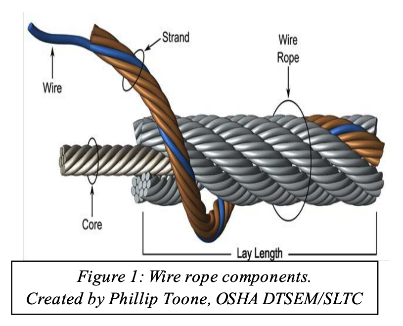
Python High Performance wire rope, a wire rope manufacturer that has produced a number of resources to assist people in understanding and ultimately purchasing wire rope, clarifies the structure of wire rope on its website www.pythonrope.com.
Python’s site explains that a typical wire rope can contain hundreds of individual wires. These wires are fabricated and formed to operate at close bearing tolerances to one another. When a wire rope bends, each of its many wires slides and adjusts in the bend to accommodate the difference in length between the inside and the outside bend. The sharper the bend, the greater the movement, and the greater capacity for stress on the wire rope.
While manufacturers of wire rope are many and varied, each of the wire ropes they produce have three basic components:The wires, which form the strands and collectively provide the rope strength
According to Python’s site, the greatest differences in wire ropes are found in the number of strands, the construction of strands, the size of the core and the lay direction of the strand versus the core. But what does that mean for the layperson? What should he or she look for when purchasing wire rope?
Tony Fastuca, vice president Python America & High Performance Products, says that most people buy rope based on four ideal standards. “Abrasion resistance, fatigue resistance, flexibility and strength. Those four typical standards often weigh into a purchase decision: he says. “A buyer sometimes has to give a little in one area to get a bit more in another, but a lot of buyers are looking for a good balance of those four standards.”
Whereas other products usually come with an expected lifespan, wire ropes don’t really have an average operational life. “There are records that exist of wire ropes getting two to three years of use, sometimes longer,” says Fastuca. ”But it’s about the level of wear on the rope, not the length of time it’s been in service.”
Just as the crane itself needs to undergo frequent and period inspections, the wire rope does, too. Fastuca talks of the so called “A,B,Cs” of wire rope abuse – abrasion, bending, crushing.
The principle goal of a wire rope inspection is to find potential problems before they manifest into incidents or serious accidents. Inspections should be performed slowly and methodically, with a keen eye for corrosion or broken wires or sections of rope that look questionable. Because the reality of wire rope is that it will fail if it becomes worn out, overloaded, damaged, misused or improperly maintained. It can lead to huge headaches for companies that try to take shortcuts or don’t properly maintain it – a risk that just isn’t worth taking.
The best time to troubleshoot wire rope problems is while it is operating on the equipment. Unfortunately, due to the importance of keeping equipment running, the wire rope may be taken out of service before a wire rope engineer has the opportunity to examine it. The sample is then sent back to the wire rope manufacturer for cause determination. This article outlines the approach that one manufacturer of wire rope takes with these returned samples as well as troubleshooting on site. The lessons learned from these examinations should help prevent recurring problems as well as provide the answer to some puzzling wire rope reactions.
Much like a medical examiner or coroner, the director of engineering is called upon to perform an autopsy on a wire rope returned from the field. When a sample is sent in, the sender usually believes that there was some kind of “birth defect”. Oddly enough, it is the director of engineering that issued the birth certificate (test certificate) and is now responsible for determining the cause of death.
The most important thing to receive with the rope sample is proper documentation. Rope samples are often received with no paperwork, which delays the examination. Along with the rope sample, the following information should be supplied:
• changes – this would include changes in type of work; change in rope manufacturer or construction; equipment modifications, operator, lubrication etc.
As a rule, examinations are not performed on ropes from other manufacturers. Yet many ropes are received that were made elsewhere. Generally, this is not because of misrepresentation during the supply phase, but because of poor record keeping. It is recommended to use a wire rope inspection log where the user can enter the appropriate wire rope information along with the installation date. The wire rope manufacturer’s test certificate should also be stored with the inspection log. The inspection information that is recorded on the log is extremely valuable as the user can also monitor the rate of deterioration.
In one incident a user had experienced a total boom hoist rope failure. Samples of the rope were sent back and it was quickly determined that it was made by another manufacturer. The user was surprised because it had not bought a rope from that manufacturer for over three years. The company policy was to change boom hoist ropes at least every two years. Failure occurred because the rope was way beyond normal retirement criteria. This could have been picked up from an inspection form and the accident thus prevented. Of course, proper inspection techniques would have also prevented the failure.
The first part of the examination is to verify the rope construction. The manufacturer is not verified until the rope is disassembled so the marker can be obtained. The diameter is taken and compared to the diameter recorded at manufacture. The rope’s lay length is also measured and compared to the original measurement. The rope’s exterior surface is examined for wear and corrosion. If broken wires are present, they are counted and the type and location of fracture is noted and recorded.
Sometimes there may be deformation in the rope structure. This could be localised kinks, severe wire displacement or possibly a corkscrew or wave. If the latter condition is noted, the amplitude of the deformation and length of affected area is recorded. The rope is also examined for thermal damage. The rope is then disassembled and the internal rope is inspected much like the rope’s exterior, except that the degree of wire indentations (notching) is also examined.
All the findings are like clues that when put together with the background information determine the cause of failure. Many of the samples received have completely failed and should have been removed from service long before the time of failure. It is evident that they were not inspected thoroughly or in a timely manner. Other failures happened suddenly, like a jumped sheave or from a shock load. These are not inspection problems but either machine or operator related. These latter examples usually arrive in a condition that makes it obvious what has happened.
An example of this is shown in Figure 1 which shows a rope that has operated around an extremely small radius, perhaps from jumping a sheave. Operating around such a small radius has caused this coil like condition.
Figure 2 is an example of a rotation resistant rope from a pedestal crane that has experienced a shock load, resulting in the inner rope popping out suddenly.
Sometimes, a wire rope failure has to be investigated at the scene. Figure 3 shows a wire rope that has completely failed. On closer examination, the majority of the wire ends were cut in shear with some broken in tension. The fact that most of the wire fractures were in shear indicates that a sharp object had severed the rope.
Upon closer investigation, the sheave shown in Figure 4 appears to be the murder weapon. The rope evidently looped out of the sheaves somehow and when put back under tension straddled the sheave and was cut by the sharp edge.
If the rope is still operating on the equipment there is an opportunity to see the rope problem and how it relates to its environment. When troubleshooting in-situ, no assumptions are made. Essentially, some basic steps are followed that should provide all the information needed to make a cause determination.
• check the condition of the rope related equipment: drum – general condition drum grooves – radius and pitch kicker plates or wear plates – condition and position sheave grooving – correct shape and size sheaves – free to rotate and in good condition rope guards – correctly fitted and in good condition wear plates or rollers – condition
A simple trick is to paint the damaged area and see where the affected area is positioned during the operating cycle. Figure 5 is an example of a rope that was at the flange in the layer change transition point. The rope should have been retired before it made it to this condition. A simple drum end rope cut earlier in the rope life would have moved the rope before it became a problem. Slip and cut programmes extend rope life and should be considered for all drum applications (especially smooth face drums). Information gathered should determine the cause of the problem. The most common problems are:
Before contacting the manufacturer, review publications like the Wire Rope Users Manual published by the USA’s Wire Rope Technical Board. Samples of various problems are illustrated which can help the user make an immediate determination. If the cause cannot be identified, take down all the information as covered earlier and ask the original manufacturer for assistance. No matter what has happened to the wire rope, it leaves behind undeniable clues that when matched with site information provides the investigator with the answer to the problem. Wire rope always tells the story.
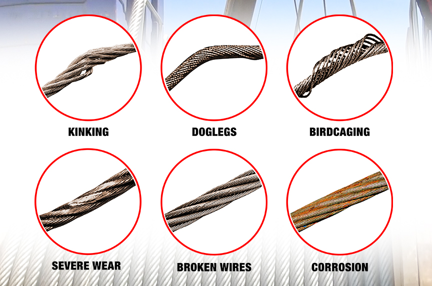
Wire Rope is an item often found on Wire Rope Cranes. Unfortunately, though these wires are not unbreakable and can/will succumb to the pressure of constant use and may potentially snap when in use. Which is why it is important to know what to look out for in an unsafe wire rope, the Government of Canada recommends a visual inspection of the wire before each use, but full inspections should be undertaken by a trained professional periodically. This article will cover what causes wire ropes to break, what your professional inspector will do to ensure your rope is safe and what you can look out for when completing your frequent inspection to ensure the rope is safe to work with.
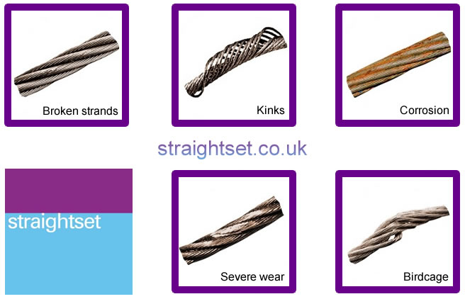
When you hear the term wire rope you may picture in your mind a metal and seemingly unbreakable rope, and through wire ropes, can and will stand up better than many other rope types it is unfortunately not unbreakable. Some things that can cause a wire rope to break include:
Kinks caused by improper installation of a rope, sudden release of a load or knots that were made to shorten a rope can cause the rope to become compromised
Many of these causes can be minimized by the use of proper crane design and rope maintenance procedures, most of these causes though are unavoidable and are considered to be part of a normal rope life. The two main causes that are considered unavoidable are crushing and internal and external fatigue.
Many wire ropes are subject to a lot of repetitive bending over a sheave, which causes the wire to develop cracks in its individual wires. These broken wires often develop in the sections that move over sheaves. This process will become escalated if a rope travels on and off of a grooved single layer drum, which causes this to go through a bending cycle. Tests in the past have shown that winding on a single layer drum is equal to bending over a sheave because it causes similar damage.
Fatigue breaks often develop in segments as stated before these segments are usually the part of the rope surface that comes into direct contact with a sheave or drum. Because this is caused by external elements rubbing, oftentimes these breakages are external and visible for the eye to see. Once broken wires start to appear, it creates a domino effect and quickly much more will appear. Square ends of wires are common for fatigue breaks. These breaks are considered a long-term condition and are to be considered part of the normal to the operating process.
Internal Breaks,these breaks can develop over time-based upon the loading of the hoist. Many ropes are made of a torque-balanced multi-strand design, which comprises of two or more layers of strands. A torque balance is created in multi-strand ropes, by layering the outside and inside ropes in opposite directions. Multi-strand ropes offer much more flexibility and have a more wear-resistant profile. Though the wires in these ropes touch locally and at an angle, which causes them to be subject to both the effect of radial load, relative motion between wires and bending stresses when bent on sheaves or drums.
Nicking and fatigue patterns such as the ones discussed before occur in Independent Wire Rope Cores or IWRC ropes. IWRC ropes have outer wires of the outer strands, which have a larger diameter than the outer core strands. This helps to minimize inner strand nicking between the outer strands of the IWRC. The outer strands and the IWRC strands are approximately parallel. Often their neighbouring strands support these outer strands while the outer IWRC wires are relatively unsupported.
With these geometrical features it allows for the wire to fluctuate under tensile loads, the outer IWRC wires are continuously forced into valleys in between the outer strand wires and then released. This system results in secondary bending stresses which leads to a large number of core wires with fatigue breaks. These breaks are often close together and form in groups. This eventually leads to the IWRC breaking or completely disintegrating into short pieces of wire that lay, half a length long. This condition is often called complete rope core failure.
It is as the IWRC fails, and the outer strands lose their radial support then valley breaksform. Valley breaks occur when the outer strand wires bear against each other tangentially. This results in interstrand nicking, which restricts the movement of strands within the rope; without the freedom to move, secondary fatigue breaks occur in the outer strands, which will develop a stand tangent points. These breaks occur in the valleys between the outer strands hence why they are called valley breaks.
So to go over what we just learned, internal broken wires occur often in ropes that are operated with large diameter sheaves and high factors of safety. These breakages can occur when a reeving system incorporates sheaves lined with plastic or all plastic sheaves; these sheave units offer more elastic support than their steel counterparts. Which causes the pressure between outer wires and sheave grooves to be reduced to the point where the first wire breaks will occur internally.
If a section of a rope travels on and off of a grooved multi-layer drum, then it goes through what is called a bending cycle. The bending cycle occurs by a section of rope spooling in the first layer and is bent around the smooth drum surface, but when the second layer rolls around the rope section in the first layer will be spooled over. This causes the first layer to become compressed and damaged on the upper side by the second rope layer. With continued spooling the rope layers in the second and higher layers will, in turn, be damaged on both sides during contact with their neighbouring rope layers. This damage is caused both by the compression of the rope and by the rope laying on a rough surface.
Accelerated wear occurs where the point of the rope is squeezed between the drum flange and the previous layer. Often times the slap of rope at the crossover points causes peening, martensitic embrittlement and/or wire plucking, further associated rope damage is caused when the rope crosses over from layer to layer on a drum.
Also, if the lower wire rope areas where not spooled under sufficiently high tension the lower wraps can become displaced by the additional rope sections which would allow for these new rope sections to slide down in between them, which will lead to severe rope damage.
Many regulators have decided that the Statutory Life Policy be overly wasteful and they tend to use the Retirement for Clause Policy. A wire rope deteriorates slowly over its entire service, but to be aware of the state of deterioration, a wire rope must be periodically inspected. Moderate deterioration is normally present, and low levels of deterioration do not justify retirement. Which is why you have wire rope inspections to monitor the normal process of deterioration. This ensures that the rope can be retired before it can become dangerous. Besides, these inspections can detect unexpected damage or corrosion on the wire rope which will allow you to take corrective actions to ensure the longevity of the wire rope.
This system is useful for detecting external rope deterioration. To use this approach, the inspector will lightly grab the rope with a rag. The inspector then glides the cloth over the rope. Often times external broken wires will porcupine (stick up). When the rope moves along the wire it will be snagged on the broken wire. The inspectorwill then stops dragging the cloth along the wire and visually inspects the condition of the wire.
Frequently broken wires often do no porcupine, which is why a different test procedure must be utilized. This test involves moving along the rope two or three feet at a time and visually examining the rope. This method though can become tiresome because oftentimes the rope is covered in grease and many internal and external defects will avoid detection through this method.
Another method involves measuring the wire ropes diameter. This involves comparing the diameter of the current rope to the original rope’s diameter. Changes in the diameter of the rope indicate external and/or internal rope damage. This method is not perfect because many different wire breakages damages do not change the diameter of the rope.
You can also check for several visible signs of distributed losses of the metallic cross-sectional area. This is often caused by corrosion, abrasion and wear. To internally check for damage, you can insert a marlinspike under two strands and rotate it to lift the strands and open the rope.
Visual inspections are often not well suited for the detection of internal rope damage. This means that they have limited value as the only means of wire rope inspection. Though visual inspections do not require special machines. When completed by a knowledgeable and experienced rope examiner through visual inspections can be valuable tools for evaluating rope degeneration.
Electromagnetic Inspections or EM gives a detailed insight into the exact condition of a rope. EM is a very reliable inspection method and is a universally accepted method for inspecting wire ropes for mining, ski lifts and other similar industries. There are two distinct EM inspection methods, which have been developed to classify defects called Localized-Flaw (LF Inspection) and Loss-of-Metallic-Area Inspection (LMA Inspection type)
LF Inspection is similar to the rag-and-visual method. This inspection method is suited primarily for finding localized flaws, such as broken wires. Which is why small hand-held LF instruments are called electronic rags.
Electromagnetic and visual wire rope inspection methods are like peanut butter and jelly or cookies and milk they are the perfect combination, and both are essential for safe rope operation. Which is why both methods are often used to ensure maximum safety.
A program that involves periodic inspections is extremely effective. To establish baseline data for future inspections, a wire rope inspection program should begin with an initial inspection after a break-in period. Then the inspections should follow at scheduled intervals, with documentation of the ropes deterioration over its entire service life.
For multi-strand ropes often times visual inspections are ineffective which is why statutory life policy for a ropes retirement is often adopted. This means that these ropes are often discarded long before they should be meaning millions of dollars’ worth of perfectly good wire ropes are being thrown away annually.
Some people have suggested that non-rotating ropes should not be used if cranes use a single layer winding on a drum. Following this line of thought, this would mean multi-strand ropes should be used only when winding on multi-layer drums. This would cause wires to break the surface faster than internal wire damage can occur, these non-rotating wire ropes will be replaced long before internal fatigue can set in.
When internal broken wires are the problem electromagnetic rope testing can be the solution. Though there are some factors one needs to take into account such as certain regulations require rope retirement when a certain number of broken wires per unit of rope length exceed a set limit. This discard number that is specified in retirement standards refers solely to external wire breaks. This means the condition of a wire rope with internal breaks is therefore left up to the inspector.
Though you also need to take into account detailed detection and quantitative characterization of internal broken wires in ropes with many breaks and cluster breaks could be a problem. These difficulties are caused by the fact that electromagnetic wire rope can be influenced by several parameters such as:
Clusters of broken wires can cause an additional problem because the relative position of broken wires concerning each other within the rope is not known
Broken wires with zero or tight gap widths are not detectable by electromagnetic inspection because they do not have a sufficient magnetic leakage flux.
When you consider all of this you can quickly realize that you can only estimate the number of broken wires that have formed on a wire rope. You can use the LF trace for the detection of broken wires, though unfortunately it is not quantitative so it cannot be used to estimate the number of broken wires. Though it is good to note that if any internal broken wires are present an LMA trace will show rapid relatively small variations of a cross-section.
An electromagnetic inspection will help to enhance the accuracy and reliability of the inspection, by combining visual and EM methods they will be able to detect deterioration at the earliest stages. The inspections can be then used as an effective preventive maintenance tool. For example, the inspector early on detects corrosion, and you immediately apply the corrective action of improving the lubrication of the wire rope.
Wire ropes should be inspected by a certified inspector when installing it, and periodically throughout its life cycle. A wire rope should go through a quick, but thorough inspection every day that you use it at the beginning and end of each shift and you should keep records of all inspections. Ensure that your certified wire rope inspector uses a combination of visual inspection methods and electromagnetic inspection methods because this will ensure the optimum safety and longevity of the rope. This is especially true for ropes that are more likely to develop internal broken wires, and inspections completed by a certified inspector is the best way of having a preventive maintenance program and extending the life of your wire rope.
Queensland Division of Workplace Health and Safety, “Non-rotating hoist wire ropes, multi fall configurations, Health and Safety Alert,” http://www.whs.qld.gov.au/alerts/97-i-5.pdf
Verreet, R. “Wire rope damage due to bending fatigue and drum crushing,” O.I.P.E.E.C.(International Organization for the Study of the Endurance of Wire Rope) Bulletin 85, June 2003, Reading (UK), ODN 0738, pp. 27-46.


 8613371530291