
wire rope failure osha pricelist
A competent person must begin a visual inspection prior to each shift the equipment is used, which must be completed before or during that shift. The inspection must consist of observation of wire ropes (running and standing) that are likely to be in use during the shift for apparent deficiencies, including those listed in paragraph (a)(2) of this section. Untwisting (opening) of wire rope or booming down is not required as part of this inspection.
Significant distortion of the wire rope structure such as kinking, crushing, unstranding, birdcaging, signs of core failure or steel core protrusion between the outer strands.
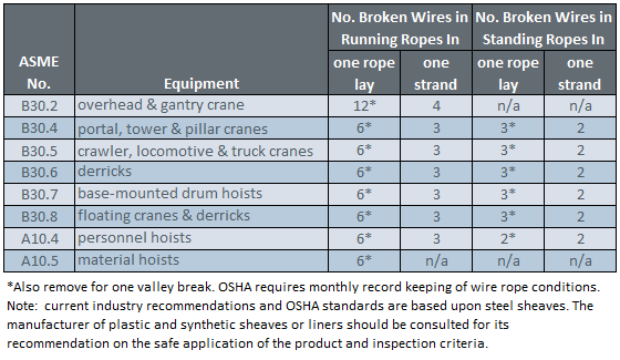
In running wire ropes: Six randomly distributed broken wires in one rope lay or three broken wires in one strand in one rope lay, where a rope lay is the length along the rope in which one strand makes a complete revolution around the rope.
In rotation resistant ropes: Two randomly distributed broken wires in six rope diameters or four randomly distributed broken wires in 30 rope diameters.
In pendants or standing wire ropes: More than two broken wires in one rope lay located in rope beyond end connections and/or more than one broken wire in a rope lay located at an end connection.
If a deficiency in Category I (see paragraph (a)(2)(i) of this section) is identified, an immediate determination must be made by the competent person as to whether the deficiency constitutes a safety hazard. If the deficiency is determined to constitute a safety hazard, operations involving use of the wire rope in question must be prohibited until:
If the deficiency is localized, the problem is corrected by severing the wire rope in two; the undamaged portion may continue to be used. Joining lengths of wire rope by splicing is prohibited. If a rope is shortened under this paragraph, the employer must ensure that the drum will still have two wraps of wire when the load and/or boom is in its lowest position.
If a deficiency in Category II (see paragraph (a)(2)(ii) of this section) is identified, operations involving use of the wire rope in question must be prohibited until:
The employer complies with the wire rope manufacturer"s established criterion for removal from service or a different criterion that the wire rope manufacturer has approved in writing for that specific wire rope (see § 1926.1417),
If the deficiency is localized, the problem is corrected by severing the wire rope in two; the undamaged portion may continue to be used. Joining lengths of wire rope by splicing is prohibited. If a rope is shortened under this paragraph, the employer must ensure that the drum will still have two wraps of wire when the load and/or boom is in its lowest position.
If the deficiency (other than power line contact) is localized, the problem is corrected by severing the wire rope in two; the undamaged portion may continue to be used. Joining lengths of wire rope by splicing is prohibited. Repair of wire rope that contacted an energized power line is also prohibited. If a rope is shortened under this paragraph, the employer must ensure that the drum will still have two wraps of wire when the load and/or boom is in its lowest position.
Where a wire rope is required to be removed from service under this section, either the equipment (as a whole) or the hoist with that wire rope must be tagged-out, in accordance with § 1926.1417(f)(1), until the wire rope is repaired or replaced.
Wire ropes on equipment must not be used until an inspection under this paragraph demonstrates that no corrective action under paragraph (a)(4) of this section is required.
At least every 12 months, wire ropes in use on equipment must be inspected by a qualified person in accordance with paragraph (a) of this section (shift inspection).
The inspection must be complete and thorough, covering the surface of the entire length of the wire ropes, with particular attention given to all of the following:
Exception: In the event an inspection under paragraph (c)(2) of this section is not feasible due to existing set-up and configuration of the equipment (such as where an assist crane is needed) or due to site conditions (such as a dense urban setting), such inspections must be conducted as soon as it becomes feasible, but no longer than an additional 6 months for running ropes and, for standing ropes, at the time of disassembly.
If the deficiency is localized, the problem is corrected by severing the wire rope in two; the undamaged portion may continue to be used. Joining lengths of wire rope by splicing is prohibited. If a rope is shortened under this paragraph, the employer must ensure that the drum will still have two wraps of wire when the load and/or boom is in its lowest position.
Original equipment wire rope and replacement wire rope must be selected and installed in accordance with the requirements of this section. Selection of replacement wire rope must be in accordance with the recommendations of the wire rope manufacturer, the equipment manufacturer, or a qualified person.
Wire rope design criteria: Wire rope (other than rotation resistant rope) must comply with either Option (1) or Option (2) of this section, as follows:
Option (1). Wire rope must comply with section 5-1.7.1 of ASME B30.5-2004 (incorporated by reference, see § 1926.6) except that section"s paragraph (c) must not apply.
Option (2). Wire rope must be designed to have, in relation to the equipment"s rated capacity, a sufficient minimum breaking force and design factor so that compliance with the applicable inspection provisions in § 1926.1413 will be an effective means of preventing sudden rope failure.
Type I rotation resistant wire rope ("Type I"). Type I rotation resistant rope is stranded rope constructed to have little or no tendency to rotate or, if guided, transmits little or no torque. It has at least 15 outer strands and comprises an assembly of at least three layers of strands laid helically over a center in two operations. The direction of lay of the outer strands is opposite to that of the underlying layer.
Type II rotation resistant wire rope ("Type II"). Type II rotation resistant rope is stranded rope constructed to have significant resistance to rotation. It has at least 10 outer strands and comprises an assembly of two or more layers of strands laid helically over a center in two or three operations. The direction of lay of the outer strands is opposite to that of the underlying layer.
Type III rotation resistant wire rope ("Type III"). Type III rotation resistant rope is stranded rope constructed to have limited resistance to rotation. It has no more than nine outer strands, and comprises an assembly of two layers of strands laid helically over a center in two operations. The direction of lay of the outer strands is opposite to that of the underlying layer.
Type I must have an operating design factor of no less than 5, except where the wire rope manufacturer and the equipment manufacturer approves the design factor, in writing.
A qualified person must inspect the rope in accordance with § 1926.1413(a). The rope must be used only if the qualified person determines that there are no deficiencies constituting a hazard. In making this determination, more than one broken wire in any one rope lay must be considered a hazard.
Each lift made under § 1926.1414(e)(3) must be recorded in the monthly and annual inspection documents. Such prior uses must be considered by the qualified person in determining whether to use the rope again.
Rotation resistant ropes may be used as boom hoist reeving when load hoists are used as boom hoists for attachments such as luffing attachments or boom and mast attachment systems. Under these conditions, all of the following requirements must be met:
The requirements in ASME B30.5-2004 sections 5-1.3.2(a), (a)(2) through (a)(4), (b) and (d) (incorporated by reference, see § 1926.6) except that the minimum pitch diameter for sheaves used in multiple rope reeving is 18 times the nominal diameter of the rope used (instead of the value of 16 specified in section 5-1.3.2(d)).
The operating design factor for these ropes must be the total minimum breaking force of all parts of rope in the system divided by the load imposed on the rope system when supporting the static weights of the structure and the load within the equipment"s rated capacity.
Wire rope clips used in conjunction with wedge sockets must be attached to the unloaded dead end of the rope only, except that the use of devices specifically designed for dead-ending rope in a wedge socket is permitted.
Prior to cutting a wire rope, seizings must be placed on each side of the point to be cut. The length and number of seizings must be in accordance with the wire rope manufacturer"s instructions.
Thank you for your inquiry of January 4, requesting clarification of the Occupational Safety and Health Administration (OSHA) standards at 29 CFR 1910.184(f)(5) which gives removal from service criteria for wire rope slings. We apologize for the delay in response.
The OSHA standards at 29 CFR 1910.184(f)(5)(i) and 29 CFR 1910.184(f)(5)(ii) require wire rope slings to be removed from service immediately when the following conditions are found:
The following method may be used to determine whether the wire rope sling must be removed from service as required by 29 CFR 1910.184(f)(5)(ii). The outside individual wires are not separated from the wire rope to make them available for measuring. To measure the wear or scraping of one-third the original diameter must be measured with a micrometer at the worn or scraped area and compared to the original diameter of whole wire rope. If the difference of this measurement is equal to, or more than, one-third the original diameter of an individual outside wire, the wire rope sling must be removed from service.
OSHA will allow a wire rope to be left in service with respect to a pass/fail gage measurement if the difference between the original diameter of the whole wire rope and a pass/fail gage OD failed measurement is less than one-third the original diameter of the outside individual wire.

Wire rope is often used in slings because of its strength, durability, abrasion resistance and ability to conform to the shape of the loads on which it is used. In addition, wire rope slings are able to lift hot materials.
Wire rope used in slings can be made of ropes with either Independent Wire Rope Core (IWRC) or a fiber-core. It should be noted that a sling manufactured with a fiber-core is usually more flexible but is less resistant to environmental damage. Conversely, a core that is made of a wire rope strand tends to have greater strength and is more resistant to heat damage.
Wire rope may be manufactured using different rope lays. The lay of a wire rope describes the direction the wires and strands are twisted during the construction of the rope. Most wire rope is right lay, regular lay. This type of rope has the widest range of applications. Wire rope slings may be made of other wire rope lays at the recommendation of the sling manufacturer or a qualified person.
Wire rope slings are made from various grades of wire rope, but the most common grades in use are Extra Improved Plow Steel (EIPS) and Extra Extra Improved Plow Steel (EEIPS). These wire ropes are manufactured and tested in accordance with ASTM guidelines. If other grades of wire rope are used, use them in accordance with the manufacturer"s recommendations and guidance.
When selecting a wire rope sling to give the best service, consider four characteristics: strength, ability to bend without distortion, ability to withstand abrasive wear, and ability to withstand abuse.
Rated loads (capacities) for single-leg vertical, choker, basket hitches, and two-, three-, and four-leg bridle slings for specific grades of wire rope slings are as shown in Tables 7 through 15.
Ensure that slings made of rope with 6×19 and 6x37 classifications and cable slings have a minimum clear length of rope 10 times the component rope diameter between splices, sleeves, or end fittings unless approved by a qualified person,
Ensure that braided slings have a minimum clear length of rope 40 times the component rope diameter between the loops or end fittings unless approved by a qualified person,
Do not use wire rope clips to fabricate wire rope slings, except where the application precludes the use of prefabricated slings and where the sling is designed for the specific application by a qualified person,
Although OSHA"s sling standard does not require you to make and maintain records of inspections, the ASME standard contains provisions on inspection records.[3]
Ensure that wire rope slings have suitable characteristics for the type of load, hitch, and environment in which they will be used and that they are not used with loads in excess of the rated load capacities described in the appropriate tables. When D/d ratios (Fig. 4) are smaller than those listed in the tables, consult the sling manufacturer. Follow other safe operating practices, including:
When D/d ratios (see Fig. 6) smaller than those cited in the tables are necessary, ensure that the rated load of the sling is decreased. Consult the sling manufacturer for specific data or refer to the WRTB (Wire Rope Technical Board) Wire Rope Sling Users Manual, and
Before initial use, ensure that all new swaged-socket, poured-socket, turnback-eye, mechanical joint grommets, and endless wire rope slings are proof tested by the sling manufacturer or a qualified person.
Permanently remove from service fiber-core wire rope slings of any grade if they are exposed to temperatures in excess of 180 degrees F (82 degrees C).
Follow the recommendations of the sling manufacturer when you use metallic-core wire rope slings of any grade at temperatures above 400 degrees F (204 degrees C) or below minus 40 degrees F (minus 40 degrees C).
An eye splice made in any wire rope shall have at least three tucks with a whole strand of rope and two tucks with one-half of the wires cut out of each strand. However, this requirement shall not operate to preclude the use of another form of splice or connection which can be shown to be as efficient and which is not prohibited by part 1918 of this chapter.
Except for eye splices in the ends of wires, each wire rope used in hoisting or lowering, in guying derricks, or as a topping lift, preventer or pendant shall consist of one continuous piece without knot or splice.
The ends of falls shall be secured to the winch drums by clamps, U-bolts, shackles or some other equally strong method. Fiber rope fastenings shall not be used.
Wire rope shall not be used for the vessel"s cargo gear if in any length of eight diameters, the total number of visible broken wires exceeds 10 percent of the total number of wires, or if the rope shows other signs of excessive wear, corrosion, or defect. Particular attention shall be given to the condition of those sections of wire rope adjacent to any terminal connections, those sections exposed to abnormal wear, and those sections not normally exposed for examination.
The actual diameter of a wire rope is the diameter of a circumscribed circle that will enclose all the strands. It’s the largest cross-sectional measurement as shown here. You should make the measurement carefully with calipers.
The rope diameter should be measured on receipt for conformity with the specification. British Standard (B.S. 302:1987, standard steel wire rope, Part 1. Clause 5.1) allow for a tolerance of - 1% to 4 % of the nominal rope diameter.
The generally accepted method of measuring rope diameter for compliance with the standard is to use a caliper with jaws broad enough to cover not less than two adjacent stands. The measurement must be taken on a straight portion of rope at two points at least 1 meter apart. At each point two diameters at right angles should be measured. The average of the four measurement is the actual diameter.
After the rope has made the first few cycles under low load, the rope diameter should be measured at several points. The average value of all the measurements at each point must be recorded and will form the basis of comparison for all future measurements.
The measurements of the rope diameter an essential part of all inspections and examinations. It ensures the maximum diameter reduction does not exceed the recommended figure. As stated in 5.2 British standard 6570 recommends that a wire rope should be discarded when the diameter of the rope is reduced to 90% of the nominal diameter.
A comparison of the measured data with the recorded previous values can detect an abnormal rate of reduction in diameter. Coupled with assessment of previous rope examination data, the probable date of rope renewal can be predicted.
If we examine the cross-section of a six-stand wire rope, we will find that measuring the thickness of the rope over the crowns (Fig-a) will produce a higher value than measuring it over the valleys (Fig-b). The actual diameter of the rope is defined as the diameter of the circumscribing circle.
When using a conventional caliper, wire rope with an even number of outer strands (four-, six, eight-, and multi strand) ropes must be measured from crown to crown. The advantage of a proper wire rope caliper with measuring plates is that even if the measurement is carried out "incorrectly", adjacent crowns are always included, so that the actual diameter is determined at any section. (Fig-c)
Measuring the diameter of wire rope with an uneven number of outer strands (three, five, seven, or nine-strand ropes) is more complicated: a crown on the one side of the wire rope always has a valley as a counterpart on the other side of the wire rope. A conventional caliper, therefore, has to be applied diagonally to the axis of the rope, so that at any time a crown adjacent to a valley is covered. Again a wire rope caliper with measuring plate is definitely to be preferred as it always includes strands crowns.
In all cases during periodic examinations where the measurements are to be recorded, the rope should be measured as already described. Where the roundness is being checked to detect potential faults, two diameters, one at right angles to the other can be taken and noted in the records. The entry into the records might read rope diameter : 20.4/20.5mm.
After a rope has been fitted to the appliance, its length cannot be measured again accurately, with out a great deal of trouble. The purpose of measuring the length of lay is to detect any increase in the rope length which may have been caused by corrosion, core deterioration or rope rotation (unlaying). With n new rope the wire and strands should be allowed to settle into their permanent position. Six or seven lifting cycles with a light to medium load are recommended before measuring error, the measurement should be made over four lays and the length divided by four lays and the length divided by four to find the average lay length.
On eight strand ropes the eight, sixteen, twenty-four and thirty-second strands must be marked. Using a straight length of the rope and with the rope under no load, first mark any strand on the crown with a piece of chalk; this strand now become"" crown zero"". Excluding this strands, count the next eight strands and mark the eight strand with chalk. Exclude the eight strand and repeat the procedures further two times. The measured length between the outer chalk marks is then divided by four to give the lay length.
As a rough check on the overall accuracy of the chalk marking, the length of lay for eight strand ropes is approximately between 6.25 and 6.5 x the diameter of the rope e.g. using a lay length of 6.5 x rope diameter, four lay length of a 32mm diameter rope will be 32mm x 6.5 x 4=832mm.
An alternate method of measuring the rope lay is to secure the free end of the roll of adding machine paper to the rope with adhesive tape. The paper is rolled out over the rope and simultaneously the wax pencil is drawn over the paper, providing a clear print of the outer wires of the rope. The finished print can be field for comparison with later measurements.
A third method is to wrap typing carbon papers round the rope under the roll of paper. By rubbing along the paper with a piece of cardboard, the carbon marking on the underside of the paper can be confined to the tops of the strand crowns.

Scope. This section applies to slings used in conjunction with other material handling equipment for the movement of material by hoisting, in employments covered by this part. The types of slings covered are those made from alloy steel chain, wire rope, metal mesh, natural or synthetic fiber rope (conventional three strand construction), and synthetic web (nylon, polyester, and polypropylene).
Cable laid endless sling-mechanical joint is a wire rope sling made endless by joining the ends of a single length of cable laid rope with one or more metallic fittings.
Cable laid grommet-hand tucked is an endless wire rope sling made from one length of rope wrapped six times around a core formed by hand tucking the ends of the rope inside the six wraps.
Cable laid rope sling-mechanical joint is a wire rope sling made from a cable laid rope with eyes fabricated by pressing or swaging one or more metal sleeves over the rope junction.
Master link or gathering ring is a forged or welded steel link used to support all members (legs) of an alloy steel chain sling or wire rope sling. (See Fig. N-184-3.)
Diagram indicates Forms of Hitch and Kind of Sling. Eye&Eye Vertical Hitch. Eye&Eye Choker Hitch. Eye&Eye Basket Hitch (Alterates have identical load rations). Endless Vertical Hitch. Endless Choker Hitch. Endless Basket Hitch (Alternateve have identical load ratings). Notes: Angles 5 deg or less from the veritcal may be considered vertical angles. For slings with legs more than 5 deg off vertical, the actual angle as shown in Figure N-184-5 must be considered. Explanation of Symbols: Minimum Diameter of Curvature. Represents a contact surface which shall have a diameter of curvature at least double the diameter of the rope from which the sling is made. Represents a contact surface which shall have a diameter of curvature at least 8 times the diameter of the rope. Represents a load in a choker hitch and illustrates the rotary force on the load and/or the slippage of the rope in contact with the load. Diameter of curvature of load surface shall be at least double the diameter of the rope.
Strand laid endless sling-mechanical joint is a wire rope sling made endless from one length of rope with the ends joined by one or more metallic fittings.
Strand laid grommet-hand tucked is an endless wire rope sling made from one length of strand wrapped six times around a core formed by hand tucking the ends of the strand inside the six wraps.
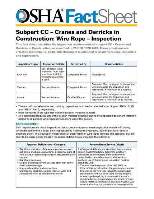
Strand laid rope is a wire rope made with strands (usually six or eight) wrapped around a fiber core, wire strand core, or independent wire rope core (IWRC).
Sling use. Employers must use only wire-rope slings that have permanently affixed and legible identification markings as prescribed by the manufacturer, and that indicate the recommended safe working load for the type(s) of hitch(es) used, the angle upon which it is based, and the number of legs if more than one.
Cable laid and 6 × 19 and 6 × 37 slings shall have a minimum clear length of wire rope 10 times the component rope diameter between splices, sleeves or end fittings.
Safe operating temperatures. Fiber core wire rope slings of all grades shall be permanently removed from service if they are exposed to temperatures in excess of 200 °F. When nonfiber core wire rope slings of any grade are used at temperatures above 400 °F or below minus 60 °F, recommendations of the sling manufacturer regarding use at that temperature shall be followed.
Sling use. Employers must use natural and synthetic fiber-rope slings that have permanently affixed and legible identification markings stating the rated capacity for the type(s) of hitch(es) used and the angle upon which it is based, type of fiber material, and the number of legs if more than one.
Safe operating temperatures. Natural and synthetic fiber rope slings, except for wet frozen slings, may be used in a temperature range from minus 20 °F to plus 180 °F without decreasing the working load limit. For operations outside this temperature range and for wet frozen slings, the sling manufacturer"s recommendations shall be followed.
Splicing. Spliced fiber rope slings shall not be used unless they have been spliced in accordance with the following minimum requirements and in accordance with any additional recommendations of the manufacturer:
In manila rope, eye splices shall consist of at least three full tucks, and short splices shall consist of at least six full tucks, three on each side of the splice center line.
In synthetic fiber rope, eye splices shall consist of at least four full tucks, and short splices shall consist of at least eight full tucks, four on each side of the center line.
Strand end tails shall not be trimmed flush with the surface of the rope immediately adjacent to the full tucks. This applies to all types of fiber rope and both eye and short splices. For fiber rope under one inch in diameter, the tail shall project at least six rope diameters beyond the last full tuck. For fiber rope one inch in diameter and larger, the tail shall project at least six inches beyond the last full tuck. Where a projecting tail interferes with the use of the sling, the tail shall be tapered and spliced into the body of the rope using at least two additional tucks (which will require a tail length of approximately six rope diameters beyond the last full tuck).
Removal from service. Natural and synthetic fiber rope slings shall be immediately removed from service if any of the following conditions are present:


 8613371530291