
wire rope ferrule installation free sample
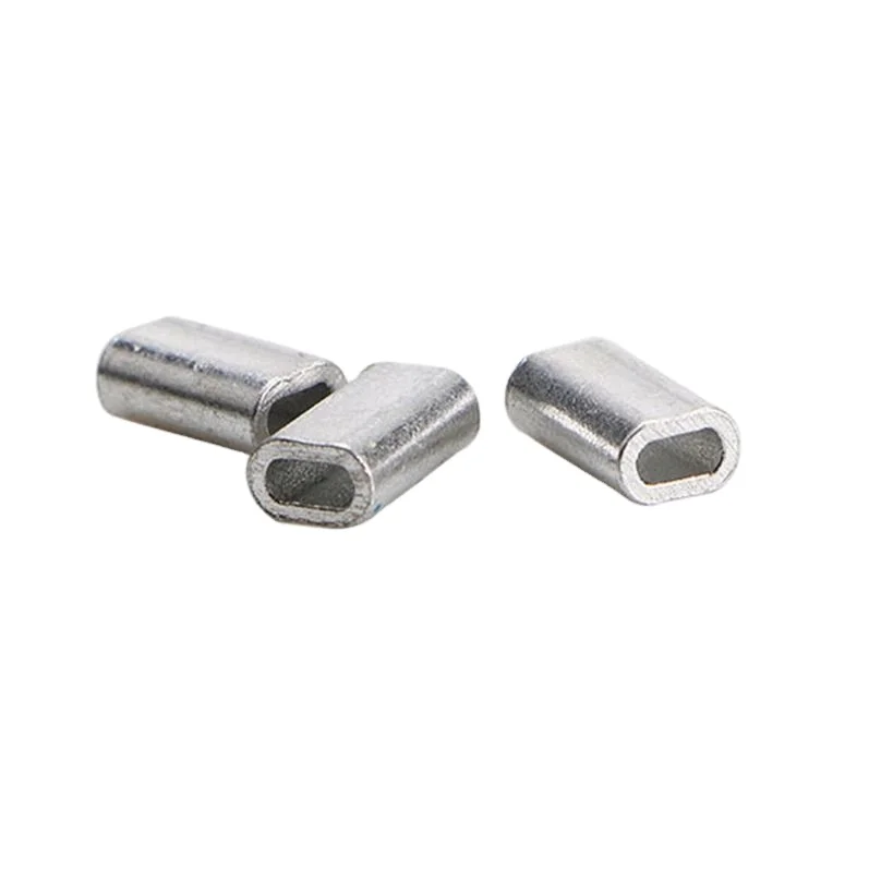
Our fishing wire single crimp sleeves are made of quality aluminum. No burrs, no sharp edges, corrosion resistant and with high strength, they are nicely crafted. Light, small and cute thing to connect mono and wire leader or other leader materials. Once connected to the line or wire, it ensure a firm hold.
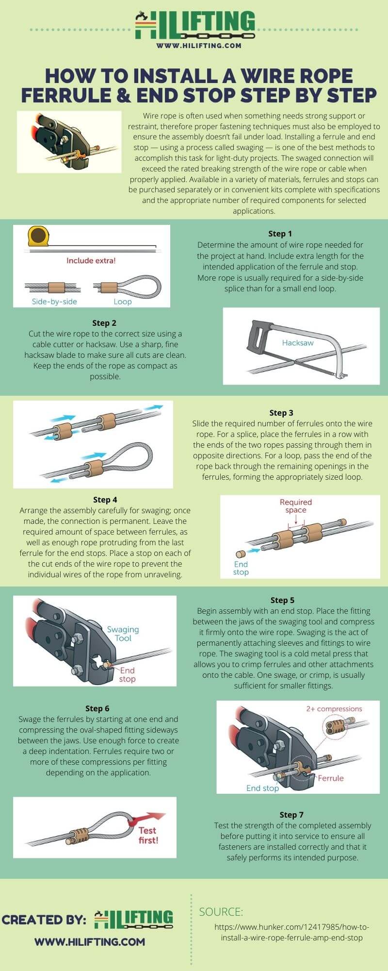
Determine the amount of wire rope needed for the project at hand. Include extra length for the intended application of the ferrule and stop. More rope is usually required for a side-by-side splice than for a small end loop.
Cut the wire rope to the correct size using a cable cutter or hacksaw. Use a sharp, fine hacksaw blade to make sure all cuts are clean. Keep the ends of the rope as compact as possible.
Slide the required number of ferrules onto the wire rope. For a splice, place the ferrules in a row with the ends of the two ropes passing through them in opposite directions. For a loop, pass the end of the rope back through the remaining openings in the ferrules, forming the appropriately sized loop.
Arrange the assembly carefully for swaging; once made, the connection is permanent. Leave the required amount of space between ferrules, as well as enough rope protruding from the last ferrule for the end stops. Place a stop on each of the cut ends of the wire rope to prevent the individual wires of the rope from unraveling.
Begin assembly with an end stop. Place the fitting between the jaws of the swaging tool and compress it firmly onto the wire rope. Swaging is the act of permanently attaching sleeves and fittings to wire rope. The swaging tool is a cold metal press that allows you to crimp ferrules and other attachments onto the cable. One swage, or crimp, is usually sufficient for smaller fittings.
Swage the ferrules by starting at one end and compressing the oval-shaped fitting sideways between the jaws. Use enough force to create a deep indentation. Ferrules require two or more of these compressions per fitting depending on the application.

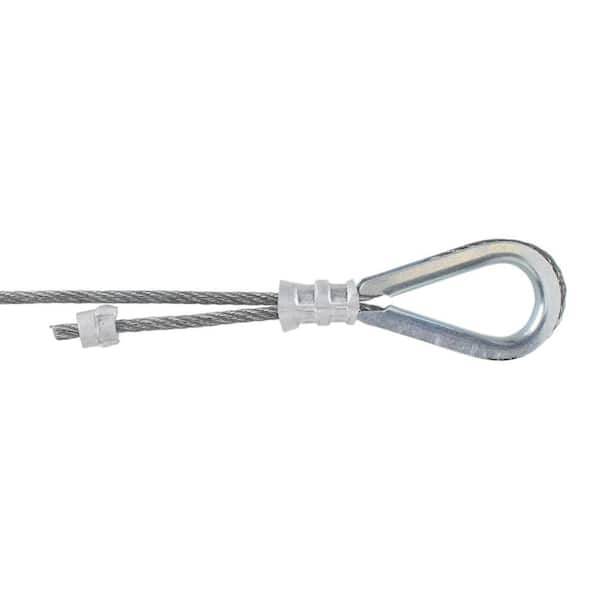
Wire rope thimbles also known as cable thimbles, are used for making reinforce loop(eyelet) with grips, clips or clamps by preventing fraying caused by friction at the bearing anchor point to protect and extend the service life of the wire rope or sling. They are just one of the many types of wire rope fittings (ferrules, wire rope clips, terminals, etc.).
Wire rope thimbles are available in a variety of strengths and materials(carbon steel and stainless steel, see our post on Surface Finish: 4 Common Types You Should Know) but mainly they come in two different duty grades.
If you use it in high moisture or corrosive environments, recommend our stainless steel wire rope thimbles which can offer resistance to corrosion on the surface, particularly in marine applications.
Simply wrap the end of the wire rope around the outer groove of the thimble, lace the dead end of the wire rope past the U-bolt of the wire rope grips or a wire rope ferrule crimp to hold onto the bearing anchor point at the end of the thimble to prevent fraying caused by friction.
Once in place, put another wire rope clip as near the loop you just wrapped over the thimble. Turn nuts firmly but do not yet tighten to the proper torque, we recommend using a crimping/swaging tool to compress the ferrule firmly onto the rope to hold your thimble loop securely.
Alternatively, you can use a wire rope ferrule crimp to secure your thimble in place. this method is quick and easy to install. For further information on installation using a wire rope ferrule please – click here
Wire rope thimbles are used in conjunction with cable and rope to protect the eyes and will allow for smooth rope guiding around natural curves. So that the most important thing is to make sure the thimble eye securely fastened. Here are some tips for correctly using wire rope thimble:
Make sure that the cable thimbles size properly and securely fastened in the eye of the loop, not too loose or too tighten, so they can create an extra layer of support to connect with other properly sized rigging fittings.
While you are using a vinyl coated cable, you should multiply the actual size of the cable, usually use a larger size thimble than normal, for the actual diameter is the thickness of the vinyl coating plus the inside wire rope diameter. For example, if you are using a 5/16″ vinyl coated cable that is coated to 3/8″ diameter, you’d want to use a 3/8″ wire rope thimble.
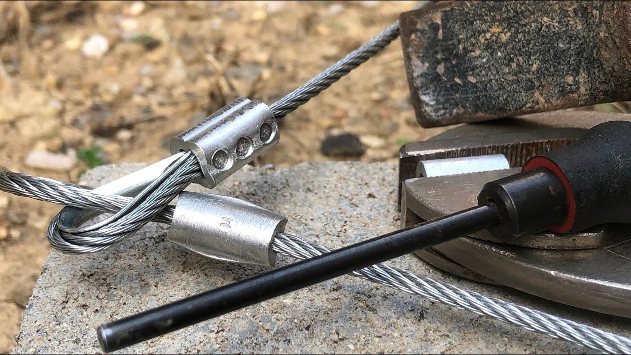
THIS METHOD SHOULD NEVER BE USED ON WIRE ROPE INTENDED FOR LIFTING PURPOSES. THE RESULT SHOULD BE ADEQUATELY TESTED WITH AN INTENDED LOAD UNDER CONTROLLED CONDITIONS WHILE HORIZONTAL BEFORE USING IT IN THE FIELD.
Using a nail about 3/16" dia. (for a 3/16" ID ferrule) laid across a DOUBLE ferrule, put 2 dents on one side, no closer than within 25% of the END of the ferrule flip it over and put the 3rd dent on the opposite side, spaced between the first 2.
I use a traditional anvil"s surface, but if you have a vice with an anvil surface behind the jaws, or a piece of railroad rail, or any THICK piece of scrap steel, lay the cable and ferrule on that.
DO NOT DO THIS ON BARE CONCRETE-its an eye hazard and you can easily damage the concrete surface. Plus the ferrule doesn"t look as good when you"re finished.
L. WERNS/NG United States Patent FERRULE FOR HOLDING END LOOPS IN WIRE ROPE Kenneth L. Wernsing, Portland, Oreg., assiguor to The Skookum Company, Inc., Portland, Oreg., a corporation of Oregon Application February 25, 1957, Serial No. 642,128 1 Claim. (Cl. 24-123) This invention relates to ferrules for holding end loops or eye splices in wire ropes and cables.
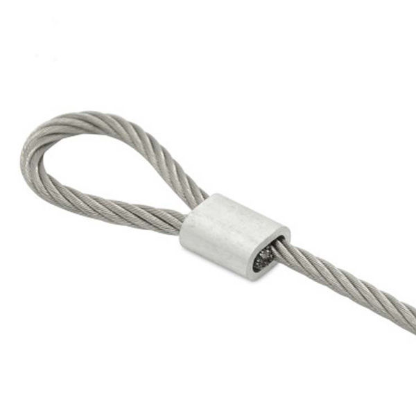
It is well known to form a loop in a wire rope by passing the end of the rope through a ferrule or sleeve, bending the section of the rope which has been passed through the ferrule into a loop, passing the end of the rope back through the ferrule in the opposite direction, and then swaging the ferrule upon the two courses of the rope.
It is the general object of the present invention to provide for use in the foregoing procedure an improved ferrule characterized by several significant advantages, i.e.:
Fourth, the free end of the cable is contained entirely within the ferrule so that dangerous, needle sharp strands do not extend outwardly therefrom, even though rope elongation occurs during swaging.
And Figs. 2 and 3 are sectional views in side elevation of the herein described ferrule with the wire rope inserted therein before and after swaging, respectively.
The ferrule of my invention comprises a tube indicated generally at of substantially elliptical cross section. The body 12 of this tube is dimensioned to receive two courses of wire rope or cable 14, lying side by side, parallel to each other. The rearward segment 16 of the tube is flared outwardly for easy insertion of the rope. The forward segment 18 is tapered in the indicated manner. It is provided with an offset opening 20 dimensioned to receive a single course only of the rope.
Accordingly it will be apparent that the wire rope or cable may be inserted through opening 20 and through the body 12 of the ferrule, passed out flared end 16 thereof, formed into a loop, and the free end inserted into the ferrule until it abuts against the closed portion of tapered nose section 18. The rope then may be adjusted until a loop of the desired size has been formed, as indicated in Fig. 2.
The ferrule then may be swaged by hammering it between dies of appropraite contour having a diameter corresponding approximately to the resultant diameter desired in the swaged ferrule. The swaging reduces the outer and inner dimensions of the ferrule, and changes the elliptical form to substantially cylindrical form. Also, it mashes the adjacent courses of the wire rope into each other and into the side walls of the ferrule so that the rope is confined securely in a loop or eye splice of the desired dimensions.
While the rope is being introduced into the ferrule, it is maintained straight at all times so that the free end may be inserted into the ferrule to maximum depth. This insures that a strong connection will be formed and prevents projection of sharp strands outside the ferrule. Accordingly, a safe, strong eye splice is produced.
A ferrule for holding end loops in wire rope comprising a deformable tube of substantially elliptical cross section, and a tapered projecting nose section of substantially elliptical cross section integral with the tube, the nose section having an opening through one side thereof offset from the longitudinal center of the ferrule, the tube being dimensioned to receive two parallel unbent courses of Wire rope, one course passing through said opening on one side of the tapered nose and the other course abutting against the inner surface of the other side thereof.
European foreword ................................................................................................................................................................ 4
5.1 Ferrule-secured system ......................................................................................................................................... 8
5.2 Ferrules ..................................................................................................................................................................... 10
5.3 Ferrule-securing .................................................................................................................................................... 11
5.3.2 Matching of ferrule to wire rope ...................................................................................................................... 11
5.3.4 Pressing the ferrule .............................................................................................................................................. 13
5.3.5 Quality control after pressing of the ferrule ............................................................................................... 14
A.3 Ropes for this design of ferrule ........................................................................................................................ 17
A.3.2 Rope types ................................................................................................................................................................ 17
A.3.4 Rope grade ............................................................................................................................................................... 17
A.3.5 Types of rope lay .................................................................................................................................................... 17
A.6 Matching wire rope to ferrule ........................................................................................................................... 21
A.7.1 Positioning of ferrule (Types A and B) ........................................................................................................... 24
A.7.2 Pressing the ferrule .............................................................................................................................................. 25
A.7.3 Ferrules after pressing ........................................................................................................................................ 25

Wire rope and cable are each considered a “machine”. The configuration and method of manufacture combined with the proper selection of material when designed for a specific purpose enables a wire rope or cable to transmit forces, motion and energy in some predetermined manner and to some desired end.
Two or more wires concentrically laid around a center wire is called a strand. It may consist of one or more layers. Typically, the number of wires in a strand is 7, 19 or 37. A group of strands laid around a core would be called a cable or wire rope. In terms of product designation, 7 strands with 19 wires in each strand would be a 7×19 cable: 7 strands with 7 wires in each strand would be a 7×7 cable.
Materials Different applications for wire rope present varying demands for strength, abrasion and corrosion resistance. In order to meet these requirements, wire rope is produced in a number of different materials.
Stainless Steel This is used where corrosion is a prime factor and the cost increase warrants its use. The 18% chromium, 8% nickel alloy known as type 302 is the most common grade accepted due to both corrosion resistance and high strength. Other types frequently used in wire rope are 304, 305, 316 and 321, each having its specific advantage over the other. Type 305 is used where non-magnetic properties are required, however, there is a slight loss of strength.
Galvanized Carbon Steel This is used where strength is a prime factor and corrosion resistance is not great enough to require the use of stainless steel. The lower cost is usually a consideration in the selection of galvanized carbon steel. Wires used in these wire ropes are individually coated with a layer of zinc which offers a good measure of protection from corrosive elements.
Cable Construction The greater the number of wires in a strand or cable of a given diameter, the more flexibility it has. A 1×7 or a 1×19 strand, having 7 and 19 wires respectively, is used principally as a fixed member, as a straight linkage, or where flexing is minimal.
Selecting Wire Rope When selecting a wire rope to give the best service, there are four requirements which should be given consideration. A proper choice is made by correctly estimating the relative importance of these requirements and selecting a rope which has the qualities best suited to withstand the effects of continued use. The rope should possess:Strength sufficient to take care of the maximum load that may be applied, with a proper safety factor.
Strength Wire rope in service is subjected to several kinds of stresses. The stresses most frequently encountered are direct tension, stress due to acceleration, stress due to sudden or shock loads, stress due to bending, and stress resulting from several forces acting at one time. For the most part, these stresses can be converted into terms of simple tension, and a rope of approximately the correct strength can be chosen. As the strength of a wire rope is determined by its, size, grade and construction, these three factors should be considered.
Safety Factors The safety factor is the ratio of the strength of the rope to the working load. A wire rope with a strength of 10,000 pounds and a total working load of 2,000 pounds would be operating with a safety factor of five.
It is not possible to set safety factors for the various types of wire rope using equipment, as this factor can vary with conditions on individual units of equipment.
The proper safety factor depends not only on the loads applied, but also on the speed of operation, shock load applied, the type of fittings used for securing the rope ends, the acceleration and deceleration, the length of rope, the number, size and location of sheaves and drums, the factors causing abrasion and corrosion and the facilities for inspection.
Fatigue Fatigue failure of the wires in a wire rope is the result of the propagation of small cracks under repeated applications of bending loads. It occurs when ropes operate over comparatively small sheaves or drums. The repeated bending of the individual wires, as the rope bends when passing over the sheaves or drums, and the straightening of the individual wires, as the rope leaves the sheaves or drums, causing fatigue. The effect of fatigue on wires is illustrated by bending a wire repeatedly back and forth until it breaks.
The best means of preventing early fatigue of wire ropes is to use sheaves and drums of adequate size. To increase the resistance to fatigue, a rope of more flexible construction should be used, as increased flexibility is secured through the use of smaller wires.
Abrasive Wear The ability of a wire rope to withstand abrasion is determined by the size, the carbon and manganese content, the heat treatment of the outer wires and the construction of the rope. The larger outer wires of the less flexible constructions are better able to withstand abrasion than the finer outer wires of the more flexible ropes. The higher carbon and manganese content and the heat treatment used in producing wire for the stronger ropes, make the higher grade ropes better able to withstand abrasive wear than the lower grade ropes.
Effects of Bending All wire ropes, except stationary ropes used as guys or supports, are subjected to bending around sheaves or drums. The service obtained from wire ropes is, to a large extent, dependent upon the proper choice and location of the sheaves and drums about which it operates.
A wire rope may be considered a machine in which the individual elements (wires and strands) slide upon each other when the rope is bent. Therefore, as a prerequisite to the satisfactory operation of wire rope over sheaves and drums, the rope must be properly lubricated.
Loss of strength due to bending is caused by the inability of the individual strands and wires to adjust themselves to their changed position when the rope is bent. Tests made by the National Institute of Standards and Technology show that the rope strength decreases in a marked degree as the sheave diameter grows smaller with respect to the diameter of the rope. The loss of strength due to bending wire ropes over the sheaves found in common use will not exceed 6% and will usually be about 4%.
The bending of a wire rope is accompanied by readjustment in the positions of the strands and wires and results in actual bending of the wires. Repetitive flexing of the wires develops bending loads which, even though well within the elastic limit of the wires, set up points of stress concentration.
The fatigue effect of bending appears in the form of small cracks in the wires at these over-stressed foci. These cracks propagate under repeated stress cycles, until the remaining sound metal is inadequate to withstand the bending load. This results in broken wires showing no apparent contraction of cross section.
Experience has established the fact that from the service view-point, a very definite relationship exists between the size of the individual outer wires of a wire rope and the size of the sheave or drum about which it operates. Sheaves and drums smaller than 200 times the diameter of the outer wires will cause permanent set in a heavily loaded rope. Good practice requires the use of sheaves and drums with diameters 800 times the diameter of the outer wires in the rope for heavily loaded fast-moving ropes.
It is impossible to give a definite minimum size of sheave or drum about which a wire rope will operate with satisfactory results, because of the other factors affecting the useful life of the rope. If the loads are light or the speed slow, smaller sheaves and drums can be used without causing early fatigue of the wires than if the loads are heavy or the speed is fast. Reverse bends, where a rope is bent in one direction and then in the opposite direction, cause excessive fatigue and should be avoided whenever possible. When a reverse bend is necessary larger sheaves are required than would be the case if the rope were bent in one direction only.
Stretch of Wire Rope The stretch of a wire rope under load is the result of two components: the structural stretch and the elastic stretch. Structural stretch of wire rope is caused by the lengthening of the rope lay, compression of the core and adjustment of the wires and strands to the load placed upon the wire rope. The elastic stretch is caused by elongation of the wires.
The structural stretch varies with the size of core, the lengths of lays and the construction of the rope. This stretch also varies with the loads imposed and the amount of bending to which the rope is subjected. For estimating this stretch the value of one-half percent, or .005 times the length of the rope under load, gives an approximate figure. If loads are light, one-quarter percent or .0025 times the rope length may be used. With heavy loads, this stretch may approach one percent, or .01 times the rope length.
The elastic stretch of a wire rope is directly proportional to the load and the length of rope under load, and inversely proportional to the metallic area and modulus of elasticity. This applies only to loads that do not exceed the elastic limit of a wire rope. The elastic limit of stainless steel wire rope is approximately 60% of its breaking strength and for galvanized ropes it is approximately 50%.
Preformed Wire Ropes Preformed ropes differ from the standard, or non-preformed ropes, in that the individual wires in the strands and the strands in the rope are preformed, or pre-shaped to their proper shape before they are assembled in the finished rope.
This, in turn, results in preformed wire ropes having the following characteristics:They can be cut without the seizings necessary to retain the rope structure of non-preformed ropes.
They are substantially free from liveliness and twisting tendencies. This makes installation and handling easier, and lessens the likelihood of damage to the rope from kinking or fouling. Preforming permits the more general use of Lang lay and wire core constructions.
Removal of internal stresses increase resistance to fatigue from bending. This results in increased service where ability to withstand bending is the important requirement. It also permits the use of ropes with larger outer wires, when increased wear resistance is desired.
Outer wires will wear thinner before breaking, and broken wire ends will not protrude from the rope to injure worker’s hands, to nick and distort adjacent wires, or to wear sheaves and drums. Because of the fact that broken wire ends do not porcupine, they are not as noticeable as they are in non-preformed ropes. This necessitates the use of greater care when inspecting worn preformed ropes, to determine their true condition.

Wire rope is an extremely versatile mechanical device that can be used to help support and move an object or load. Whether for use on cranes or for other lifting applications, it’s important to have a solid understanding of the rigging components that are being used to attach to and lift a load.
As a rigger or end-user of wire rope, it’s necessary to understand the types of wire rope end termination, or treatments that can be used at the ends of a length of wire rope—one of the most common being wire rope clips.
Wire rope clips can be used to form a load bearing eye at the end of a cable or wire rope, or to connect two cables together with a lap splice. Wire rope clips are popular because they can be installed in the field and provide 80-90% efficiency of the rope breaking strength, depending on the diameter of the wire rope.
As a general guideline, they are NOT to be used for making slings, as ASME B30.9 Slingsstandard states: “Mechanical wire rope terminations requiring periodic adjustment to maintain efficiency shall not be used to fabricate slings.”
There are two main types of wire rope clips—U-Bolt and double saddle clips. U-Bolt wire rope clips are the most common and may be made of forged or malleable metal.
This type of wire rope clip is essentially a U-bolt, two nuts, and a metal base (saddle) that can be made from forged steel or cast iron. Careful consideration and attention must be given to the way U-bolt type wire rope clips are installed.
The base of the wire rope clip is made from forged steel. Forged clips are heated and hammered into the desired shape—resulting in a consistent grain structure in the steel. Forged wire rope clips are used for critical, heavy-duty, overhead loads such as winch lines, crane hoist lines, support lines, guy lines, towing lines, tie downs, scaffolds, etc.
Malleable wire rope clips are used for making eye termination assemblies only with right regular lay wire rope and only for light duty uses with small applied loads, such as hand rails, fencing, guard rails, etc. The base of the wire rope clips is made from malleable cast iron, which may fracture under heavy use and does not have the desirable metal properties of steel, or the beneficial grain structure that a forged base has.
Unfortunately, it is not uncommon to see a wire rope clip applied incorrectly. Some of the most common mistakes include:Not torquing to the manufacturer’s expectations
Wire rope clips require the use of a torque wrench in order to function properly. Torquing the nuts on the clips too much or too little can cause the clip to fail. If the clip is over-torqued, it could damage the threads of the wire rope. If the clip is under-torqued, the holding power of the clip is diminished and the wire rope could slip through.
There are a minimum number of clips required for use related to the wire rope diameter. Using less than the number of specified clips could result in decreased efficiency and possible failure.
Depending on the number and size of the wire rope clips, there is a proportional amount of space required between the placement on each clip on the rope.
There are two sides of a U-Bolt style wire rope clip: the saddle and the U-Bolt. When securing a wire rope eye, it is important to place the clip on the correct end of the rope.
A saying commonly used in rigging to help remember this is: “Never saddle a dead horse!” In other words, never put the saddle on the dead end of the rope.
The turnback is the portion of the wire rope eye that runs from the end of the bearing eye to the live end. Having less than the suggested amount of turnback will decrease the efficiency of the wire rope eye and could lead to failure.
It is important to be sure you are using the correct wire rope clip—forged or malleable wire rope clips—for the application. Malleable clips can only be used for non-critical uses, such as tension rope to form a perimeter around a parking lot.
If the use is critical—an application where, if there is a failure, you have potential injury or loss of life or damage to property—a forged clip must be used.
The clip size used—whether it be 1/8”, 3”, or otherwise—must match the diameter size of the wire rope. If it doesn’t, the wire rope could slip out of the clip.
After installing clips, it is necessary to regularly cycle the rope and retighten the clips. Monitoring the torque on the nuts is important, as they will loosen over repeated use.
Basic steps for installing a wire rope clip include:First, wrap the wire rope around the thimble or to form the eye, and turn back the correct amount of rope—as specified by the manufacturer.
Apply the first wire rope clip at the end of the dead end, with one base width of space. Use a torque wrench to tighten the nuts on the wire rope clip.
When applying the second clip (if required), place it as close to the eye loop or thimble as possible. Again, be sure to properly tighten the nuts of the clip with a torque wrench.
Wire rope clips are a common and necessary piece of rigging hardware when it comes to using wire rope and forming end terminations. They are used to form a wire rope eye or to connect two cables together. It’s important to understand how to correctly install a wire rope clip, as incorrect installation leads to decreased efficiency in the wire rope assembly.


 8613371530291