
wire rope inspection pdf quotation
In the rigging businesses, there are ample protocols and procedures for cable rigging hardware that are designed to ensure safety. One protocol that is crucial to follow is the inspection of wire ropes. Below, we have provided information on who should inspect the wire ropes, how to inspect them, and when to stop using them. Continue reading for our wire rope inspection checklist.
To ensure the wire ropes are safe, you shouldn’t let just anybody conduct the inspections. Riggers train professionally and have to keep up to date with their knowledge and expertise. Therefore, those professionals and experts are the only ones who should conduct the inspections. Keep in mind that an individual who uses the wire rope frequently should not be the one to also inspect the wire rope. Getting a new set of eyes on the wire rope will ensure nothing is overlooked.
Not only should you inspect the wire ropes every day at the start of each shift, but you should also inspect them before every use. It is crucial that you note and document this inspection and keep track of the records pertaining to the condition of the wire rope. Communication is crucial in this regard.
Rag-and-Visual: This allows you to look for external damage to the wire rope. All you must do is grab the rope lightly and move a cotton cloth or rag slowly down the wire. If the rag snags on any part of the wire, inspect that area to see how extreme the broken wire is.
Visually Assess: Just taking the time to look over the entire wire rope will help you catch breaks and other problems that you might not have noticed with the rag. These might be abrasions, corrosions, and lubrication inside the rope.
Measure Rope Diameter: Once you measure the rope’s current diameter, compare it to the rope’s original diameter. If the measures are not the same, there is likely a problem. The issue is most likely an internal or external rope issue.
Make sure to complete each of these steps thoroughly to ensure the safety and security of the individuals using the ropes. Not completing a step or overlooking an area can be extremely dangerous and harmful.
If you complete an inspection and find that a rope does not meet expectations, you should not use that rope until it has been repaired or replaced. Whether you can tell that the rope has heat damage, has been stretched and overused, or has been kinked or crushed, you should stop using it immediately. If you are unsure whether an issue is large enough to stop using the item, ask someone. Don’t just assume it is safe!

A competent person must begin a visual inspection prior to each shift the equipment is used, which must be completed before or during that shift. The inspection must consist of observation of wire ropes (running and standing) that are likely to be in use during the shift for apparent deficiencies, including those listed in paragraph (a)(2) of this section. Untwisting (opening) of wire rope or booming down is not required as part of this inspection.
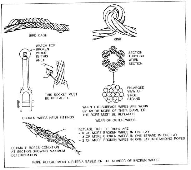
Significant distortion of the wire rope structure such as kinking, crushing, unstranding, birdcaging, signs of core failure or steel core protrusion between the outer strands.
In running wire ropes: Six randomly distributed broken wires in one rope lay or three broken wires in one strand in one rope lay, where a rope lay is the length along the rope in which one strand makes a complete revolution around the rope.
In rotation resistant ropes: Two randomly distributed broken wires in six rope diameters or four randomly distributed broken wires in 30 rope diameters.
In pendants or standing wire ropes: More than two broken wires in one rope lay located in rope beyond end connections and/or more than one broken wire in a rope lay located at an end connection.
If a deficiency in Category I (see paragraph (a)(2)(i) of this section) is identified, an immediate determination must be made by the competent person as to whether the deficiency constitutes a safety hazard. If the deficiency is determined to constitute a safety hazard, operations involving use of the wire rope in question must be prohibited until:
If the deficiency is localized, the problem is corrected by severing the wire rope in two; the undamaged portion may continue to be used. Joining lengths of wire rope by splicing is prohibited. If a rope is shortened under this paragraph, the employer must ensure that the drum will still have two wraps of wire when the load and/or boom is in its lowest position.
If a deficiency in Category II (see paragraph (a)(2)(ii) of this section) is identified, operations involving use of the wire rope in question must be prohibited until:
The employer complies with the wire rope manufacturer"s established criterion for removal from service or a different criterion that the wire rope manufacturer has approved in writing for that specific wire rope (see § 1926.1417),
If the deficiency is localized, the problem is corrected by severing the wire rope in two; the undamaged portion may continue to be used. Joining lengths of wire rope by splicing is prohibited. If a rope is shortened under this paragraph, the employer must ensure that the drum will still have two wraps of wire when the load and/or boom is in its lowest position.
If the deficiency (other than power line contact) is localized, the problem is corrected by severing the wire rope in two; the undamaged portion may continue to be used. Joining lengths of wire rope by splicing is prohibited. Repair of wire rope that contacted an energized power line is also prohibited. If a rope is shortened under this paragraph, the employer must ensure that the drum will still have two wraps of wire when the load and/or boom is in its lowest position.
Where a wire rope is required to be removed from service under this section, either the equipment (as a whole) or the hoist with that wire rope must be tagged-out, in accordance with § 1926.1417(f)(1), until the wire rope is repaired or replaced.
The inspection must include any deficiencies that the qualified person who conducts the annual inspection determines under paragraph (c)(3)(ii) of this section must be monitored.
Wire ropes on equipment must not be used until an inspection under this paragraph demonstrates that no corrective action under paragraph (a)(4) of this section is required.
At least every 12 months, wire ropes in use on equipment must be inspected by a qualified person in accordance with paragraph (a) of this section (shift inspection).
The inspection must be complete and thorough, covering the surface of the entire length of the wire ropes, with particular attention given to all of the following:
Exception: In the event an inspection under paragraph (c)(2) of this section is not feasible due to existing set-up and configuration of the equipment (such as where an assist crane is needed) or due to site conditions (such as a dense urban setting), such inspections must be conducted as soon as it becomes feasible, but no longer than an additional 6 months for running ropes and, for standing ropes, at the time of disassembly.
If the deficiency is localized, the problem is corrected by severing the wire rope in two; the undamaged portion may continue to be used. Joining lengths of wire rope by splicing is prohibited. If a rope is shortened under this paragraph, the employer must ensure that the drum will still have two wraps of wire when the load and/or boom is in its lowest position.
If the qualified person determines that, though not presently a safety hazard, the deficiency needs to be monitored, the employer must ensure that the deficiency is checked in the monthly inspections.
All documents produced under this section must be available, during the applicable document retention period, to all persons who conduct inspections under this section.

Large number of ferrous steel wire ropes is in use in different industries, carrying people and freight, supporting bridges and towers, lifting pipes and vessels offshore and onshore, underground and aboveground. The bigger and the longer is the rope, the more expensive it is. Later or sooner ropes deteriorate for different reasons, their further use may be dangerous, and important question arise: whether the rope should be discarded or still may remain in operation. Premature discard and…Expand
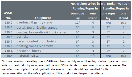
Wire ropes undergo constant stress and wear through daily use. So, wire rope requires monthly inspection in accordance with this section to reduce the risk of failure and potential resulting injury or property damage. In addition, this section covers criteria to use in determining when to replace rope, and requires inspection of rope on equipment that has been idle for a month or more, before the rope and equipment can be returned to service.
A thorough inspection of all ropes shall be made at least once a month and a certification record which included the date of inspection, the signature of the person who performed the inspection and an identifier for the ropes which were inspected shall be kept on file where readily available to appointed personnel. Any deterioration, resulting in appreciable loss of original strength, shall be carefully observed and determination made as to whether further use of the rope would constitute a safety hazard. Some of the conditions that could result in an appreciable loss of strength are the following:
All rope which has been idle for a period of a month or more due to shutdown or storage of a crane on which it is installed shall be given a thorough inspection before it is used. This inspection shall be for all types of deterioration and shall be performed by an appointed person whose approval shall be required for further use of the rope. A certification record shall be available for inspection which includes the date of inspection, the signature of the person who performed the inspection and an identifier for the rope which was inspected.
Wear and damage to wire rope can’t always be seen on the surface. Konecranes RopeQ Magnetic Rope Inspection pairs visual inspection with non-destructive testing to detect internal broken wires that may escape detection through traditional inspection methods.
Wire rope slings have played a critical role in applications like lifting, rigging, and hoisting. They are usually made from galvanized or un-galvanized steel wire strands, which are woven into ropes with end terminations. The end terminations can be loops or hooks.
Several industries, such as mining, manufacturing, shipping, and power generation, use wire rope slings because they are easy-to-use, cost effective, and reliable. Depending on the type of load and crane, you can use an assembly of wire rope slings for lifting, rigging, and hoisting.
Although they are extremely strong and durable, wire rope slings require regular maintenance and inspection. They must be inspected to ensure safety and prevent economic losses. In this short guide, we will take a look at wire rope sling inspection, maintenance, and replacement.
As mentioned before, the purpose of wire rope sling inspection is to identify any damage or excessive wear before it leads to a disaster. Two leading organizations in the US, OSHA, and ASME have published inspection and maintenance guidelines to ensure wire rope slings safety and functionality.
The two standards governing the criteria and guidelines of wire rope sling inspection are OSHA 1910.184 and ASME B30.9. As per these guidelines, there are three types of inspections.
This inspection should be carried out immediately after receiving the wire rope slings. During this inspection, make sure to check the sling identification tags. These tags will bear the product information, its rated load capacity, and other specifications. Check if they are what you ordered and what you need.
The second type of wire rope sling inspection is to be carried out daily or prior to use. As wire rope slings are used in a wide range of applications, it is always better to inspect them before each use. In other words, if you are going to use a sling three times a day, you should inspect it three times.
As wire rope slings can get damaged during a loading or rigging application, this inspection is extremely critical. You can have designated personnel, usually a competent crew member, to inspect wire rope slings before each use.
Only a certified professional or service provider can carry out periodic inspections. You also need to document each periodic inspection and maintain records, as per the ASME B30.9 guidelines. The schedule of periodic wire rope sling inspection depends on factors like frequency of use, the severity of work conditions, type of lifting or rigging, and experience gained on the service life of wire rope slings used in similar applications.
Even though it’s usually a visual inspection, you have to be thorough with it. Neither OSHA nor ASME has specified any fixed sling inspection process. You need to set up a process of your own based on your requirements, rope sling usage, and other factors.
Usually, a proper wire rope sling inspection process should include the following steps:Make sure to lay down the sling on a flat surface in such a way that all its areas are visible and easily accessible.
If possible, maintain a detailed record of all your sling inspections. Well-kept records make it easier to identify slings that are nearing the end of their service life or are damaged.
Sling tag identification is the most critical step in sling inspection. These tags help you identify the usage specifications of the slings. So, make sure to maintain the tags in excellent condition throughout the lifespan of the slings. If the tag is damaged or illegible, remove the sling from use immediately.
If you come across any of the following scenarios during your sling inspection, you will need to remove the slings immediately. Furthermore, if you are unsure of the potential damage, discontinue the use of slings.
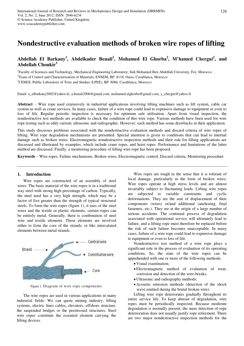
While the structure and specifications of wires vary greatly, wire rope slings often have the following four key components:Core: The core is made from steel, synthetic, or natural fibers. The function of the core is to provide strength and support to the wires.
Wires: Wires are made from materials like steel, iron, bronze, and stainless steel. Wires surround the core, and they come in different sizes and strengths.
The guidelines for allowable broken wires are as follows:Single Part Body Slings and Strand Laid Grommets:5 broken wires in one strand in one rope lay
Distortion constitutes damages like kinking, crushing, and birdcaging, among others. If you see any such damage or wires and strands pushed out of their original positions, you need to replace the wire rope sling immediately.
Wire rope damage due to heat results in metallic discoloration, fusing of wires, or loss of lubricant. Make sure to replace the sling if there is heat damage.
While light surface rust will not affect the strength of wire rope slings, you will need a replacement if the corrosion has caused pitting or binding of wires.
When using wire rope slings, pulling through a loop can push out wires and strands from their original positions, pushing the slings out of balance. If you see this damage, replace the slings immediately.
Kinks are nothing but loops with permanent wire and strand distortions. As this type of damage is irreparable, you need to replace the slings right away.
Improper use of wire rope slings can cause doglegs, which are permanent bends. If the slings have minor doglegs with no strand distortion or if you can’t see them when the sling is under tension, you can continue using the sling. However, replacement is necessary if the doglegs are severe.
Make sure to discard the damaged wire rope slings in an eco-friendly manner. You should label the slings “Do Not Use” to avoid accidental use. Then, you should cut the eye and fittings from the rope, cut the rope into 3’ to 4’ sections, and send them for recycling.
The third most important step is wire rope sling maintenance. You should keep the following points in mind to ensure regular and comprehensive maintenance:Always keep the slings off the ground, in hanging position, and in a dry and cool environment.
Wire rope slings play a critical role in a wide range of industries such as mining, manufacturing, and shipping, among others. Although they are strong and have a long lifespan, rope slings do need regular inspection and maintenance to ensure safety and longevity. Hopefully, this guide will help clear all your doubts regarding wire rope sling inspection, replacement, and maintenance. If you need help with any rigging equipment inspection, maintenance, and replacement, feel free to reach out to our team at Holloway Houston Inc.

Wire Rope Inspection Services in the oil and gas industry with the use ofLRM®XXI Diagnostic System allows to get information about the technical condition of wire rope in full cross section and in full available length of wire rope in the fastest way.
With regular periodic wire rope inspection combined with data utilization of crane the it is possible to estimate the remaining lifetime of crane wires.
Due to cooperation with Laboratory LRM-NDE with success offshore companies has implemented inspections of cranes wire ropes with the use of LRM®XXI Diagnostic System according to MRT Examination procedure and international standards for offshore fleet.
Long-term cooperation with offshore companies has allowed Laboratory LRM-NDE to achieve the knowledge and necessary competence to design wire rope diagnostic system equipment that can meet the harsh environmental conditions at sea.

Applus+ Velosi uses next generation Electromagnetic wire rope inspection technology EMAG to identify the internal condition of wire ropes. Our equipment can measure loss of metallic cross-sectional area (LMA) caused by external and internal corrosion, wear, broken wires, broken cores and deformations in steel wire ropes. The software used can also analyze the wire rope roughness (WRR) to produce a quantitative characterization of the internal broken wire clusters and corrosion pitting. We can also produce a conventional localized flaw (LF) signal that can help to detect broken wires and corrosion pitting. EMAG can offer cost efficiencies by reducing the need for periodic wire rope replacement, as well as eliminating an annual slip and cut policy.
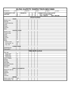
Guidelines for inspecting a wire rope system or installation are available in this brochure. The publication provides a clear and concise approach to assisting wire rope users" needs to comply with industry and governmental regulations that require inspections of individual ropes, fittings and attachments, as well as entire operating systems at regularly scheduled intervals. In addition to information and criteria, the brochure includes a blank Inspection Form, which may be copied for recording

In stricter senses, the term wire rope refers to a diameter larger than 9.5 mm (3⁄8 in), with smaller gauges designated cable or cords.wrought iron wires were used, but today steel is the main material used for wire ropes.
Historically, wire rope evolved from wrought iron chains, which had a record of mechanical failure. While flaws in chain links or solid steel bars can lead to catastrophic failure, flaws in the wires making up a steel cable are less critical as the other wires easily take up the load. While friction between the individual wires and strands causes wear over the life of the rope, it also helps to compensate for minor failures in the short run.
Wire ropes were developed starting with mining hoist applications in the 1830s. Wire ropes are used dynamically for lifting and hoisting in cranes and elevators, and for transmission of mechanical power. Wire rope is also used to transmit force in mechanisms, such as a Bowden cable or the control surfaces of an airplane connected to levers and pedals in the cockpit. Only aircraft cables have WSC (wire strand core). Also, aircraft cables are available in smaller diameters than wire rope. For example, aircraft cables are available in 1.2 mm (3⁄64 in) diameter while most wire ropes begin at a 6.4 mm (1⁄4 in) diameter.suspension bridges or as guy wires to support towers. An aerial tramway relies on wire rope to support and move cargo overhead.
Modern wire rope was invented by the German mining engineer Wilhelm Albert in the years between 1831 and 1834 for use in mining in the Harz Mountains in Clausthal, Lower Saxony, Germany.chains, such as had been used before.
Wilhelm Albert"s first ropes consisted of three strands consisting of four wires each. In 1840, Scotsman Robert Stirling Newall improved the process further.John A. Roebling, starting in 1841suspension bridge building. Roebling introduced a number of innovations in the design, materials and manufacture of wire rope. Ever with an ear to technology developments in mining and railroading, Josiah White and Erskine Hazard, principal ownersLehigh Coal & Navigation Company (LC&N Co.) — as they had with the first blast furnaces in the Lehigh Valley — built a Wire Rope factory in Mauch Chunk,Pennsylvania in 1848, which provided lift cables for the Ashley Planes project, then the back track planes of the Summit Hill & Mauch Chunk Railroad, improving its attractiveness as a premier tourism destination, and vastly improving the throughput of the coal capacity since return of cars dropped from nearly four hours to less than 20 minutes. The decades were witness to a burgeoning increase in deep shaft mining in both Europe and North America as surface mineral deposits were exhausted and miners had to chase layers along inclined layers. The era was early in railroad development and steam engines lacked sufficient tractive effort to climb steep slopes, so incline plane railways were common. This pushed development of cable hoists rapidly in the United States as surface deposits in the Anthracite Coal Region north and south dove deeper every year, and even the rich deposits in the Panther Creek Valley required LC&N Co. to drive their first shafts into lower slopes beginning Lansford and its Schuylkill County twin-town Coaldale.
The German engineering firm of Adolf Bleichert & Co. was founded in 1874 and began to build bicable aerial tramways for mining in the Ruhr Valley. With important patents, and dozens of working systems in Europe, Bleichert dominated the global industry, later licensing its designs and manufacturing techniques to Trenton Iron Works, New Jersey, USA which built systems across America. Adolf Bleichert & Co. went on to build hundreds of aerial tramways around the world: from Alaska to Argentina, Australia and Spitsbergen. The Bleichert company also built hundreds of aerial tramways for both the Imperial German Army and the Wehrmacht.
In the last half of the 19th century, wire rope systems were used as a means of transmitting mechanical powercable cars. Wire rope systems cost one-tenth as much and had lower friction losses than line shafts. Because of these advantages, wire rope systems were used to transmit power for a distance of a few miles or kilometers.
Steel wires for wire ropes are normally made of non-alloy carbon steel with a carbon content of 0.4 to 0.95%. The very high strength of the rope wires enables wire ropes to support large tensile forces and to run over sheaves with relatively small diameters.
In the mostly used parallel lay strands, the lay length of all the wire layers is equal and the wires of any two superimposed layers are parallel, resulting in linear contact. The wire of the outer layer is supported by two wires of the inner layer. These wires are neighbors along the whole length of the strand. Parallel lay strands are made in one operation. The endurance of wire ropes with this kind of strand is always much greater than of those (seldom used) with cross lay strands. Parallel lay strands with two wire layers have the construction Filler, Seale or Warrington.
In principle, spiral ropes are round strands as they have an assembly of layers of wires laid helically over a centre with at least one layer of wires being laid in the opposite direction to that of the outer layer. Spiral ropes can be dimensioned in such a way that they are non-rotating which means that under tension the rope torque is nearly zero. The open spiral rope consists only of round wires. The half-locked coil rope and the full-locked coil rope always have a centre made of round wires. The locked coil ropes have one or more outer layers of profile wires. They have the advantage that their construction prevents the penetration of dirt and water to a greater extent and it also protects them from loss of lubricant. In addition, they have one further very important advantage as the ends of a broken outer wire cannot leave the rope if it has the proper dimensions.
Stranded ropes are an assembly of several strands laid helically in one or more layers around a core. This core can be one of three types. The first is a fiber core, made up of synthetic material or natural fibers like sisal. Synthetic fibers are stronger and more uniform but cannot absorb much lubricant. Natural fibers can absorb up to 15% of their weight in lubricant and so protect the inner wires much better from corrosion than synthetic fibers do. Fiber cores are the most flexible and elastic, but have the downside of getting crushed easily. The second type, wire strand core, is made up of one additional strand of wire, and is typically used for suspension. The third type is independent wire rope core (IWRC), which is the most durable in all types of environments.ordinary lay rope if the lay direction of the wires in the outer strands is in the opposite direction to the lay of the outer strands themselves. If both the wires in the outer strands and the outer strands themselves have the same lay direction, the rope is called a lang lay rope (from Dutch langslag contrary to kruisslag,Regular lay means the individual wires were wrapped around the centers in one direction and the strands were wrapped around the core in the opposite direction.
Multi-strand ropes are all more or less resistant to rotation and have at least two layers of strands laid helically around a centre. The direction of the outer strands is opposite to that of the underlying strand layers. Ropes with three strand layers can be nearly non-rotating. Ropes with two strand layers are mostly only low-rotating.
Stationary ropes, stay ropes (spiral ropes, mostly full-locked) have to carry tensile forces and are therefore mainly loaded by static and fluctuating tensile stresses. Ropes used for suspension are often called cables.
Track ropes (full locked ropes) have to act as rails for the rollers of cabins or other loads in aerial ropeways and cable cranes. In contrast to running ropes, track ropes do not take on the curvature of the rollers. Under the roller force, a so-called free bending radius of the rope occurs. This radius increases (and the bending stresses decrease) with the tensile force and decreases with the roller force.
Wire rope slings (stranded ropes) are used to harness various kinds of goods. These slings are stressed by the tensile forces but first of all by bending stresses when bent over the more or less sharp edges of the goods.
Technical regulations apply to the design of rope drives for cranes, elevators, rope ways and mining installations. Factors that are considered in design include:
Donandt force (yielding tensile force for a given bending diameter ratio D/d) - strict limit. The nominal rope tensile force S must be smaller than the Donandt force SD1.
The wire ropes are stressed by fluctuating forces, by wear, by corrosion and in seldom cases by extreme forces. The rope life is finite and the safety is only ensured by inspection for the detection of wire breaks on a reference rope length, of cross-section loss, as well as other failures so that the wire rope can be replaced before a dangerous situation occurs. Installations should be designed to facilitate the inspection of the wire ropes.
Lifting installations for passenger transportation require that a combination of several methods should be used to prevent a car from plunging downwards. Elevators must have redundant bearing ropes and a safety gear. Ropeways and mine hoistings must be permanently supervised by a responsible manager and the rope must be inspected by a magnetic method capable of detecting inner wire breaks.
The end of a wire rope tends to fray readily, and cannot be easily connected to plant and equipment. There are different ways of securing the ends of wire ropes to prevent fraying. The common and useful type of end fitting for a wire rope is to turn the end back to form a loop. The loose end is then fixed back on the wire rope. Termination efficiencies vary from about 70% for a Flemish eye alone; to nearly 90% for a Flemish eye and splice; to 100% for potted ends and swagings.
When the wire rope is terminated with a loop, there is a risk that it will bend too tightly, especially when the loop is connected to a device that concentrates the load on a relatively small area. A thimble can be installed inside the loop to preserve the natural shape of the loop, and protect the cable from pinching and abrading on the inside of the loop. The use of thimbles in loops is industry best practice. The thimble prevents the load from coming into direct contact with the wires.
A wire rope clip, sometimes called a clamp, is used to fix the loose end of the loop back to the wire rope. It usually consists of a U-bolt, a forged saddle, and two nuts. The two layers of wire rope are placed in the U-bolt. The saddle is then fitted to the bolt over the ropes (the saddle includes two holes to fit to the U-bolt). The nuts secure the arrangement in place. Two or more clips are usually used to terminate a wire rope depending on the diameter. As many as eight may be needed for a 2 in (50.8 mm) diameter rope.
The mnemonic "never saddle a dead horse" means that when installing clips, the saddle portion of the assembly is placed on the load-bearing or "live" side, not on the non-load-bearing or "dead" side of the cable. This is to protect the live or stress-bearing end of the rope against crushing and abuse. The flat bearing seat and extended prongs of the body are designed to protect the rope and are always placed against the live end.
An eye splice may be used to terminate the loose end of a wire rope when forming a loop. The strands of the end of a wire rope are unwound a certain distance, then bent around so that the end of the unwrapped length forms an eye. The unwrapped strands are then plaited back into the wire rope, forming the loop, or an eye, called an eye splice.
A Flemish eye, or Dutch Splice, involves unwrapping three strands (the strands need to be next to each other, not alternates) of the wire and keeping them off to one side. The remaining strands are bent around, until the end of the wire meets the "V" where the unwrapping finished, to form the eye. The strands kept to one side are now re-wrapped by wrapping from the end of the wire back to the "V" of the eye. These strands are effectively rewrapped along the wire in the opposite direction to their original lay. When this type of rope splice is used specifically on wire rope, it is called a "Molly Hogan", and, by some, a "Dutch" eye instead of a "Flemish" eye.
Swaging is a method of wire rope termination that refers to the installation technique. The purpose of swaging wire rope fittings is to connect two wire rope ends together, or to otherwise terminate one end of wire rope to something else. A mechanical or hydraulic swager is used to compress and deform the fitting, creating a permanent connection. Threaded studs, ferrules, sockets, and sleeves are examples of different swaged terminations.
A wedge socket termination is useful when the fitting needs to be replaced frequently. For example, if the end of a wire rope is in a high-wear region, the rope may be periodically trimmed, requiring the termination hardware to be removed and reapplied. An example of this is on the ends of the drag ropes on a dragline. The end loop of the wire rope enters a tapered opening in the socket, wrapped around a separate component called the wedge. The arrangement is knocked in place, and load gradually eased onto the rope. As the load increases on the wire rope, the wedge become more secure, gripping the rope tighter.
Poured sockets are used to make a high strength, permanent termination; they are created by inserting the wire rope into the narrow end of a conical cavity which is oriented in-line with the intended direction of strain. The individual wires are splayed out inside the cone or "capel", and the cone is then filled with molten lead-antimony-tin (Pb80Sb15Sn5) solder or "white metal capping",zincpolyester resin compound.
Donald Sayenga. "Modern History of Wire Rope". History of the Atlantic Cable & Submarine Telegraphy (atlantic-cable.com). Archived from the original on 3 February 2014. Retrieved 9 April 2014.


 8613371530291