
wire rope inspection pdf for sale
WIRE ROPE INSPECTIONThe single most important operational check to be made on hoisting and rigging equipment is the rope and rigging inspection. Assuranceof safety and economy in use of the equipment dictates the requirement for a program of periodic inspections of all load supporting wirerope and fittings. Factors such as abrasion, wear, fatigue, corrosion, improper reeving and kinking are often of greater significance indetermining the usable life of wire rope than are strength factors based on new rope conditions.That regular inspections are required by certain governmental regulations is, in a sense, of secondary importance, since the need toperform such inspections would exist anyway.However, the government does require machine owners and or users to conduct regular, proper inspections, and to keep written recordsof such inspections. The burden of this requirement is upon the owner/user. Probably the primary rule to follow in conducting a wire ropeinspection on any typical machine or piece of equipment is that each wire rope must be considered individually.This individual treatment is particularly important when inspecting so-called standing ropes, those which are primarily supporting structuralmembers. For example, the pendants which support long crane booms are frequently made up of several sections, each of which is anindividual rope and must be examined individually.Because different inspection criteria frequently apply, so-called standing ropes should be inspected separately from the operating ropeson the same machine or installation. Practicalities may dictate that parts of both running and standing ropes be inspected on the same tripto some high or inconvenient location on an installation. Nevertheless, each rope must be given individual attention, and the pertinentinformation on each rope must be recorded separately.It should not be necessary to point out, but it must be emphasized, that a proper inspection cannot be made when a wire rope issupporting a load or is in motion. A rope should be relaxed and at rest during the inspection. An exception might be certain types ofconveyor and tramway ropes.Several tools are useful in inspections. These include:- An awl and a marlin spike- A caliper- A steel tape- Two groove gauges- Chalk- Wiping cloths- Pencil and paperThe manufacturer"s handbook or operator"s manual for the machine involved, and copies of pertinent governmental and other inspectioncriteria and specifications are also useful.Back to Top
INSPECTIONAll wire rope in continuous service should be observed during normal operation and visually inspected on a weekly basis. A complete andthorough inspection of all ropes in use must be made at least once a month and all rope which has been idle for a period of a month ormore should be given a thorough inspection before it is put back into service (check local government regulations). All inspections shouldbe the responsibility of and be performed by an appointed competent person who makes a complete report of the rope condition.The number of hours per day, week, month or year during which the rope is in use is important. Where the rope is in consistent use, athorough inspection should be made once a week or more often if required. A record of each rope should be kept (include date of fitting,size, construction, length, defects found during inspections and length of service).It is good practice, where the equipment is consistently in use, to give the rope a certain length of service, several hundred hours, severalweeks or months and then renew the rope regardless of its condition. This method eliminates the risk of fatigue causing rope failure.Any deterioration, resulting in a suspected loss of original rope strength, should be carefully examined and a determination made as towhether further use of the rope would constitute a safety hazard.The time to remove a rope from service is related to the conditions of the particular installation. These conditions include the size, natureand frequency of the lifts, when the next inspection will be what the operating and maintenance practices are and the extent of possible orprobable injury to people, loss of life, material damage, etc., should the rope fail. The user of the rope is the person most familiar withthese conditions and as such should have the final responsibility of determining the maximum allowable deterioration before the ropemust be removed from service.Only by inspection can it be determined whether or not the rope should be replaced. The inspector must decide:-- If the rope"s condition presents any possibility of failure, and-- If the rate of deterioration of the rope is such that it will remain in safe condition until the next scheduled inspection.Back to Top
There are certain points along any given rope which should receive more attention than others, since some areas will usually besubjected to greater internal stresses, or to greater external forces and hazards.Carefully select the most critical points for close inspection, points where failure would be most likely to occur. The same critical points oneach installation should be compared at each succeeding inspection.Critical points which should be considered for careful inspection on most installations include the following:Pick-up Points -
These are sections of rope which are repeatedly placed under stress when the initial load of each liftis applied, such as those sections in contact with sheaves.
At each end of the rope, two things must be inspected: the fitting that is attached to the rope, or towhich the rope is attached and the condition of the rope itself, where it enters the attachment.
The general condition of the drum, and condition of grooves if the drum is grooved, should receivecareful inspection as should the manner in which the rope spools onto the drum.
It must be kept in mind that minor, and frequently major, differences exist between installations, even on machines of a similar design.Therefore, points on each rope selected for close examination will necessarily require the best judgment of the inspector.
Every periodic inspection must include diameter measurement at critical points and recording of measurements for future comparisons.Most inspection standards are specific on permissable reductions in diameter. The criteria for the installation and industry involved shouldbe known by the inspector before starting to take measurements.Measurements are proper only when made across the crowns of rope strands, so that the true diameter is the widest diameter at anygiven point on the rope. Always rotate the caliper on the rope, or the rope inside the caliper, to take a measurement.Reductions in diameter are caused by several factors, including:Initial Pull-Down -
All ropes are manufactured larger than nominal diameter. When placed in operation for the first time,strands of a new, unused, rope will seat in and the diameter will be pulled down from its originaldiameter. Therefore, the first measurements should be made and recorded for future reference afterthe time of such a rope"s initial loading.
In normal usage, the outer wires, particularly on the crowns of strands, will exhibit wear (see surfacewear on 6 x 25 illustration below). Various inspection standards are specific as to the amount of suchmetal loss permissible.
When the core of a wire rope has begun to deteriorate, diameter reduction is often the firstdetectable outward sign. Impending internal breakdown should always be suspected when a suddenor significant diameter reduction is noted, and if possible, an internal rope examination should bemade.Back to Top
One rope lay is the length along the rope which a single strand requires to make one complete spiral, or turn, around the core. It is anengineering factor in the design of a rope, and is carefully controlled during manufacture.Since there is often some adjustment in rope lay during the initial break-in stages of a ropes usage, it is recommended that rope laymeasurements should be made after the initial loading, for comparison purposes at succeeding periodic inspections.One method for measuring rope lay is with ordinary blank white paper and a pencil. Firmly hold the paper on the rope and stroke the ropewith the side of the pencil, using a small angle iron as a guide, so the ropes print appears on the paper.By drawing a line through one strand of the print, counting off the number of strands in the rope and then drawing another line on the printat the place where the same strand appears again, a measurement is established.Many inspectors have found that a crayon or marking stick and a roll of calculator tape are ideal for making a print at least three rope layslong. An average lay length can then be determined.Changes in length of lay are usually gradual throughout the working life of a rope. It is important to compare current lay measurementswith previous inspection results to note any sudden changes. An abrupt change in the pattern can be a signal of an impending problem.As a rule, if lengthening of lay is noted, with loss of rope diameter, internal break-up or core destruction should be suspected.When lengthening of lay is noted, without loss of rope diameter, the rope is probably unlaying for some reason and further examinationshould be made to determine the cause.Unlaying sometimes results from operating a rope without having both ends secured to prevent rotation. An end swivel attachmentpermits such rotation and unlaying.Another common cause of unlaying is worn sheaves. When the bottom of a sheave groove wears, it can restrict normal movement as therope enters and leaves the groove. The result can be a build-up of twist which can change the length of lay.Whatever the cause, unlaying is an abnormality, and should be noted for future reference if the immediate cause cannot be determined.
Finding Broken WiresProbably the most common sign of rope deterioration and approaching failure is broken wires. Inspection criteria are specific as to thenumber of broken wires allowable under various circumstances.It is normal for a properly designed and used running (or operating) rope to exhibit broken wires as it approaches the end of its useful life.Under ideal conditions, the first wires to break would be the outside wires at the crowns of the strands where surface wear is expected tooccur. On standing ropes, wire breakage may not be so easily observed.It is important that a diligent search be made for broken wires, particularly in critical areas such as pick-up points where stresses areconcentrated.The first step in looking for broken wires is to make sure the surface is clean enough that breaks can be seen. Wipe with a cloth and ifnecessary, scour with a wire brush to clean grease from the valleys between strands.A thorough search for broken wires cannot be made when a rope is in tension or is supporting a load. Relax the rope, move the pick-uppoints off sheaves, and flex the rope as much as possible.With a sharp awl, pick and probe between wires and strands, lifting any wires which appear loose or move excessively.If you find a number of broken wires approaching the maximum allowable permitted per strand or per rope lay, extend the search to othersections of the rope. Also take diameter and lay measurements in the area. If internal wire breaks or core damage is suspected, aninternal examination should be made.
Any time interior damage, broken wires or core failure is suspected, a section of rope should be opened for internal examination. Thismay be accomplished without destroying the rope"s future usefulness if due care is exercised and wires are not kinked or notched.A rope can be opened for internal inspection only when completely relaxed. Using due care, work a marlin spike beneath two strands androtate the spike to expose the core and under side of strands. Use an awl to probe for broken wires and examine inner surfaces.If the rope has an independent wire rope core (IWRC), look for broken wires on the under sides of strands where the strands contact theIWRC. Look for excessive nicks or broken wires in the strands caused by contact between adjacent strands or with IWRC. Also examinethe IWRC for broken wires.In the case of fibre core ropes, examine the core for excessive breakage of fibres. If short pieces of fibre, less than 1/4 inch long, fall outof the core, it is breaking up. Such short, broken fibers sometimes indicate the rope is being over-loaded, pinched in tight sheaves, orsubjected to other abuse.If a rope has been opened properly and carefully, and internal condition does not show cause for removal, strands can be returned totheir original working positions without distorting the rope or impairing future usefulness.
A proper fitting sheave groove should support the rope over 135-150 degreesof rope circumference. Observe the groove so that it may be clearly seenwhether the contour of the gauge matches the contour of the bottom of the groove.
Almost every rope installation has one or more sheaves ranging from traveling blocks with complicated reeving patterns to equalizingsheaves where only minimal rope movement is noticeable. Each sheave should receive an individual examination at periodic inspections.Each sheave is to be examined for the following:- Groove depth, width and contour.- Groove smoothness.- Broken or chipped flanges.- Cracks in hubs, spokes, etc.- Signs of rope contact with guards.- Sheave bearings and shaft.- Out-of-round condition.- Alignment with other sheaves.Assessing the general physical condition of a sheave, such as groove smoothness, freedom from cracks and knicks, existence of wear onguards, etc., is a matter of careful and knowledgeable observation.Properly gauging and evaluating the width, depth and contour of grooves with a groove gauge, requires keen observation as well asknowledge of gauge design and use.There are two types of wire rope groove gauges:1. Those used by manufacturers of sheaves and drums, which make allowance for the maximum allowable oversize forwire rope and are used to determine the proper contour for new grooves.2. Those used in the field, which are made to the nominal diameter of the rope plus one-half the allowable ropeoversize. These are used to determine the minimum condition for worn grooves.In a field inspection, when the gauge for worn grooves fits perfectly, the groove is at the minimum permissible contour. Anything narroweris unsuitable for use.It is a good rule to keep in mind that under normal operating conditions, as a groove wears it tends to become deeper and narrower.Excessive wear in an over-width manner frequently indicates some operating abnormality such as alignment.
Sheave inspection should also include the condition of bearings and shaft. With the rope relaxed, the sheave should be rotated by handto determine the fit of the bearing and effectiveness of its lubrication, whether the sheave runs true without wobbling on its shaft, whetherthe bottom of the groove is still concentric or round in relation to the shaft and whether the sheave and its shaft are in proper alignmentwith other sheaves or components of the system.
Even though both these gauges properly follow groove contours, when usedside-by-side they indicate grooves are too close and that the "Drum Pitch" is lessthan the rope diameter. Two gauges which overlap in this manner reveal thatwraps of rope will scrub when spooling on to or off the drum.
Inspection criteria for drums will usually specify the following:- Minimum number of dead wraps to remain on the drum.- Condition of drum grooves, if a grooved drum, and the surface of a smooth drum.- Condition of flanges at the ends of the drum.- Rope end attachment.- Spooling characteristics of the rope.- Rope condition, particularly at pick-up points on the rope.There is wide acceptance of the following guidelines for checking drums and drum operation:GROOVES -
Grooves should be of proper contour and checked with a groove gauge if normal tolerances apply.Bottoms of grooves should be smooth. Drums that become imprinted with the rope"s tread or excessivelyroughened should be corrected or replaced. The grooves should also be correctly spaced so one wrap ofrope does not scrub the next wrap as it spools onto the drum. This spacing is referred to as the drumgroove pitch and is the actual distance between the centre line of one groove and the centre line of anadjacent groove. The drum pitch can be accurately measured by counting 10 grooves and then positioninga tape measure on the outside crown of the 1st and 10th groove. This reading can then be divided by 10for the individual groove pitch and compared to the actual rope diameter. Most equipment manufacturersmachine the drum grooves with an acceptable oversize tolerance, taking into consideration the rope typeand design tolerance specified by the wire rope manufacturer.
Spooling is the characteristic of a rope which affects how it wraps onto and off a drum. Spooling is affectedby the care and skill with which the first layer of wraps is applied on drums with two or more layers. Wrapsshould be tight. It is important to examine a rope for kinks or other damage when loose or irregularspooling has been observed.
Drum crushing is a rope condition which indicates deterioration of the rope. Sometimes crushing isinevitable on a given drum winding, as is deformation of the wires in the rope, usually described aspeening. Crushing and peening affect rope performance insofar as these conditions impair adjustment ofwires in the rope and damage the wires themselves. When observed, either condition should be noted andcareful evaluation of the rope made. If this condition continues to appear on each rope as it is installedcontact your rope specialist for recommendations on a construction which will reduce this condition.Back to Top
All end attachments have one characteristic in common: they restrict, to some degree, the free movement of wires at the end of the rope.This impairment of the ability of wires to adjust and move at the end can ultimately result in breakage of wires at the point whererestriction occurs.As a result, broken wires are a primary concern when inspecting end attachments on a rope. A single broken wire is usually reason toquestion continued use of the rope and more than one is usually sufficient cause for rejection.Broken wires may be more difficult to locate at end fittings than in other sections of rope. An awl used to pick and probe at the point wherestrands enter the end attachment can often expose broken wires not otherwise visible.Another problem frequently encountered at end fittings is corrosion or rust. Such corrosion can easily conceal broken wires. If corrosion isleft to accumulate it can erode the surface of wires to weaken them or restrict normal wire movement.Inspection of rope ends should also include the condition of the actual attachment. Worn eyes, missing thimbles, bent or opened hooks,worn clevis pins and any other type of distortion, abrasion or noticeable damage should be reported.
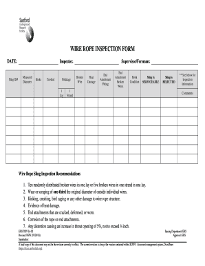
This report was prepared to serve as a guide for making thorough periodic examinations of wire ropes, sheaves and drums and serve asa permanent record of the inspection. One form should be used for each specific machine at each inspection.Before beginning an examination of an installation, fill in the blank spaces at the top of the report. These identify the company, equipmentlocation, machine number and the OEM equipment manufacturer and model. In addition, space is provided for the page number, date ofinspection and the name and signature of the inspector.The body of the report is split into three key sections allowing for separate reporting on ropes, sheaves and drums. Enough space isprovided to report on all the individual parts normally found on each piece of equipment. However, should additional space be requiredadd sheets and number each one appropriately.The individual columns have common and equipment specific information. The report can be filled in as follows:APPLICATION -
The removal criteria is specific to the rope/equipment type and local/federal regulations that apply.Specific design tolerances can be established by contacting the equipment and rope manufacturers.The equipment operator and inspector must confirm these before proceeding with an inspection (i.e.3 broken wires in one strand/lay length or 6 broken wires on one lay length).
Rope type includes any key identifying information (i.e. 3/4 6x25 EIPS RRL IWRC, Reel # - 4501001). Broken wires, measured diameter and lay length should be recorded based on the establishedcriteria and the recommended procedures laid out in this technical section. This information shouldbe identified and recorded for the worst locations on the rope. Additional damage can also belogged if it is a concern (i.e. Broken wires - drum 8 in one lay length, Measured diameter - drum .73,Lay length - drum 4.875). Drum spooling should be checked during operation, if damage has beenobserved, and comments noted (i.e. Crushing on the first layer and poor winding during operation).Specific damage deals with other potential problems not yet listed (i.e. Corrosion, kinks, cut wires orstrands, weld burns, etc).
This column allows the inspector to write specific notes, recommendations or out right rejection ofthe inspected item (i.e. Rope rejected due to damage at the drum, re-machine drum).
When an inspection is complete or has proceeded far enough for the inspector to reject the rope and or associated sheaves and drumsthe inspector should complete the form and sign the document. This document should then be kept on file for future reference. Refer tolocal or federal regulations to confirm the proper procedure for tracking and maintaining reports.Please note that this inspection report is also available on Micro Soft Excel. Please contact your Wire Rope Industries representative for acopy or contact our technical personnel on the Internet (www.wirerope.com).Back toTop
The occasional premature failure of a single wire may be found early in the rope life and in most cases it should not constitute a basis for rope removal. Note the area and watch carefully for any further wire breaks. Remove the broken ends by bending the wire backwards and forwards. In this way the wire is more likely to break inside the rope where the ends are left tucked away between the strands. These infrequent premature wire breaks are not caused by fatigue of the wire material.

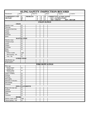
All inspections shall be performed by a designated person. Any deficiency identified shall be examined and a determination made by a qualified person as to whether it constitutes a hazard.
Prior to use, all new, altered, modified, or repaired slings shall be inspected to verify compliance with the applicable provisions of this Chapter. Written records are not required for initial inspection.
A complete inspection of the sling shall be performed. Inspection shall be conducted on the entire length including splices and fittings. Slings found with conditions such as those listed in Removal Criteria shall be removed from service. Slings shall not be returned to service until approved by a qualified person.
Liftex® strongly advises that slings displaying damage and subject to repair be evaluated by the manufacturer for suitability of said repairs. Damaged flat web slings should never be repaired. Hardware from damaged web or round-slings may besalvaged and re-webbed, subject to inspection of said hardware. Damaged components, sections or links of chain slings often times can be replaced and the sling put back into service. Any repairs shall be evaluated and performed by the manufacturer. Any repaired sling shall be proof-tested and documented prior to being put back

Wire rope is a collection of metal strands that have been twisted and wound to form the shape of a helix with the purpose of supporting and lifting heavy loads and performing tasks that are too rigorous for standard wire. On shipping docks, rigging, and load bearing equipment, wire rope is attached to swivels, shackles, or hooks to lift a load in a controlled, even, and efficient manner.
The uses for wire rope include adding support to suspension bridges, lifting elevators, and serving as additional reinforcement for towers. The design of wire rope, with its multiple strands wrapped around a stable core, provides strength, flexibility, and ease of handling for applications that have bending stress.
Individual designs of wire rope involve different materials, wire, and strand configurations as a means for supporting and assisting in the completion of lifting or supportive applications.
The term wire rope encompasses a wide range of mechanical tools that are made to perform heavy and extreme lifting jobs. Wire rope is a complicated and complex tool with multiple moving parts capable of moving in unison. A 6 by 25 wire rope has 150 outer strands that move as one in an intricate pattern supported by a flexible core.
An essential part of the design of wire rope is the required clearance between the strands to give each stand the freedom to move and adjust when the rope bends. It is this unique feature that differentiates wire rope from solid wire and other forms of cable.
The basic element of wire rope is wire that is used to configure, shape, and form the rope. Typically, steel, stainless steel, and galvanized wires are the first choice with aluminum, nickel alloy, bronze, copper, and titanium being second possibilities. The choice of wire is dependent on the type of work the wire is going to be used to perform with strength, flexibility, and abrasion resistance being the major determining factors.
Stainless steel wire rope has all of the basic qualities of galvanized and general wire rope with the added benefits of corrosion and rust resistance; this makes it the ideal choice for harsh and stressful conditions.
Steel wire rope is classified as general purpose wire rope and comes in a wide variety of sizes, diameters, and strengths. It is the most common type of wire rope and is used for several industrial, manufacturing, and construction applications.
Before going further into the discussion of how wire rope is made, it is important to understand the numbers used to describe each type. All wire ropes have a core around which wires are wound. The various styles of cores vary according to the construction and design of the requirements of the wire rope that is being produced.
Wire rope is classified by the number of strands it has as well as the number of wires in each strand. The most common classification is a seven wire rope that has one strand in the center and six around its circumference. This type of wire rope is lightweight with a very simple construction. The majority of wire ropes are more complex and intricate with multiple intertwining strands and wires.
What must be understood about wire rope is that it has a complicated configuration. It is actually wires wrapped around wires to form bundles that are wrapped around other bundles. In the case of a seven wire wire rope, the core has bundles of wires wound around it; this can be seen in the image below.
The first step in wire rope creation is the production of wire strands where wires are wound around a single core wire. The number of wires included in the strand is dependent on the specified strength, flexibility, and size requirements of the rope. Once the strand is completed, it is straightened before being moved to wire rope construction.
Like wire ropes, strands have different patterns; patterns are the arrangements of the wires and their diameters. Though most strands have a core, there are strand patterns that have three or four wires without a core that are referred to as centerless strands. The design of each strand pattern is meant to enhance the strength of the wire rope and improve its performance.
For a multiple layer strand, the layers of wire are placed over one another in successive order. The placement of the wires on top of each other must be such that they fit smoothly and evenly.
The Warrington pattern is like the multiple layer pattern with one variation. Like the multiple layer pattern, the inner wires and the core are the same and have the same diameter. The difference is in the outer layer, which has wires of alternating sizes of large and small with larger diameter wires laying in the valleys of the inner wires.
All of the wires of a filler pattern are the same size. What makes this pattern unique is the insertion of small wires in the valleys of the inner wires to fill the gap between the inner and outer layer.
The flattened strand pattern is also known as the triangular strand, which can be triangular or oval. Three round wires form the core. The outer flattened surface has a greater sectional metallic area; this makes this pattern stronger and longer lasting.
The core of a wire rope runs through the center of the rope and can be composed of a variety of materials, which include synthetic fibers, natural fibers, a single strand, or another wire rope. The core supports the wound strands, helps maintain their position, is an effective lubricant carrier, and provides support.
Wire ropes with fiber cores are restricted to light loads and are not used in severe, harsh, or stressful conditions. Polypropylene and nylon are types of synthetic fiber cores and can be used in conditions where there is exposure to chemicals.
Cores made of wire are classified as independent wire cores. The core of a wire rope with a wire core is actually a wire rope with another wire rope serving as the core, as can be seen in the diagram below. These types of wire ropes are used where the rope will be exposed to exceptional resistance and crushing.
A strand, or wire strand core, is exactly like the rest of the strands of the wire rope with wires of the same diameter and size as the other strands.
The choice of core and creation of the strands are the simplest yet most essential parts of wire rope construction. Wire rope lays, the method used to wind the strands, is more complex and involves several choices.
Lay is a term used to describe three of the main characteristics of wire rope: direction, relationship, and linear distance. The strands can be wrapped around the core going right or left. Right or left refers to the direction of the strands wrapped around the core and the wires within the strands. The linear distance is how far a strand moves when it is making a revolution around the core.
In a regular lay, the wires and strands spiral in opposite directions. With a right hand regular lay, the wires spiral to the left and the strands to the right. In the left hand regular lay, the wires spiral to the right and the strands to the left. This type of lay is easy to handle but wears out quickly because the crown wires are in contact with the bearing surface.
In the Lang, or Albert, lay, the wires and strands spiral in the same direction with right hand lay being the most common. The wires in a Lang lay appear to run parallel to the center line of the rope. The difficulty with Lang lay wire ropes is handling since they tend to kink, twist, and crush.
Wire rope is an exceptionally strong tool that has been configured and designed to withstand the stress placed upon it through rigorous and continual use. In most applications, wire rope has to endure extreme stress and strain. It is for these reasons that coatings have been developed to protect wire rope from abrasions, corrosion, UV rays, and harmful and damaging chemicals.
Three main types of coatings are used to protect wire rope: polyvinyl chloride (PVC), polypropylene, and nylon. Of the three types, PVC is the most popular.
In cases where there are severe and hazardous working conditions, polypropylene is the recommended choice since it is capable of protecting wire rope against corrosion and chemical leaching. Additionally, it is resistant to impact damage and abrasion. Polypropylene is a tough, rigid, and crystalline thermoplastic that is made from a propene monomer and is resilient as well as inexpensive.
Braided wires are electrical conductors made up of small wires that are braided together to form a round tubular braid. The braiding and configuration of braided wire makes them very sturdy such that they do not break when flexed or bent. Braided wires are widely used as conductors, are commonly made from copper due to copper"s exceptional conductivity, and can be bare or coated depending on the application.
Braided wire can be round and tubular or flat. Round tubular braids fit in most spaces where flat braided wire will not. Flat braided wire begins as round braided wire which is flattened on a capstan. They are exceptionally strong and designed for medical and aircraft applications.
Metals used to make wire rope are various grades of stainless steel, bright steel, and galvanized steel. Though the majority of wire rope manufacturers use these three metals, other metals such as copper, aluminum, bronze, and monel are also used on a limited basis.
The most important aspect of wire rope is the wire and the metal from which it is made. The strength and resilience of wire rope is highly dependent on the quality of metal used to make it, and these are essential factors to be considered when purchasing it.
Bright steel wire does not have a coating and is rotation resistant, (designed to not rotate when lifting a load). It is drawn from hot rolled rods that are put through a die to match its specific dimensional tolerances, mechanical properties, and finish. Bright wire is used as a single line in conditions that require a rope that will resist cabling.
Galvanized steel has a zinc coating for corrosion resistance and has the same strength and durability as bright steel. Environmental conditions determine the use of galvanized steel. In mildly severe and slightly harsh conditions, galvanized steel wire is an economical replacement for stainless steel.
In the manufacturing process, galvanized wire goes through the process of galvanization, a method of coating steel wire with a protective and rust resistant metal. Galvanized wire is exceptionally strong, rust resistant, and flexible enough to meet the needs of a variety of applications.
Wire rope made from copper is mostly used for electrical applications due to its exceptional electrical characteristics. The benefits of copper wire rope are its durability, flexibility, and resilience compared to standard copper wire. The strength of copper wire rope is seen in its use in applications where there are vibrations and shaking.
The wire rope lubrication process begins during its fabrication and continues during its use. Lubrication of wire rope is designed to lower the amount of friction it endures and provide corrosion protection. Continued lubrication increases the lifespan of wire rope by preventing it from drying up, rusting, and breaking.
The types of lubricants for wire rope are penetrating or coating with coatings covering and sealing the outside of the rope. Penetrating lubricants go deep into the rope and seep into the core where they evaporate to form a thick coating or film.
The application of the lubricant is dependent on the type of core. Fiber cores absorb the lubricant and serve as a reservoir that retains the lubricant for an extended period of time. With metal cores, the lubricant is applied as the wire is twisted into strands to give complete saturation and coverage of the wires.
There are several types of greases that are used as wire rope lubricating agents and are made up of oil, a thickener, and additives. The essential components are the base oil and additives, which influence the behavior of the grease. The thickener holds the base oil and additives together. The amount of base oil in a grease is between 70% and 95% with an additive of 10%.
The additive in grease enhances the positive properties of the oil and suppresses the negative properties. Common additives are oxidation and rust inhibitors as well as pressure, wear, and friction reducing agents.
Of the many choices for lubricants, vegetable oil is the easiest to use and penetrates the deepest. The design of the additives for vegetable oils gives them the necessary qualities required to penetrate deep into a wire rope. The exceptional penetration provides protection against wear and corrosion. Since vegetable oil is a fluid, it helps in washing the wire rope to remove external abrasive contaminants.
Wire rope is widely used in machines, structures, and varied lifting applications. Its type, size, and requirements are determined by how it will be used. Regardless of its use, wire rope guarantees exceptional strength and provides high quality and excellent performance.
The lifting of heavy loads for centuries involved the use of hemp rope or chains, neither of which was a guaranteed or substantial method. Early in the 18th Century, between 1824 and 1838, Wilhelm Albert, a German mining engineer, combined the twisting of hemp and strength of chains to create today‘s wire rope.
The most common use of wire rope is as a part of a crane hoist wherein it is attached to the hook of the hoist and wrapped around a grooved drum. The tensile strength and durability of wire rope makes an ideal tool for lifting and keeping loads secure. Though it is used in several industries, it is very popular for production environments wherein materials need to be lifted quickly and efficiently.
In addition to its many lifting applications, the strength and stability of wire rope is useful in other applications, especially in the aerospace industry. Pedals, levers, and connectors in the cockpit of an aircraft are connected with wire rope. The wires provide for the passage of power between systems and mechanisms; this allows control of the aircraft. Wire rope is used to control propeller pitch, cowl flaps, and the throttle. It also assists in lowering and minimizing vibrations.
Tires are reinforced with wire rope to increase their durability and strength. All automotive production environments make use of wire ropes for supplying materials, moving heaving loads, and positioning equipment. Wire rope can be found in the production of steering wheels, cables, exhausts, springs, sunroofs, doors, and seating components.
As surprising as it may seem, the place that wire rope has the greatest use is in the home, where its strength, long life, endurance, and resilience provide guaranteed protection and performance. The main reason wire ropes are so popular for home use is cost.
Inexpensive, easy to obtain, easy to install, and easy to maintain, wire ropes provide an additional method for performing home repairs and structural support. Their excellent flexibility and sturdiness combined with their invisibility has made wire rope an ideal solution to several home maintenance issues. It is used to support staircases, fences, decks, and hang plants.
The search and production of crude oil has relied on wire ropes for centuries to lift drill bits, insert shafts, and support oil rigs on land and the water. When equipment, machinery, and tools have to be lowered into the depths of the earth and sea, wire ropes are the tool that the oil industry relies on to do the job.
Many of the tasks of oil production require tools that are capable of enduring severe and harsh conditions. Wire ropes have to withstand enormous pressure, extraordinary stress, and a wide range of temperatures. The use of wire rope includes maintaining oil rig stability and moorings for offshore rigs.
Wire rope has long been a standard component for the transportation industry, from the cable cars of San Francisco to the lift chairs for ski resorts. For many years, cable cars have relied on heavy duty cables (wire ropes) to be pulled by a central motor from multiple locations. It is a method of transportation that has existed for centuries.
In Europe, funiculars use cables that hang from a support to move cars up and down a mountain with cables moving in opposite directions. The word funicular is from the French word funiculaire, meaning railway by cable. The terms wire rope and cable are used interchangeably when discussed by professionals. The first part of funicular, or funiculaire, is from the Latin word "funis," meaning rope.
The major use for wire ropes in the food and beverage industries is as a means for lifting and moving heavy loads. Wine barrels and containers full of ingredients are lifted and placed through use of cranes and wire ropes. They are also part of conveyor systems that move products from one station to another.
From the beginnings of amusement rides up to the present, wire ropes have been an essential part of attraction construction and safety. They pull cars on roller coasters, hold cabins that swing, and move carriages through haunted houses. The main concern of amusement parks is safety. The strength, stability, and guaranteed performance of wire ropes ensures that people who attend amusement parks will have a good time and stay safe.
The rigging used to complete the stunts in modern movies depends on wire rope for safety. Much like in amusement rides, wire ropes protect performers from injury and harm as they hang above a scene or carry out an impossible move.
The live theater industry uses wire ropes to raise and lower curtains, support overhead rigging, and hold backdrops and scenery pieces. During a production, rapid and efficient movement is a necessity that is facilitated by the use of wire ropes.
Wire rope is a tool that we tend to envision as indestructible, unable to succumb to any form of damage. Though it is exceptionally sturdy and strong as well as capable of enduring constant use, it is just as susceptible to breakdown as any other tool.
To avoid serious harm and damage, wire ropes should be scheduled for regular inspections. There are situations that can damage or break a wire rope; these should be understood prior to the problem arising.
Guide rollers have the potential to damage and cause abrasions on wire rope if they become rough and uneven. Of the various elements of a crane and lift, guide rollers have the greatest contact with the mechanism‘s wire rope. Regular inspection of guide rollers will ensure they are not damaging the rope or causing abrasions.
Bending is normally a regular part of wire rope usage; this occurs repetitively as the rope passes through a sheave. As a wire rope traverses the sheave, it is continually bent and develops cracks or breaks. The cracking and breaking are exacerbated by movement on and off the groove of the drum. Normally, the breakage happens on the surface and is visible. Once it appears, it accelerates to the core of the rope.
A bird cage is caused by a sudden release of tension and a rebound of the rope. This type of break requires that the rope be replaced since the place of the break will not return to its normal condition.
Wire ropes are multi-layered; this makes them flexible and torque balanced. The layering inside and outside creates flexibility and wear resistance. Relative motion between the wires causes wear over time, which leads to internal breakage. The detection of these breaks can be indicated by an electromagnetic inspection that calculates the diameter of the rope.
Kinked wire rope is caused by pulling a loop on a slack line during installation or operation; this causes a distortion in the strands and wires. This is a serious condition that necessitates rope replacement.
Corrosion damage is the most difficult cause of wire rope damage to identify, which makes it the most dangerous. The main reason for corrosion is poor lubrication that can be seen in the pitted surface of the rope.
The types of damage and problems listed here are only a small portion of the problems that can be caused if a wire rope is not regularly lubricated and inspected. Various regulatory agencies require that wire ropes be inspected weekly or monthly and provide a list of factors to examine.
As with any type of heavy duty equipment, wire rope is required to adhere to a set of regulations or standards that monitor and control its use for safety and quality reasons. The two organizations that provide guidelines for wire rope use are the American Society of Mechanical Engineers (ASME) and the Occupational Safety and Health Administration (OSHA).
All wire rope manufacturers and users closely follow the standards and guidelines established by OSHA and ASME. In the majority of cases, they will identify the specific standards they are following in regard to their products.
OSHA‘s regulations regarding wire rope fall under sections 1910, 1915, and 1926, with the majority of the stipulations listed in 1926 under material handling, storage, use, and disposal.
"Running rope in service shall be visually inspected daily, unless a qualified person determines it should be performed more frequently. The visual inspection shall consist of observation of all rope that can reasonably be expected to be in use during the day‘s operations. The inspector should focus on discovering gross damage that may be an immediate hazard."
"The inspection frequency shall be based on such factors as rope life on the particular installation or similar installations, severity of environment, percentage of capacity lifts, frequency rates of operation, and exposure to shock loads. Inspections need not be at equal calendar intervals and should be more frequent as the rope approaches the end of its useful life. Close visual inspection of the entire rope length shall be made to evaluate inspection and removal criteria."
ASTM A1023 covers the requirements for steel wire ropes with specifications for various grades and constructions from ¼ in. (6 mm) to 31/2 in. (89 mm) manufactured from uncoated or metallic coated wire. Included are cord products from 1/32 in. (0.8 mm) to 3/8 in. (10 mm) made from metallic coated wire.
United States Federal Spec RR W 410 covers wire ropes and wire seizing strands but does not include all types, classes, constructions, and sizes of wire rope and strands that are available. The purpose of Spec RR W 410 is to cover more common types, classes, constructions, and sizes suitable for federal government use.
Wire rope and wire seizing strand covered by United States Federal Spec RR W 410 are intended for use in general hauling, hoisting, lifting, transporting, well drilling, in passenger and freight elevators, and for marine mooring, towing, trawling, and similar work, none of which are for use with aircraft.
API 9A lists the minimum standards required for use of wire rope for the petroleum and natural gas industries. The types of applications include tubing lines, rod hanger lines, sand lines, cable-tool drilling and clean out lines, cable tool casing lines, rotary drilling lines, winch lines, horse head pumping unit lines, torpedo lines, mast-raising lines, guideline tensioner lines, riser tensioner lines, and mooring and anchor lines. Well serving wire ropes such as lifting slings and well measuring are also included in API 9A.
Wire rope is a collection of metal strands that have been twisted and wound to form the shape of a helix with the purpose of supporting and lifting heavy loads and performing tasks that are too rigorous for standard wire.
Individual designs of wire rope involve different materials, wire, and strand configurations as a means for supporting and assisting in the completion of a lifting or supportive task.


 8613371530291