
wire rope inspection standard free sample

A competent person must begin a visual inspection prior to each shift the equipment is used, which must be completed before or during that shift. The inspection must consist of observation of wire ropes (running and standing) that are likely to be in use during the shift for apparent deficiencies, including those listed in paragraph (a)(2) of this section. Untwisting (opening) of wire rope or booming down is not required as part of this inspection.
Significant distortion of the wire rope structure such as kinking, crushing, unstranding, birdcaging, signs of core failure or steel core protrusion between the outer strands.
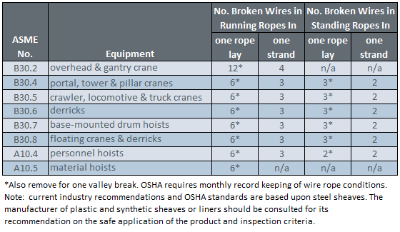
In running wire ropes: Six randomly distributed broken wires in one rope lay or three broken wires in one strand in one rope lay, where a rope lay is the length along the rope in which one strand makes a complete revolution around the rope.
In rotation resistant ropes: Two randomly distributed broken wires in six rope diameters or four randomly distributed broken wires in 30 rope diameters.
In pendants or standing wire ropes: More than two broken wires in one rope lay located in rope beyond end connections and/or more than one broken wire in a rope lay located at an end connection.
If a deficiency in Category I (see paragraph (a)(2)(i) of this section) is identified, an immediate determination must be made by the competent person as to whether the deficiency constitutes a safety hazard. If the deficiency is determined to constitute a safety hazard, operations involving use of the wire rope in question must be prohibited until:
If the deficiency is localized, the problem is corrected by severing the wire rope in two; the undamaged portion may continue to be used. Joining lengths of wire rope by splicing is prohibited. If a rope is shortened under this paragraph, the employer must ensure that the drum will still have two wraps of wire when the load and/or boom is in its lowest position.
If a deficiency in Category II (see paragraph (a)(2)(ii) of this section) is identified, operations involving use of the wire rope in question must be prohibited until:
The employer complies with the wire rope manufacturer"s established criterion for removal from service or a different criterion that the wire rope manufacturer has approved in writing for that specific wire rope (see § 1926.1417),
If the deficiency is localized, the problem is corrected by severing the wire rope in two; the undamaged portion may continue to be used. Joining lengths of wire rope by splicing is prohibited. If a rope is shortened under this paragraph, the employer must ensure that the drum will still have two wraps of wire when the load and/or boom is in its lowest position.
If the deficiency (other than power line contact) is localized, the problem is corrected by severing the wire rope in two; the undamaged portion may continue to be used. Joining lengths of wire rope by splicing is prohibited. Repair of wire rope that contacted an energized power line is also prohibited. If a rope is shortened under this paragraph, the employer must ensure that the drum will still have two wraps of wire when the load and/or boom is in its lowest position.
Where a wire rope is required to be removed from service under this section, either the equipment (as a whole) or the hoist with that wire rope must be tagged-out, in accordance with § 1926.1417(f)(1), until the wire rope is repaired or replaced.
The inspection must include any deficiencies that the qualified person who conducts the annual inspection determines under paragraph (c)(3)(ii) of this section must be monitored.
Wire ropes on equipment must not be used until an inspection under this paragraph demonstrates that no corrective action under paragraph (a)(4) of this section is required.
At least every 12 months, wire ropes in use on equipment must be inspected by a qualified person in accordance with paragraph (a) of this section (shift inspection).
The inspection must be complete and thorough, covering the surface of the entire length of the wire ropes, with particular attention given to all of the following:
Exception: In the event an inspection under paragraph (c)(2) of this section is not feasible due to existing set-up and configuration of the equipment (such as where an assist crane is needed) or due to site conditions (such as a dense urban setting), such inspections must be conducted as soon as it becomes feasible, but no longer than an additional 6 months for running ropes and, for standing ropes, at the time of disassembly.
If the deficiency is localized, the problem is corrected by severing the wire rope in two; the undamaged portion may continue to be used. Joining lengths of wire rope by splicing is prohibited. If a rope is shortened under this paragraph, the employer must ensure that the drum will still have two wraps of wire when the load and/or boom is in its lowest position.
If the qualified person determines that, though not presently a safety hazard, the deficiency needs to be monitored, the employer must ensure that the deficiency is checked in the monthly inspections.
All documents produced under this section must be available, during the applicable document retention period, to all persons who conduct inspections under this section.
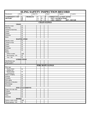
Maintain a record for each rope that includes the date of inspection, type of inspection, the name of the person who performed the inspection, and inspection results.
Use the "rag-and-visual" method to check for external damage. Grab the rope lightly and with a rag or cotton cloth, move the rag slowly along the wire. Broken wires will often "porcupine" (stick out) and these broken wires will snag on the rag. If the cloth catches, stop and visually assess the rope. It is also important to visually inspect the wire (without a rag). Some wire breaks will not porcupine.
Measure the rope diameter. Compare the rope diameter measurements with the original diameter. If the measurements are different, this change indicates external and/or internal rope damage.
Visually check for abrasions, corrosion, pitting, and lubrication inside the rope. Insert a marlin spike beneath two strands and rotate to lift strands and open rope.
Assess the condition of the rope at the section showing the most wear. Discard a wire rope if you find any of the following conditions:In running ropes (wound on drums or passed over sheaves), 6 or more broken wires in one rope lay length; 3 or more broken wires in one strand in one rope lay. (One rope lay is the distance necessary to complete one turn of the strand around the diameter of the rope.)
Corrosion from lack of lubrication and exposure to heat or moisture (e.g., wire rope shows signs of pitting). A fibre core rope will dry out and break at temperatures above 120°C (250°F).
Kinks from the improper installation of new rope, the sudden release of a load or knots made to shorten a rope. A kink cannot be removed without creating a weak section. Discarding kinked rope is best.

Lifting slings are one of the most versatile rigging and lifting equipment. While slings have been around for centuries, their industrial use began only a few decades ago. Today, industrial slings are made from synthetic fibers like polyester, nylon, or high-performance materials. You will also see wire rope slings made from high-grade steel or iron.
Slings play a critical role in handling and transporting heavy loads. That’s why, when it comes to lifting slings, safety needs to be the topmost concern. You can’t ensure safe material handling without sling inspection before use. Moreover, these inspections should meet or exceed the prescribed standards.
The American Society of Mechanical Engineers or ASME has set standards for industrial lifting and rigging equipment of all shapes and sizes. The ASME B30.9 standard specifically deals with load-handling lifting slings. It covers everything about lifting slings, including:Attachment
The standard applies to everyone, including manufacturers, suppliers, owners, and users. If you are one of them, you will also want to confer to this standard. ASME keeps updating the standard every few years.
Adhering to the ASME B30.9 standard brings you several benefits. When it comes to buying, using, and maintaining lifting slings, this standard is a must. And here’s why.
For example, the ASME B30.9 standard clearly states that if a sling meets the following conditions, you should remove it from service immediately.Bird Caging
The standard also talks about manufacturing, assembling, and fabrication guidelines for lifting slings. In other words, AMSE lifting slings are thoroughly vetted. They also meet the quality and safety standards prescribed by the B30.9 code.
This standard also talks about maintaining lifting slings in excellent condition. Maintenance is necessary to ensure safety and long shelf life. While synthetic web or round slings are not expensive, large wire rope slings cost hundreds of thousands.
As mentioned before, ASME keeps updating all of its standards periodically. For ASME B30.9, the latest changes came into effect in 2021. That said, Holloway Houston prides itself in conferring to these latest revisions. Here’s a short synopsis of the latest changes made to the ASME B30.9 – 2021.
Taking the compliance of ASME B30.9 for granted is a mistake. ASME standards, B30.9 included, are not mandatory. ASME cannot force any manufacturer, inspector, or installer to follow ASME standards.
As you can see, standards like ASME B30.9 play a critical role in ensuring the safety, quality, and maintenance of lifting slings. When you are out shopping for these industrial lifting devices, you have to make sure to understand what this standard means, how it works, and why you need to consider it. Hopefully, this short post will shed some light in this regard.
Wire ropes are widely employed components in diverse areas, such as in industrial production, tourist cable cars, mining, metallurgy, shipbuilding, and elevators. Wire rope is a heavily loaded component, and long-term continuous operation eventually result in corrosion, wear, broken wires, loose wires, and fatigue, which decrease the loading strength of the rope, and can cause accidents, resulting in property damage and injury [1]. The traditional damage detection method is artificial visual inspection, which is a low efficiency, time-consuming, and unreliable method [1]. The development of a fast, non-destructive, and automatic detection technology is therefore necessary.
Wire rope defects include three main types: the loss of metallic area (LMA), local faults (FLs), and structural faults (SFs). The main non-destructive testing (NDT) methods employed for wire rope inspection include electromagnetic detection, ultrasonic guided wave (UGW) evaluation, radiation testing, eddy current inspection, and optical detection [1]. However, designing a precise detection device that can quantitatively determine the characteristics of defects, such as the number of broken wires, remains problematic, particularly when operating in severe environments [2].
The UGW method has been shown to provide a detection speed that is faster than other methods, but the method demonstrates a low anti-interference ability and suffers from strong background noise [3,4,5,6,7]. Treyssède and Laguerre’s [3] applied the transmission characteristics of UGW for wire rope testing. The researchers developed a semi-analytical finite element method, and calculated the optimal excitation and receiving sites. This approach provided a wave dispersion curve for spiral steel rope. Vanniamparambil [4] proposed a novel detection method that combined three technologies: UGW, acoustic emission techniques, and digital image processing. Xu [7] evaluated the detection precision of the UGW method for wire rope defects obtained at different frequencies, showing that wire ropes at higher frequencies had longer recovery lengths for their elastic waves. Raisuitis [5] investigated the propagation of UGWs along composite multi-wire ropes with various types of acoustic contacts between neighboring wires and the plastic core. Tse and Rostami [6] investigated the efficiency of employing the magnetostriction of ferromagnetic materials in conjunction with the UGW method for wire rope defect inspection, and the location and severity of defects were approximately identified and characterized using the short-time Fourier transform and wavelet analysis. Other detection methods, such as radiation testing [8] and eddy current inspection [9], have not been applied to wire rope inspection to a large extent.
Electromagnetic detection methods are commonly employed for the NDT of wire rope [2]. The basic principle behind wire rope electromagnetic detection is illustrated in Figure 1. The lower permeability of the air leads to magnetic field leakage (MFL) from the rope defect, and the strength of the MFL can be obtained from an appropriately designed magnetic detection device. In terms of the type of excitation source employed, electromagnetic detection can be divided according to the use of a coil [10,11] or a permanent magnet [12,13,14,15,16,17] for generating a magnetic field. Modified main-flux equipment has been developed for wire rope inspection, which induced changes in the electromagnetic field strength owing to the leakage field derived from defects in various large-diameter wire ropes [10]. Other researchers [11] employed a pair of saddle coils for the magnetization of a steel track rope, and this system was applied to detect small, inner flaws in the rope. Permanent magnets have been employed in a saddle structure to saturate wire rope in a uniform magnetic field [14,15,16,17]. Wang et al. [12] investigated the effect of excitation distance and the lift-off distance between the sensors and the wire rope surface on the detection precision. The researchers accordingly modified the magnetic circuit of the detector to restrain the impact of fluctuations in the sensor lift-off distance. Xu et al. [18] developed a magnetic excitation model. Based on this model, the researchers established design criteria for the size of the excitation structure, proposed a theoretical framework for the excitation structure size based on numerical analysis, and adjusted the theoretical design using finite element analysis (FEA).
Obtaining a precise MFL signal is the most important aspect for the accurate electromagnetic NDT of wire rope. For MFL signal acquisition, a commonly employed in-service NDT method utilizes an induction coil [10,17], Hall effect sensor [14,18,19,20,21], giant magnetoresistive (GMR) sensor [11,22], and tunnel magnetoresistive (TMR) sensor [23]. Jomdecha and Prateepasen [10] modified a conventional induction coil into a coil array that densely covered the wire rope to acquire the MFL signal. Wang and Tian [14] utilized FEA to address the problems associated with the weak MFL signals derived from small defects, and they investigated the gathered magnetism of the magnetization rope. They designed a detector with an annular pole polymagnet on one side using Hall elements as inductors. This detection system was able to capture weak MFL signals within the strong magnetic field. Xu and Wang [18] developed an online modular-detector NDT system using a Hall effect sensor that successfully detected inner broken wires. The researchers also presented three filtering algorithms. Detectors based on Hall effect sensor arrays have been widely applied for NDT under strong magnetic field conditions [19,20,21]. Cao [19] created an image from the defect data which was obtained by Hall sensors array, and applied digital image processing to extract and detect defect characteristics. Zhang et al. [20] employed signal processing to suppress the effect of lift-off distance, and applied statistical processing to distinguish different types of defects and to obtain binary image data describing the spatial extent of defects. Zhang et al. [21] applied a space filter to suppress the texture of strand waves after obtaining MFL gray-level images of wire rope defects, and the image spectrum texture was extracted as the characteristic vector used for recognition. GMR sensors have been employed for MFL signal acquisition because of their high sensitivity, high precision, and small size. GMR sensors were placed into a sensor array and densely distributed on the wire rope surface in a manner similar to that employed in a Hall effect sensor application [11]. Zhang and Tan [22] utilized the high sensitivity of a GMR sensor to develop a detection technique based on remanence magnetization, which combined the benefits of a simple structure and high detection speed with high precision. Wu et al. [23] demonstrated that TMR sensors can be applied to detect small discontinuities on a wire rope surface.
MFL signals contain a variety of distinct noise signals, which makes the development of an efficient de-noising algorithm challenging work. Currently, a number of noise reduction algorithms are commonly employed, including wavelet analysis de-noising, low-pass filter, notch filter [21], adaptive filter [20], morphological filter [24], and a de-noising algorithm based on compressed sensing (CS) [22]. Zhang et al. [20] applied digital image processing to develop a space filter for smoothing the defects in an MFL signal image. Zhang et al. [21] proposed a baseline estimation algorithm to suppress the effect of undulations in the lift-off distance and an adaptive notch filtering algorithm to filter the strand wave for increasing the signal-to-noise ratio. Zhang and Tan [22] utilized wavelet multi-resolution analysis to eliminate the baseline of the signal. Their work was based on the CS wavelet de-noising algorithm, and they calculated the best sparse transform expression to completely filter out the noise. Tian et al. combined the wavelet transform and the morphological transform to create a morphological filter algorithm that suppressed the interference associated with the baseline drift in the wire rope signal. Artificial neural networks have been widely applied to realize the quantitative detection of wire rope defects. These networks operate much like back propagation (BP) neural networks employed by a number of researchers [20,21,22]. However, BP neural networks suffer from some limitations and shortcomings, such as poor generalization and slow convergence.
Devices based-on the x-ray method are generally bulky, heavy, and suffer from high maintenance costs, and furthermore, it is difficult to accurately locate defect positions with the UGW detection method, which suffers from external disturbances and limited detection length. The eddy current inspection method is difficult to apply in practice for producing coils on-site, and the system is difficult to manage. However, conventional electromagnetic NDT typically utilizes a large, heavy excitation device as well. Moreover, extracting defect information from the induction coil is difficult, and, in addition, the sensitivity of Hall effect sensors is low. Conventional digital filter algorithms cannot adequately suppress the noise in the MFL signal. This limited ability to reduce noise makes it difficult to separate the defect signal and the strand wave under low signal-to-noise ratio conditions while processing the signal.
To overcome the disadvantages of existing detection devices, we developed a prototype device based on the RMF of a wire rope. This inspection method utilizes GMR sensors for excitation signal acquisition. After magnetizing the wire rope with permanent magnets, the GMR sensor array was utilized to obtain the RMF strength of the rope surface. This detection system is non-contact and non-invasive which prolongs the service life of test equipment. A novel filter algorithm based on the Hilbert-Huang transform (HHT) and compressed sensing wavelet filtering (CSWF) was developed to suppress the various system noises. The HHT was employed to remove the DC component of the signal and balance the sensor channels. CSWF was employed to suppress high-frequency noises and strand waves. Then, we applied digital image processing to create a binary image using a filter based on corrosion and expansion. Subsequently, defects were located and segmented within the gray-level image. Because an 18 GMR sensor array was employed, the resulting gray-level image included only 18 pixels in its circumference. Three spline interpolations were performed to improve the circumferential resolution of the gray-level image. Thirteen image characteristics comprising 6 image textures and seven invariant moments were extracted as defect feature vectors. A radial basis function (RBF) neural network, which is a fast-learning classification network that provides a global optimum, was adopted to quantitatively detect the number of broken wires in the rope. Experimental results demonstrate that, when the absolute limiting error for the detected number of broken wires is 2, the recognition rate is as high as 93.75% with an average recognition error of 0.7813 wires.

Need a quick overview on the proper inspection of a wire rope sling? How about a just a quick refresher for your team? Never fear, ITI is here to help you out! Follow along with ITI Co-Founder and Technical Director, Mike Parnell. You will be hard pressed to make better use of five minutes, although if you think you have something good be sure to mention it in the comments.
Pretty good stuff right? I know it seems too good to be true, but here is one more wire rope inspection resource "for the road." Download a free copy of a sample wire rope inspection form below!


 8613371530291