
wire rope isolators damping free sample

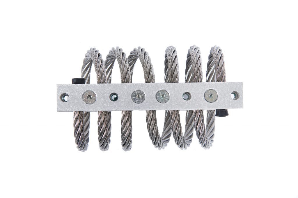
Look to Enidine for high performance Wire Rope Isolators and Compact Wire Rope Isolators. The wire rope isolators have stainless steel cable and RoHS compliant aluminum retaining bars, which provides excellent vibration isolation. The isolators are corrosion resistant, which makes them environmentally stable and high-performance in a variety of applications. The isolators are completely unaffected by oil, chemicals, abrasives, ozone, and temperature extremes.
The compact wire rope isolator is smaller than a traditional wire rope and can absorb shock and vibration in small spaces. Single point mounting offers flexibility for integration into existing products.
Both compact wire rope isolators and wire rope isolators can be used on galley components where motors and fans produce vibrations onto surrounding structures. They can also be used to control vibration and thermal expansion.
To ensure safe and continuous operation, or for instance flawless and safe transport of (highly) sensitive equipment, adequate shock and vibrationprotection is essential. The adequate level of protection is typicallypredominated by combining the appropriate shock mounts, thoroughcalculation and understanding of the application. The advantage of a wire rope isolators (WRI)lies in its ability to combine a high levelof isolation while taking up relatively little space. WRI are captive by theirconstruction and may, for this reason, be loaded in any direction withoutthe risk of malfunctioning. WRI are not subject to aging due to externalfactors such as oil, saltwater, chemicals, and heat or cold. Mostapplications of WRI can be found in situations where equipment needs tobe mounted against shocks or vibration, but where sound isolation is ofminor importance.
The vibration and noise emitting from the machines and equipment in operation may appear to be harmless on the surface. The people may get perturbed by the noise but may get used to working in the noisy industrial environment over a period of time. However, vibration and noise are the most destructive agents in the industrial environment and their effects are known in the form of machine breakdowns, fatigue failures, and health deterioration in human beings. By the time we realize these damages it is already too late. Products in the form of vibration wire rope isolators and rubber vibration dampening mounts are available today to stem the vibrations and prevent them from causing damage. Let us look at these products.
Wire cable isolators: The vibration isolation wire rope plays the crucial role in the selection of the right kind of isolator for the equipment. If you choose the right wire
characteristics like the wire diameter, number of strands, wire length, wire twist, and the number of strands per section you can get the wire isolator that is most suited for your requirement. Sufficient literature is available onsite to help you make this choice. It is right to call them as wire rope insulators as they shield the equipment from the harmful effects of vibration. As a passive vibration insulation system, the wire isolators require no maintenance, occupy little space, and perform even in changing temperature conditions and harsh environments.
Rubber mounts and isolators: The rubber mounts for vibrations are crucial components in the machinery and equipment, and help in dampening the noise levels and vibrations while safeguarding the sensitive parts from the impact of the external vibrations.
Rubber shock mounts: The shock mount type rubber vibration isolator is designed to absorb shock for static equipment. Another product in the rubber vibration isolation mounts category is suitable for the marine application such as propulsion engines and diesel generator sets where damping of low frequencies is required.
As a leading rubber mount manufacturer, Andre HVAC International Inc. has led the way to develop solutions to isolate vibrations and reduce noise over the past 13 years. They not only have a wide range of wire rope ISO mounts and rubber vibration isolation mountsbut also partner with you in developing a new application or capitalizing on their existing technology. You can be sure of finding the answer to your vibration damping needs from them.

The reasonable conclusion from the previous results referring to the effect of directional arrangement of isolator systems was to investigate how on compression stiffness of wire rope isolator systems influences lateral shear accompanying to free compression. Lateral shear and rolling phenomena appearing during free compression of wire rope isolators were further analyzed experimentally. In source literature where wire rope isolator compression tests have been broad described, the shear phenomenon influence is often omitted due to the testing stand construction that features one-directional loading pass as in strength testing machines. Contrary to test conditions described in many studies, in this paper are assumed conditions of free compression, which referred rather to investigate of combined stress states.
The aim of further investigations was to determine static and dynamic characteristics of two configuration, namely “parallel” and “serial”, each consisting of two isolators. It was assumed that Y axis of coordinates is parallel to the isolators of the central axes, and Z axis is perpendicular to the surfaces of the upper and the lower plates as shown in Figure 8.
Figure 9 presents changes of the upper plate lateral displacements (along Y axis) perpendicular to the vertical loading direction Z during cyclic down and up 5 kg load tests carried out on “parallel” configuration of two wire rope isolators. Similar characteristics were obtained for the second lateral direction X, but the range of displacement changes was less than those for Y direction. It was additionally noticed that vertical, symmetry axis of the upper plate was subjected to a small angle deviation what can cause instability of the whole system in extreme case. Dangerous of loss of stability is greater for “serial” than for “parallel” configuration.
Figure 10 shows a comparison of displacements in vertical Z direction for two different configurations. The upper plate of the stand was loaded by masses in the following order: 5.88, 2.27, 1.35, 1, 0.94, 0.76, 0.74, and 0.49 kg. It can be noticed that at “serial” configuration, a set of isolators increasing the vertical displacement is higher than those at “parallel” configuration. In addition, in case of “serial” configuration, after adding the mass of 0.94 kg, the loss of stability occurred.
Only “parallel” configuration of two isolators was further considered. There were determined hysteresis loops to identify average static stiffness characteristics similarly as before for “star” and “triangle” configurations but previously consisting of three isolators. The main reason for authors was looking for an answer for a question if it would be correct to apply additivity theorem to static stiffness measured in vertical direction despite identified lateral deflection influences. An exemplary hysteresis loop obtained in quasi-static successive uploading and unloading process carried out on “parallel” configuration of two isolators is presented in Figure 11. The identified average static stiffness characteristic was evaluated using LSQ method.
In engineering practice, it is required to compare static stiffness characteristics made for different configurations and different numbers of isolators in the same chart, considering the number of supporting isolators under the assumption that additivity property is acceptable. It was done here, and the result shown in Figure 12 is a sort of proof that such assumption was correct in case of using wire rope isolators.

People who are aware of the damage caused by vibrations always include anti-vibration products in their portfolio, whenever they are creating a new infrastructure or installing a new machine or a piece of equipment. The preference is always been for products that are fit and forget type, requiring the least possible maintenance and care. One such product is the nimble wire rope isolator anti-vibration mount. The product is very rugged and a silent performer.
The wire isolators exhibit non-linear stiffness behavior. The type of deflection will help in the selection of the wire rope insulators. The spring rate is different for larger shock deflections and small deflections. The average stiffness values of the wire isolators for full loop versions are normally listed on the website or catalogues. The damping values are typically around 10 per cent, depending on the input level and size. In the case of unstable high structures, it is recommended to use stabilizers. A typical example is a piece of equipment where the height is more than twice the base width.
In the places where there is a limitation of space, the compact wire rope isolators provide the ideal solution. As the name suggests, these vibrationwire rope isolators provide the cost-efficient, shock and vibration isolation in cringed spaces. The single point installation makes it easy for the compact wire rope isolators to be installed in precise and sensitive applications like electronics and lab equipment. The compact vibration wire rope isolators provide the adequate reliability that is unaffected by temperature or substrate requirements.
The wire rope isolator CAD models are available for download from a number of websites. It is also possible to join forums for the model downloads. The CAD modeling makes it easy to select the wire rope isolator suited for the required application. The armed forces have the requirement of the wire rope isolator for vibration damping in rough terrains and in heavy-duty applications. They can counter the impacts from collisions and poor road conditions. You will also find them in shipping containers, aircraft, and medical equipment etc. While in the air they can withstand high-G maneuvering, turbulent air and hard landings. The wire cable isolators are free from creeping or ageing and have a long lifespan. It is also possible to do quick and economical prototyping for specific requirements.
The wire rope isolator anti-vibration product can be used in a variety of load conditions that include compression, shear, and rolling mode etc. The wire isolators also withstand the combination of loads like the 45-degree compression and rolling. The cable that is looped through the retaining bars is responsible for the elasticity in the wire rope isolators giving it the spring function. On the other hand, the relative friction between the strands of the wire rope provides the damping function in thewire rope isolator. To get the right kind of performance and for proper selection of the wire rope isolator for vibration damping, it is important to understand the spring behavior and damping function.
Andre HVAC International Inc. is a leading supplier of a diversified range of wire rope isolators for vibration damping. It provides customized technology solutions and highly engineered wire rope isolators for the growing industrial markets in the world. The solutions from AHI are well accepted and recognized as the preferred products for vibration isolation. The customized solutions have performed well in challenging applications and harsh industrial environments.

A series of periodic loading experiments were carried out on the O-type wire-cable vibration isolators. The isolators were loaded under shear, roll, and tension-compression loadings. When subjected to shear and roll loads, the restoring force-deformation curves generated by the isolators formed symmetric hysteresis loops. However, when the isolators were loaded with tension-compression loads, the isolator produced asymmetric hysteresis loops. It is found through the experiment that the dynamic characteristics of the isolator are determined by the loading amplitude as well as the geometric parameters of the isolator while they are almost independent of loading frequency within the testing frequency range. Based on the experimental data, the dynamic response of the isolator was modeled by a modified normalized Bouc-Wen model. The parameters of this model were identified through an identification procedure that does not involve any nonlinear iterative algorithms. Comparison between the identification results and the experimental data suggests that the identification method is effective. With the model and the identified parameters, the frequency response of an O-type wire-cable vibration isolator-mass system was evaluated. Typical nonlinear response behaviors were found when the isolator was used in tension-compression mode while the response appears to be similar to that of a linear system when the isolator was used in shear and roll mode.
Wire-cable vibration isolators are typical nonlinear hysteretic damping devices. Owing to their good dry friction damping performance, wire-cable isolators have been widely used as key vibration absorption components for vibration isolation of industrial and defense equipment, naval vessels, aircraft engines and other sensitive equipment [1–4], and so forth. The isolator exhibits good damping performance due to rubbing and sliding friction between the wire strands. However, the dynamic characteristics of a conventional wire-cable isolator are controlled by several coupled parameters such as the diameter of the wire ropes, the number of strands, the cable length, the cable twist, or lay angle [5]; therefore, it is difficult to design such an isolator. Moreover, if a conventional wire-cable isolator is damaged, there is no way of fixing it but to replace it. To cope with the problems, a new O-type wire-cable vibration isolator (see Figure 1) is designed. The O-type isolator uses independent wire rope loops as elastic-damping components. The wire rope loops can be made of complex wire ropes or simple strands depending on the usage of the isolator. In most cases, the wire ropes used are the wire rope structure with independent wire strand core (IWSC). The wire loops are held between metal retainers. Both the stiffness and the damping of the O-type wire-cable vibration isolator can be adjusted by varying the wire rope diameter, number of wire rope loops, horizontal angle of wire rope loops, and coil diameter. Compared with the conventional stranded wire helical wire-cable vibration isolator, the O-type isolator has some particular advantages, such as longer fatigue life, better installation and maintenance ease, better reliability, and better vibration absorption ability.
Full understanding of the impact of the geometric parameters on the dynamic characteristic of the isolator is of great importance for designing a wire-cable vibration isolator for engineering applications. Little research has been devoted to the subject. Wang et al. [6] presented a two-state model to describe the static response of the stranded wire helical springs, which are also wire rope made components, analytically and discussed the load-strain relationship of the springs with different geometric parameters. Gong and Tang [7] presented a comprehensive model for nonlinear hysteretic systems. Gerges [8] and Gerges and Vickery [9] presented a semianalytical model for wire rope vibration isolator under tension-compression loading and proposed two mathematical models for describing the effective stiffness and the equivalent viscous damping ratio of conventional wire rope springs. Ni et al. [5, 10] studied the conventional wire rope vibration isolator under three types of loading.
The dynamic response model of an O-type wire-cable vibration isolator is a very important tool for designing systems using the isolator as well as evaluating the responses of systems with such isolators. To date, no accurate physical model for the dynamic behavior of the isolator has been analytically derived. In most engineering applications, the behavior of the isolator is described by empirical or phenomenological models. The Bouc-Wen model [11, 12] and its normalized version [13] have been widely used to model many engineering structural systems [14] and describe various kinds of hysteretic systems such as magnetorheological dampers [15, 16]. However, the original Bouc-Wen model cannot model the dynamic behavior of O-type wire-cable vibration isolators in tension-compression mode accurately for it can only describe symmetrical hysteresis loops. Ni et al. [5] proposed two modified Bouc-Wen models which are capable of representing the symmetric soft-hardening hysteresis loops and the asymmetric hysteresis loops with a hardening overlapping envelope, respectively. The parameters of Ni’s model are identified using Ni’s frequency domain identification method [17]. With Ni’s method, to search for the optimal parameters, a set of initial values must be manually chosen. However, it is rather difficult to make a guess of a reasonable set of initial values in practice and therefore the method is often found failing to converge to a reasonable solution. Ikhouane and Gomis-Bellmunt proposed a limit cycle identification method [18]. This method does not rely on iteration algorithms and therefore is free of convergence problems. Making use of the limit cycle, Zhao et al. [19] proposed a two-stage method for identifying the parameters of a modified Bouc-Wen model that is capable of describing the dynamic behavior of the asymmetric hysteresis loops with hardening overlapping behaviors.
In the present work, periodic loading tests were conducted on eight types of the new O-type wire-cable vibration isolators to investigate the impact of the loading frequency, loading amplitude, and the isolator geometrics on the dynamic characteristics of O-type wire rope vibration isolator. The isolators are tested under shear, roll, and tension-compression loadings. A modified Bouc-Wen model is adopted to model the dynamic behavior of the O-type wire-cable vibration isolators and the model parameters are identified using the experimental data. Finally, the steady state dynamic responses of an O-type wire-cable isolation-mass system in three modes are evaluated numerically.
Deformation controlled periodic loading experiments were carried out on several O-type wire-cable vibration isolators. The isolators are made of 6 × 19 IWSC wire ropes. The wire ropes are clustered in six strands of 19 steel wires each, which are wrapped around a central strand with 19 steel wires. The cross section of the wire rope is shown in Figure 2. The diameter of the wires that made up the wire rope is 0.4 mm. The material of the wires is American Iron and Steel Institute (AISI) Stainless Steel Type 316.
The isolator geometric parameters include the wire rope loop mean diameter , the wire rope diameter , wire number of rope loop , horizontal angle of wire rope loop , loading amplitude , and loading frequency . To find out the loading amplitude and the isolator geometrics’ impact on the dynamic response characteristics of the isolator, the tests were conducted following the scheme listed in Table 1.
The experiments were carried out on an elastomer test system, as shown in Figure 3. The isolators were fixed by the upper and lower clamps of the mechanical testing and simulation machine (MTS). The upper fixture of MTS vibrates periodically while the lower one is fixed throughout the experiment. In tests where the isolators are under shear or roll loading, two isolators are bolted together to avoid unbalanced load. The deformation of an isolator is equivalent to the displacement of the upper clamp of MTS. The lower clamp of MTS is installed on top of a load cell. The displacement of the upper fixture of MTS is measured by a potentiometric linear displacement sensor. The restoring force and displacement signals are sampled synchronously. The sampling rate was chosen so as to collect 512 points per cycle according to the loading frequency. The sampling time was chosen to cover at least 15 loading cycles.
Figure 4 shows the measured hysteresis loops for isolator number 6 under shear, roll, and tension-compression loading, respectively. The loading frequency is set to be ranging from 1 to 19 Hz. The loading amplitude is mm. It can be observed that the response of the O-type isolator is rate-independent in the tested frequency range. Such rate-independent nature is similar to conventional wire-cable isolators [2, 8, 10].
Figure 5(a) shows that the isolator exhibits significant asymmetric hysteresis loops under tension-compression loading and an envelope that contains all the hysteresis loops is presented by the loop with the largest loading amplitude. As the loading amplitude increases, stiffening and softening behaviors are observed on tension and compression sides, respectively. The asymmetry increases with the loading amplitude. The hysteresis loops under the shear and roll loading are similar as shown in Figures 5(b) and 5(c). The tested isolator generates symmetric hysteresis loops under both loadings owing to its symmetric configuration in these loading directions. For specific loading amplitude, the restoring force under the tension-compression loading is much greater than those under shear or the roll loadings.2.3.3. The Dependence of Dynamic Characteristics on Wire Rope Diameter
All the geometric parameters of isolators of number 1, number 4, number 6, and number 7 are equivalent except the wire rope diameter. The measured hysteresis loops of the four isolators under shear, roll, and tension-compression loading are plotted in Figure 6. The loading amplitude is set to be mm at the frequency Hz.
It is obvious that stiffness and the dissipated energy of the isolator increase with the wire rope diameter. The variation of a relatively small can lead to a significant change of the stiffness. In other words, enlarging will have a stiffening effect on the isolator, and the stiffening effect tends to get strengthened as increases. However, according to Figure 6, if is small enough, the differences of the stiffness and the dissipated energy tend to get smaller as decreases. This implies that the effective stiffness is close to being linear when is small. Hence, the asymmetry is increasingly apparent in the tension-compression mode as the wire rope diameter increases.2.3.4. The Dependence of Dynamic Characteristics on Wire Rope Loop Diameter
All the geometric parameters of isolators of number 2, number 3, number 4, and number 5 are equivalent except the wire rope loop diameter. The measured hysteresis loops of the four isolators under shear, roll, and tension-compression loading are plotted in Figure 7. The loading amplitude is set to be mm at the frequency Hz.
It is observed that stiffness tends to decrease as increases. The differences of the dissipated energy and the asymmetry of the hysteresis loops between the isolators are insignificant when the isolators are under tension-compression loading. However, the dissipated energy increases with significantly when the isolators are under shear or roll loading.2.3.5. The Dependence of Dynamic Characteristics on the Number and Horizontal Angle of the Wire Rope Loops
By changing the number of the wire rope loops in isolator number 7, the relation between dependence of dynamic characteristics on the number of the wire rope loops is studied. The measured hysteresis loops are under tension-compression loading. The loading amplitude is set to be mm at the frequency Hz. The measured hysteresis loops are plotted in Figure 8. Isolator number 8 is rigged with different horizontal wire rope angles so that the dependence of dynamic characteristics on the horizontal wire rope angle can be studied. The experimentally acquired hysteresis loops of isolator number 8 under tension-compression loading with loading amplitude mm at the frequency Hz are plotted in Figure 9.
It can be observed in Figure 8 that both the stiffness and dissipated energy tend to increase with the wire rope loop number. According to Figure 9, the stiffness tends to increase slightly as with .2.3.6. The Dependence of Energy Dissipation on and Isolator Geometrics
The dissipated energy of the isolator is the area enclosed by the hysteresis loop. Figure 10 illustrates the hysteresis loop area varying with the loading amplitude ranging from 1 to 10 mm at the frequency Hz. Figure 11 illustrates the hysteresis loop area varying with different ratio with loading amplitude mm and loading frequency Hz. Figure 12 illustrates the hysteresis loop area varying with the number of wire rope loops with loading amplitude mm and loading frequency Hz. Figure 13 illustrates the hysteresis loop area varying with horizontal angle of wire rope loops with loading amplitude mm and loading frequency Hz.
It can be observed that the hysteresis loop area increases with the loading amplitude. The area-amplitude curve exhibits weak nonlinearity. The isolators offer much larger energy dissipation when loaded under the tension-compression mode. It can be observed in Figure 11 that the relation between the hysteresis loop area and the ratio is not monotonic.
The hysteresis loop area increases nearly linearly with the number of the wire rope loops . Figure 13 suggests that the hysteresis loop area decreases as the horizontal angle of wire rope loops increases if is small. When reaches a certain value, the hysteresis loop area then begins to increase with . This is because the installation of the isolator is changed from the tension-compression mode to the combination of shear and tension-compression mode as the horizontal angle of wire rope loop decreases.
In practice, the measured data will inevitably be contaminated by noises which could cause significant error when the data is used to identify the model parameters of the isolators. Hence, the measured data must be processed before the identification process. A simple yet effective way of denoising is the moving average method [21]. This method would be sufficient if the experimental data is not severely contaminated. For the case where the experimental data is severely contaminated, the data should be filtered using digital low pass filters before they are used in the identification process. When the sampling frequency satisfies some specific conditions [22], an effective frequency domain noncausal filtering method proposed by Ni et al. [17] could be adopted.3.2.4. Identification Results
With the dynamic response model the response of systems with the isolator can be evaluated. Figure 16 illustrates the configuration of three systems consisting of mass blocks and O-type wire-cable vibration isolators. The isolators are installed in different ways so that they are subject to shear, roll, and tension-compression loading, respectively.
The frequency response curves show clearly the nonlinear feature of the wire-cable isolator system. Significant nonlinear behaviors such as evident second-order subharmonic resonance can be observed in the tension-compression mode while no subharmonic resonances exist in shear, roll modes. This is because, as aforementioned, the system features stronger nonlinearity when subject to tension-compression loading. Moreover, the resonant frequencies shift to the left as the excitation amplitude increases. This is similar to the behavior of convention wire-cable isolators [17]. Furthermore, with the same mass and the isolator, the primary resonant frequency of the system in the tension-compression mode is greater than that in the shear mode and is almost twice that in the roll mode. When the excitation amplitude is small, the system exhibits similar level of resonant amplitudes in all modes. However, when the excitation amplitude exceeds a certain level, the resonant amplitudes in the shear and roll modes are almost twice the amplitude in the tension-compression mode. This indicates that the isolator is more effective in the tension-compression mode. No multivalued responses are found in the present system.
A series of dynamic tests were performed on several O-type wire-cable vibration isolators. The experimental results showed that the output of the isolator is almost independent of the loading frequency, however, strongly affected by the loading amplitude. As the loading amplitude increases, stiffening and softening behaviors are observed in tension and compression directions, respectively. The restoring force-loading hysteresis loops showed apparent asymmetry when the loading amplitude is large enough. However, the hysteresis loops are symmetric when the isolators were subject to shear and roll loadings. The energy dissipation capability of the isolators is strongest when it is under tension-compression loading. The dependence of the stiffness and the energy dissipation capability of the isolators on the isolator geometrics was studied and reference was provided for the design and manufacturing of the isolator for engineering applications.
Based on the established dynamic response model of the isolator, the steady state dynamic response of a wire-cable isolator-mass system was analyzed using Runge-Kutta method. The analysis results show that the frequency response characteristics of the system where the isolator is under tension-compression loading are significantly different from those under shear and roll loadings. For example, the resonance frequency is higher and the resonance amplitude is smaller. This is because the isolator features larger stiffness and better damping capability when it is the under tension-compression loading. Significant nonlinear behaviors such as subharmonic resonance can be observed when the excitation amplitude is large enough and when the isolator is subject to tension-compression loading. However, no subharmonic resonance is found for isolators under shear or roll loadings. This suggests that the isolator features stronger nonlinearity in the tension-compression mode.

Passive vibration isolation is a vast subject, since there are many types of passive vibration isolators used for many different applications. A few of these applications are for industrial equipment such as pumps, motors, HVAC systems, or washing machines; isolation of civil engineering structures from earthquakes (base isolation),
A basic understanding of how passive isolation works, the more common types of passive isolators, and the main factors that influence the selection of passive isolators:
These are bladders or canisters of compressed air. A source of compressed air is required to maintain them. Air springs are rubber bladders which provide damping as well as isolation and are used in large trucks. Some pneumatic isolators can attain low resonant frequencies and are used for isolating large industrial equipment. Air tables consist of a working surface or optical surface mounted on air legs. These tables provide enough isolation for laboratory instrument under some conditions. Air systems may leak under vacuum conditions. The air container can interfere with isolation of low-amplitude vibration.
These are heavy-duty isolators used for building systems and industry. Sometimes they serve as mounts for a concrete block, which provides further isolation.
Negative-stiffness isolators are less common than other types and have generally been developed for high-level research applications such as gravity wave detection. Lee, Goverdovskiy, and Temnikov (2007) proposed a negative-stiffness system for isolating vehicle seats.
The focus on negative-stiffness isolators has been on developing systems with very low resonant frequencies (below 1 Hz), so that low frequencies can be adequately isolated, which is critical for sensitive instrumentation. All higher frequencies are also isolated. Negative-stiffness systems can be made with low stiction, so that they are effective in isolating low-amplitude vibrations.
Base isolators made of layers of neoprene and steel with a low horizontal stiffness are used to lower the natural frequency of the building. Some other base isolators are designed to slide, preventing the transfer of energy from the ground to the building.
A passive isolation system, such as a shock mount, in general contains mass, spring, and damping elements and moves as a harmonic oscillator. The mass and spring stiffness dictate a natural frequency of the system. Damping causes energy dissipation and has a secondary effect on natural frequency.
Here is an example of a transmissibility curve. Transmissibility is the ratio of vibration of the isolated surface to that of the source. Vibrations are never eliminated, but they can be greatly reduced. The curve below shows the typical performance of a passive, negative-stiffness isolation system with a natural frequency of 0.5 Hz. The general shape of the curve is typical for passive systems. Below the natural frequency, transmissibility hovers near 1. A value of 1 means that vibration is going through the system without being amplified or reduced. At the resonant frequency, energy is transmitted efficiently, and the incoming vibration is amplified. Damping in the system limits the level of amplification. Above the resonant frequency, little energy can be transmitted, and the curve rolls off to a low value. A passive isolator can be seen as a mechanical low-pass filter for vibrations.
All mechanical systems in the real world contain some amount of damping. Damping dissipates energy in the system, which reduces the vibration level which is transmitted at the natural frequency. The fluid in automotive shock absorbers is a kind of damper, as is the inherent damping in elastomeric (rubber) engine mounts.
Damping is used in passive isolators to reduce the amount of amplification at the natural frequency. However, increasing damping tends to reduce isolation at the higher frequencies. As damping is increased, transmissibility roll-off decreases. This can be seen in the chart below.
Weight: The weight of the object to be isolated is an important factor in choosing the correct passive isolation product. Individual passive isolators are designed to be used with a specific range of loading.
Temperature: In general, isolators are designed to be used in the range of temperatures normal for human environments. If a larger range of temperatures is required, the isolator design may need to be modified.
Vacuum: Some isolators can be used in a vacuum environment. Air isolators may have leakage problems. Vacuum requirements typically include some level of clean room requirement and may also have a large temperature range.
Magnetism: Some experimentation which requires vibration isolation also requires a low-magnetism environment. Some isolators can be designed with low-magnetism components.
Amplitudes: The amplitudes of the vibration frequencies present can be compared with required levels to determine whether isolation is needed. In addition, isolators are designed for ranges of vibration amplitudes. Some isolators are not effective for very small amplitudes.
Vibration specifications of item to be isolated: Many instruments or machines have manufacturer-specified levels of vibration for the operating environment. The manufacturer may not guarantee the proper operation of the instrument if vibration exceeds the spec.
A six-DOF NSM isolator typically uses three isolators stacked in series: a tilt-motion isolator on top of a horizontal-motion isolator on top of a vertical-motion isolator. Figure 3 shows a schematic of a vibration isolation system consisting of a weighted platform supported by a single six-DOF isolator incorporating the isolators of Figures 1 and 2. Flexures are used in place of the hinged bars shown in Figure 1. A tilt flexure serves as the tilt-motion isolator. A vertical-stiffness adjustment screw is used to adjust the compression force on the negative-stiffness flexures thereby changing the vertical stiffness. A vertical load adjustment screw is used to adjust for varying weight loads by raising or lowering the base of the support spring to keep the flexures in their straight, unbent operating positions.
Branch pipe a of isolating vibration is a part of a tube with elastic walls for reflection and absorption of waves of the oscillatory energy extending from the working pump over wall of the pipe duct. Is established between the pump and the pipe duct. On an illustration is presented the image a vibration-isolating branch pipe of a series «ВИПБ». In a structure is used the rubber envelope, which is reinforced by a spring. Properties of an envelope are similar envelope to an isolator vibration. Has the device reducing axial effort from action of internal pressure up to zero.
Active vibration isolation systems contain, along with the spring, a feedback circuit which consists of a sensor (for example a piezoelectric accelerometer or a geophone), a controller, and an actuator. The acceleration (vibration) signal is processed by a control circuit and amplifier. Then it feeds the electromagnetic actuator, which amplifies the signal. As a result of such a feedback system, a considerably stronger suppression of vibrations is achieved compared to ordinary damping. Active isolation today is used for applications where structures smaller than a micrometer have to be produced or measured. A couple of companies produce active isolation products as OEM for research, metrology, lithography and medical systems. Another important application is the semiconductor industry. In the microchip production, the smallest structures today are below 20 nm, so the machines which produce and check them have to oscillate much less.
US4397069A, Camossi, "Device and process for the manufacture of vibration-damping and shockproof mountings incorporating at least one helically arranged metal cable and mounting thereby obtained", published 1983


 8613371530291