
wire rope isolators damping in stock

Look to Enidine for high performance Wire Rope Isolators and Compact Wire Rope Isolators. The wire rope isolators have stainless steel cable and RoHS compliant aluminum retaining bars, which provides excellent vibration isolation. The isolators are corrosion resistant, which makes them environmentally stable and high-performance in a variety of applications. The isolators are completely unaffected by oil, chemicals, abrasives, ozone, and temperature extremes.
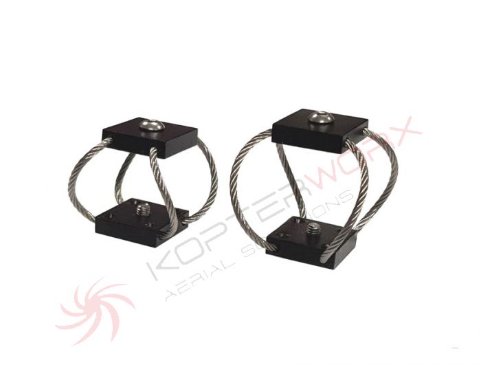
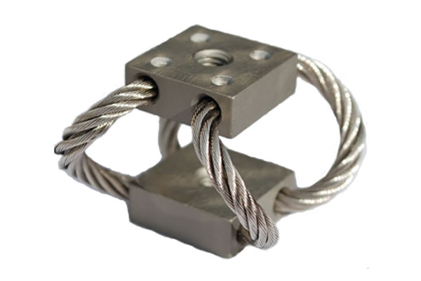
The compact wire rope isolator is smaller than a traditional wire rope and can absorb shock and vibration in small spaces. Single point mounting offers flexibility for integration into existing products.
Both compact wire rope isolators and wire rope isolators can be used on galley components where motors and fans produce vibrations onto surrounding structures. They can also be used to control vibration and thermal expansion.
VMC Group offers a variety of wire rope isolators that resolve shock and vibration issues in virtually any application. By selecting wire rope with the proper characteristics - wire diameter, number of strands, cable length, cable twist or lay, and the number of cables per section, we have created isolators that provide superior equipment protection. Ideally, passive isolation systems require no maintenance, use little space and keep functioning under varying temperatures and in corrosive environments.
As an elastic element, wire rope isolators will afford attenuation of vibration disturbances in much the same manner as they attenuate shock inputs. Wire rope isolators provide inherent damping by virtue of relative motion between wire strands. This damping limits vibration response peaks and limits responses to start-up and shut-down transients.
Isolators must also attenuate shock with minimum dynamic travel. A design that buckles under heavy shock loads without bottoming or permanent deformation provides the large deflection needed to bring the impacts within acceptable limits. When shock load is applied, the isolators soften and deform. This displacement reduces the acceleration level, through the controlled buckling of the wire rope loops.
This wire rope design handles both shock and vibration. In addition, three-plane, all-axes isolation permits installation in any attitude - vertically, horizontally or laterally.
An isolator’s primary purpose is to protect valuable equipment by reducing incoming vibrational wave energy. Because vibration and shock are everywhere, unprotected devices could be at risk of damage from a large number of potential sources, such as hazards during transport and handling, vibration generated by other equipment, or even seismic events. Wire rope isolators use premium metals to provide heavy-duty protection to this equipment with minimal maintenance requirements while offering a long product life.
A shock and vibration isolator acts as a buffer and stabilizer between an object and a vibration or shock source. When the surface on one side of an isolator receives a shock, the isolator re-distributes the shock into a lower amplitude and longer duration acceleration, reducing the stress experienced by supported equipment on the other side. In some applications, isolators use friction damping to absorb and dissipate energy in the form of heat.
Wire rope isolators are mainly used to isolate vibration and protect precise equipment. However, the issue of regulation of vibration isolators taking into account the nonlinearity of their characteristics was poorly understood in the modern literature. In this paper, the influence of structural parameters (diameter ratio and lay pitch of the single strand, and lay pitch and bending radius of the wire rope) on stiffness-damping characteristics of the Polycal WRI was investigated by the simplified finite element analysis method. The stiffness and damping prediction models including structural parameters and material properties were established. The results showed that the stiffness-damping characteristics were the best; when the diameter ratio of wire strand was 1.1, the inside layer wire pitch length was 6 times the diameter of the wire strand, the outside layer wire pitch length was 11 times the diameter of the wire strand, the pitch length of the wire rope was 7.5 times its diameter, and the bending radius was equal to 46.5 mm. The errors of the prediction for prestiffness and softened stiffness were within 5%, and the errors of prediction for the energy dissipation coefficient were within 10%.
Vibration is common in our lives. Especially in many industries, vibration is caused by the equipments operation, fluid flushing in pipes, and aero engine. This is harmful for operation safety [1–3]. Many vibration reduction and vibration suppression methods have been studied. Vibration isolators are widely applicable to production and living. Particularly, it is widely used in equipments with high load and vibration reduction requirements. In recent years, new type of vibration isolators and design of vibration isolation systems are hot topic for scholars. Wire rope isolator (WRI) has excellent rigidity damping characteristics, especially with high bearing capacity. It is widely used in mechanical manufacturing and construction. Therefore, it is necessary and significant to study the characteristics of the WRI with different structural parameters.
The characteristics of the WRI are studied through the experimental and theoretical methods [4–11]. Chen et al. [12] investigated the contact statues of a steel wire rope from the perspective of theoretical analysis. The result shows that the effect of the lay angle on the stiffness of the wire rope is different under different loads. Tinker and Cutchins [13] obtained the data of stiffness and damping characteristics of the WRI through dynamic experiment. It is also found that the damping of the WRI is related to coulomb-type friction. Demetriades et al. [14] studied the response characteristics under different loads for different structures of the WRI. The result indicated that the WRI exhibits the same characteristics under shear and roll loads. Wang et al. [15] experimentally investigated the effects of load frequency, amplitude and structural parameters on the dynamic characteristics of O-type WRIs. He found that the loading amplitude and geometric parameters of the isolator directly affects the dynamic characteristics of the isolator, while the loading frequency has no effect on it. Gerges [9] investigated the tension-compression mode of the wire rope spring. He presented a semianalytical model for a wire rope vibration isolator through experiment. Rashidi and Ziaei-Rad [7] investigated the quasi-static and dynamic characteristics of the WRI. It is suggested that there is not obviously relationship between hysteresis loops and loading velocity under quasi-static load. The dynamic results indicated that by increasing the frequency of excitation, the area of the hysteresis loop starts decreasing. Finally, a hysteresis analytical prediction model with high coincidence degree was established.
The finite element analysis method can reduce the cost of the experiment, and thus has been widely used in studying the characteristics of the WRI and wire ropes. Jiang et al. [16] found effective simplified finite element analysis method of analyzing the contact statues of wire ropes. It was found that the local contact deformation affects the accuracy of the results. Wang et al. [17] investigated the mechanical behavior of the YS9-8 × 19 braided wire rope under tensile load. By comparing the results of finite element analysis and experiment, the error between them was small, and the accuracy of the model was verified. By the finite element method, Xiang et al. [18] obtained the elastic-plastic contact stresses under axial and torsion loads of wire ropes, and investigated the elastic-plastic behavior of it. The finite element analysis results have a good agreement with the experimental test results, and a new prediction model was proposed. Yu et al. [19] applied the beam finite element method to analyzing axial tensile properties of the 91-wire strand. By comparing with the experiment results, the beam FEM could be used to predict the tensile properties of the steel wire rope. Song et al. [20] analyzed distributions of stress and deformation in the braided wire rope subjected to torsional loading. He found that the wires in the strands have the tendency to be screwed tightly and are in a stretched state when the lay direction of the strand coincides with its torsion direction. Cao and Wu [21] established the finite element model of wire ropes with different structural parameters and analyzed the stress distribution and deformation under cantilever beam state. The accuracy of the results of finite element analysis was slightly lower than the theoretical calculation results. Du et al. [22] presented a simulation of the 6 × 36 + WS RHRL wire rope. It is found that the stress of the wire rope was uneven, and the maximum stress occurs at the side of the wire. Yong et al. [23] conducted a finite element analysis of the IWRC636WS wire rope, and the elastic behavior of the wire rope under tensile loads was simulated. It is reported that nonlinear relationship between the axial tension and the axial elongation of the wire rope. Cen et al. [24] found effective simplified finite element analysis method by combining finite element method with experimental test. This method can be used to analyze the characteristics of the Polycal WRI. The above studies have studied the characteristics of wire ropes and vibration isolators by experiments and finite element methods and obtained some results. Considering the complexity of the wire rope isolator structure, there is less research on the relationship between the structural parameters of the WRI and the stiffness and damping characteristics of the WRI. Therefore, it is necessary to study the relationship between them, and provide guidance for practical engineering applications.
In this paper, the stiffness and damping characteristics of WRIs with different structural parameters were investigated. These structural parameters were number of wire ropes, material of wire, rope diameter (D), rope lay pitch (), single wire rope diameter (d), single wire strand lay pitch (), and wire rope diameter ratio (nr). A stiffness-damping prediction model consists of structural parameters of the Polycal WRI were established, which aims to provide powerful help for the structural design and wire rope selection of the Polycal WRI.
The energy dissipation coefficient is a key parameter evaluating the effective vibration isolation property of a WRI. It is an important reference for evaluating the damping characteristics of the WRI. Because of sliding friction between the wire strands and the internal friction of wires, the isolators exhibit nonlinear hysteretic behavior. Typical load-displacement curve of the WRI is shown in Figure 1. The damping characteristics of the WRI are related with the area which is enclosed by the loading and unloading curve of the WRI under compression. The energy dissipation coefficient C was calculated as follows:where Aloop was the area of the hysteresis loop (N·mm), Fmax and Fmin were the maximum and minimum loads (N), respectively, of the WRI in the compression loading-unloading process. Xmax and Xmin were the maximum and minimum displacement (mm) in the loading-unloading process.
In most of the wire rope isolators, during the load-bearing process, the upper and lower pallets are mainly supported by the curved steel wire rope, and the bending stiffness and deformation process of the steel wire rope play a decisive role. Therefore, this paper mainly uses the stiffness and energy dissipation coefficient as indicators to measure the effectiveness of the wire rope isolators.
As shown in Figure 2(a), the WRI was composed of two pallets and twelve 6 × 19 IWS wire ropes. In this paper, the simplified finite element method is used to obtain the WRI load-displacement hysteresis loop, and the WRI stiffness damping of different structural parameters is discussed. We have referenced the simplified finite element method which was established by Cen et al. [24]. This method mainly simplified the single strand into a single wire. The 6 × 19 IWS wire rope was simplified into the 1 × 7 wire rope, as presented in Figure 2(b). Based on the simplified method, this paper studies the stiffness and damping characteristics of the isolators with different structural parameters and establishes the prediction model of the stiffness damping of the wire rope isolator with structural parameters as variables.
This paper is mainly based on the GGQ-99 Polycal WRI. By changing structural parameters, the diameter ratio and lay pitch of the single strand and lay pitch and bending radius of the wire rope, different finite element models were set.
In this presented model, the data source of the simulation of the WRIs refers to papers of Cen et al. [24], Jiang et al. [25], and Erdonmez and Imrak [26]. The material properties of the center and side wires are defined by the bilinear elastic-plastic kinematic hardening model in the ABAQUS material library, as shown in Table 1. By compression of corresponding strands, the max equivalent compression stress of the strand and equivalent compression elastic modulus are equal to and Ep, respectively. Ee is equal to the equivalent tension elastic modulus which is measured by the tension of the strands. The density is ρ = 7850 kg·m−3, and the Poisson’s ratio is μ = 0.3 [24].
The stiffness of the WRI determines the load-bearing capacity of the vibration isolation system, regardless of whether the WRI is subjected to a static load or a strong impact load. The softening load of the WRI and the subsequent softening stiffness both affect the efficiency of vibration isolation and stability of the entire isolator system. The damping characteristic reflects the ability to absorb shock vibration energy of the isolator in the vibration isolation system. There are many factors that affect the static stiffness and damping characteristics of the WRI, including the selection of the wire rope, number of wire ropes, material of steel wire, wire rope diameter (D), rope lay pitch (), single wire rope diameter (d), single wire strand lay pitch (), wire rope diameter ratio (nr), and arc wire rope bending radius (R).
As shown in Figure 3, the diameter ratio (nr) of the 1 + 6 + 12 center strand or the lay strand is defined as follows:where rc and rs are the diameters of the center wire and lay wire in the single strand, respectively.
Figure 3 shows the 1 + 6 + 12 single-strand wire rope. It was stipulated that the 1 + 6 + 12 single-strand wire rope has the same other structural parameters; the first layer wire pitch length was 6 times the diameter of the single wire rope, and the second layer wire pitch length was 11 times the diameter of the single wire rope. The diameter of the wire rope was 8 mm in the study of the GGQ-99 Polycal WRI. The diameter of the center strand was 2.839 mm, and the diameter of the lay strand was 2.581 mm. Obviously, the former was 1.1 times more than the latter. The lay pitch length was 60 mm (7.5 times diameter of the wire rope), and the bending radius was 46.5 mm of the arc wire rope. The diameters of the center wire and lay wire in different strands with different diameter ratios of the GGQ-99 are listed in Table 2.
According to the simplified FEM model, the tensile and compression of the single strand with different diameter ratios were calculated. The elastic tensile and compression modulus and compression ultimate load of the single strand were obtained. These mechanical parameters were used to calculate the stiffness-damping characteristics of the WRI. It is presented in Table 3. It could be seen that the elastic tensile modulus significantly reduced with increased diameter ratio. But the elastic compression modulus increased with increased diameter ratio. The compression ultimate load is kept steady basically with increased diameter ratio. The reason is that the compression ultimate load indicated the friction properties between the center wire and lay wire. The friction between the center wire and lay wire was retained about the same during calculating the model with different diameter ratios. So, the compression ultimate loads showed little changes.
According to the simplified FEM model, the compression loading-unloading processes of the GGQ-99 WRI with different diameter ratios were simulated. Different load-displacement hysteresis loop curves of the WRI are shown in Figure 4. The ratio between the prestiffness K1 and softened stage stiffness K2 indicated the impact resistance for the WRI. The smaller this value, the better the impact resistance. The energy dissipation coefficient was used to evaluate the damping characteristic. The higher this value, the better the damping characteristic. The results are shown in Figure 5.
As shown in Figure 4, the compression load of the WRI increased with increasing of the diameter ratio of the wire strand. This result is related to the elastic compression modulus of the single strand. As shown in Figure 5, the ratio of K1 to K2 was increased with increasing of the diameter ratio of the wire strand. The ratio of K1 to K2 reached the minimum when the diameter ratio was equaled to 1.1. It means that the GGQ-99 WRI was easier to maintain the stability of the vibration isolation system through large deformation. The energy dissipation coefficient for the WRI decreased with increasing of the diameter ratio of the wire strand. When the ratio of the strand was equaled to 1.1, the energy dissipation coefficient reached maximum. These results indicate that the Polycal WRI has better damping characteristics, which could effectively consume the impact load and eliminate the vibration from the isolation system.
Based on the diameter ratio of the wire strand to 1.1, the main purpose of this section is to study the effect of the outer layer side wire pitch length () on the stiffness-damping of the Polycal WRI. During the process of creating the simulation model, the first layer side wire of the strand steel wire rope () was unchanged and equal to 6 times the diameter of the wire strand. The was 7 times, 8 times, 9 times, 10 times, and 11 times the diameter of the wire strand. The relation between the pitch length and diameter of the wire strand (d) is expressed in equation (3). The geometric dimensions of the single wire strands with different pitch lengths are shown in Table 4.
As shown in Table 5, the equipment tensile modulus, compression modulus, and softened stress of the wire strands with different were obtained by axial tension and compression. The modulus of the tension was continuously increased with increasing of the outer layer side wire pitch. The modulus of the compression had a small variation with increasing of the outer layer side wire pitch basically, and the maximum load of the corresponding compression process decreased.
The equipment tensile and compression performance of wire strands with different were used to define the bilinear elastic-plastic kinematic hardening material properties of the center and lay strand assembled in the GGQ-99 WRI. As shown in Figure 6, the load-displacement hysteresis loops of different lay pitches had a small variation. Besides, the modulus of the compression was not changing with increasing of the outer layer side wire pitch. Combined stiffness-damping characteristics of the GGQ-99 WRI with the different wire strand pout are shown in Figure 7. When the was 11 times the diameter of the wire strand, the ratio of K1 to K2 reached the minimum. At the same time, the Polycal WRI had large prestiffness and the most obvious softening characteristics, not only could withstand large loads but also could easily maintain the stability of the vibration isolation system through large deformation under the action of large loads. The energy dissipation coefficient of the WRI remained basically unchanged, when the ratio of the outside lay pitch and the diameter of the strand increased.
In the process of compression loading-unloading of the Polycal WRI, not only the slippage of the wires exists in the strand but also the overall slippage of the strands in the rope. Therefore, the influence rule of the pitch length on the wire rope is discussed in this section. The diameter ratio, the inside layer wire pitch length and outside layer wire pitch, was equaled to 1.1. It was 6 times the diameter of the wire strand and 11 times the diameter of the wire strand, respectively. The relation between the pitch length and diameter of the wire rope (D) is expressed in equation (4). Table 5 lists the geometric dimensions of the single wire strands with different pitch lengths. The load-displacement hysteresis loops of the GGQ-99 WRI with different pitch lengths are shown in Figure 8.
As shown in Figure 8, the compression load of the WRI increased with increasing of the pitch length of the wire rope. The increase of the pitch length contributed to the increase of the angle between the center strand and lay strand. The bearing axial load of the lay strand increased with angle between center strand and lay strand decreasing. So, the compression load of the WRI was increased with the increasing of the pitch length of the wire rope.
The stiffness-damping characteristics of the GGQ-99 WRI with different pitch lengths of wire ropes are shown in Figure 9. As shown in Figure 9, both the ratio of K1 to K2 and the energy dissipation coefficient of the WRI fluctuated with the increase of the pitch length of the arc rope. When the rope pitch was equaled to 7.5 times the diameter of rope, the ratio of K1 to K2 was the smallest and less than 0.2 and the energy dissipation coefficient was the biggest.
The characteristics of the Polycal WRI depend on the structure of the wire rope, including the diameter of the single strand, the pitch length of the single strand, and the bending radius of the wire rope. In this section, the influence of the bending radius (R) of the arc rope on the stiffness-damping characteristics of the Polycal WRI is studied. The diameter ratio of the wire strand was 1.1. The inside layer wire pitch length was 6 times the diameter of the wire strand. The outside layer wire pitch length was 11 times the diameter of the wire strand, and the pitch length of the wire rope was 7.5 times its diameter. The bending radius was equal to 46.5 mm, and the bending radius of the wire rope was 50 mm, 55 mm, 60 mm, and 65 mm, respectively. The FEM models of the GGQ-99 WRI with different bending radii are shown in Figure 10. The load-displacement hysteresis loops of the GGQ-99 WRI with different bending radii of arc ropes are shown in Figure 11.
As shown in Figure 11, the compression load of the WRI increased with increasing bending radius of arc ropes. Because the compression load of the WRI was inversely proportional to the curvature of the wire rope, the curvature of the wire rope decreased with increasing bending radius of arc ropes. The compression load of the WRI increased with increasing bending radius of arc ropes.
The stiffness-damping characteristics of the GGQ-99 WRI with different bending radii of the wire rope are shown in Figure 12. The ratio of K1 to K2 increased with increasing bending radius. However, the energy dissipation coefficient of the WRI decreased with increasing bending. When the bending radius was equal to 46.5 mm, the ratio of K1 to K2 was the smallest and the energy dissipation coefficient was the biggest.
In conclusion, the stiffness-damping characteristics were the best; when the diameter ratio of the wire strand was 1.1, the inside layer wire pitch length was 6 times the diameter of the wire strand, the outside layer wire pitch length was 11 times the diameter of the wire strand, and the pitch length of the wire rope was 7.5 times its diameter. The bending radius was equal to 46.5 mm.
In the previous section, the influence rules of the diameter ratio of the wire strand (nr), the pitch length of the wire strand (), the pitch length of the wire rope (P), and the bending radius (R) for the stiffness-damping performance of the Polycal WRI were discussed. The prediction model of the stiffness-damping characteristic of the WRI was established by using the dimensionless diameter ratio of the wire strand (nr), the pitch length of the wire strand (), the pitch length of the wire rope (P), and the bending radius (R). The theoretical basis of equations (5) and (6) is the theorem in dimensional analysis. According to the principle of dimensional analysis, all structural parameters are transformed into a dimensionless form, and the number of variables is reduced to obtain the corresponding calculation formula as follows:where E1 is the elastic modulus of the steel wire material (E1 = 193000 MPa), H is the height of the GGQ-99 WRI (H = 99 mm), and D is the diameter of the arc rope (D = 8 mm). The x, k, and c are the undetermined coefficients in the stiffness and damping models, respectively.
As shown in Table 8, the errors of the prestiffness and softened stiffness fitting formulas of the WRI were all within 10%, and more than half of the errors were within 5%. The error of the energy dissipation coefficient of the WRI with the formula was basically within 20%, and more than half of the errors were within 10%. It could be considered that the formula fitted in this study is accurate and reliable by analysing the error results of the overall data. In the design of the Polycal WRI, the stiffness-damping characteristics could be quickly obtained.
The wire rope structural parameters of the GGQ25-62 Polycal WRI are given in Table 9. Besides, the values of H, D, and R are 62 mm, 4.68 mm, and 27.15 mm, respectively.
Through the out-of-plane compression loading-unloading experiment of the WRI, its stiffness-damping characteristics were obtained. Figure 13 shows the load-displacement curve of the GGQ25-62WRI, and the values of K1, K2, and C could be calculated from this figure, and Table 10 also shows the specific values.
This paper firstly presented the results of the mechanical properties of the wire rope with different diameter ratios and lay pitches of the single strand. By using the corrected simplified finite element method of the Polycal WRI, the influence of the diameter ratio and lay pitch of the single strand and the lay pitch and bending radius of the wire rope on the stiffness and damping characteristics of the Polycal WRI were studied. Several key conclusions are summarized as follows:(1)The stiffness-damping characteristics were best; when the diameter ratio of wire strand was 1.1, the inside layer wire pitch length was 6 times the diameter of the wire strand, the outside layer wire pitch length was 11 times the diameter of the wire strand, the pitch length of the wire rope was 7.5 times its diameter, and the bending radius was equal to 46.5 mm.(2)The effective prediction models of stiffness and damping about the structural parameters of the wire rope were established, which combined the properties of a steel wire material and the overall structure of the WRI. More than half of the errors of the prestiffness and softened stiffness fitting formulas of the Polycal WRI were within 5%. And more than half of the errors of the energy dissipation coefficient of the WRI were within 10%. The fitted value was compared with the experimental data, the errors were within 20%, and the prediction model was verified.

Enidine Defense designs and manufactures suspension systems and vibration isolation systems for the military and defense sectors. Our Defense products are specifically designed for military applications including HERM (High Energy Rope Mount) mounts for cabinet isolation, SIDAS (Shock Isolator Double Acting Spring), DAMSI (Double Acting Mechanical Shock Isolator) and wire rope isolators for commercial-off-the-shelf (COTS) electronics. Additional divisions also offer a variety of motion control products, such as Aerospace Controls, which offers solutions for today"s most demanding Aviation and Defense Applications.
Enidine developed large displacement SKID isolators to protect next generation missile systems. A special elastomer was developed (Enitemp IV) to provide excellent shock isolation under a wide range of environmental conditions. ITT Enidine Inc."s skid isola...
Enidine Inc. developed the HERM (High Energy Rope Mount) Isolator for NAVY cabinet isolation and rafted deck systems. They have successfully passed barge testing and reduced shock inputs to levels compatible with COTS equipment.
To isolate heavy loads against shipboard shock inputs, ITT Enidine Inc. developed the Double Acting Mechanical Shock Isolator (DAMSI). The DAMSI is a purely mechanical shock isolator featuring our patented friction spring damping element. A single DAMSI rep...
Small Vibration Mount offers Big Performance Use Enidine Compact Wire Rope Isolators for the best performance in vibration isolation and small vibration mount configurations. The compact design is smaller than most wire ropes and can provide both shock an...

Wire-rope isolator selection is a three-step process. First the designer defines the system into which the isolator is going — by supported load, number of isolators to support the load, and whether the application will see just compression or rolling. Then the engineer defines the excitation and natural system frequencies and calculates maximum isolator stiffness.
Vibrations damage machines and electronics, so designs often incorporate wire-rope isolators, air springs, or elastomers — but elastomers only attenuate noise and vibration levels. Wire rope isolators do this and attenuate shock too.
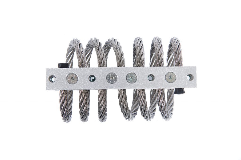
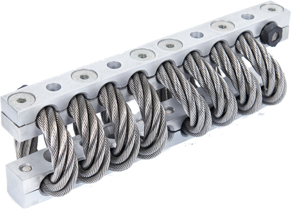
Standard wire-rope isolators from some manufacturers are made of stranded stainless-steel cable that threads through aluminum-alloy retaining bars. In some cases, the split bars clamp onto the cables. Corrosion-resistant metal construction gives the isolators a design unaffected by temperature extremes, ozone, chemicals, oils, and abrasives.
It’s expensive to keep equipment perfectly balanced, and it’s inefficient to add braces. But adding wire-rope isolators is cost effective — and done upfront, it protects machine welds and brackets from fatigue.
Part of some helical isolator designs is a patented crimp pattern. An array of mounting options and sizes exist with versions to meet commercial, industrial, and defense including MIL standards. The samples reviewed in the above video include both traditional bar and compact isolators — these square ones. One benefit to the compact versions is that they install with just a single point of attachment at each interface.
Options are through-hole, countersunk, and threaded bars for mounting. Its wire-rope isolators come in two-loop versions all the way to full loop numbers. Another option for high-fatigue applications is a “bellmouth” having mount bars with radii manufactured into the wire-rope hole edges. However, note that wire-rope isolators exhibit non-linear stiffness so small deflections (usually associated with vibration isolation) induce different spring rates than large shock deflections. Published values average vibration stiffness and shock-stiffness values for use in equations to predict system performance. Just remember that stiffness values are for full-loop versions — and reduced-loop versions have stiffnesses that are the unit’s standard stiffness times the ratio of actual loops to the standard number of full loops.

New Elesa ranges of stainless steel damping elements offer different designs for different jobs – AVC wire rope isolators are suitable for low-frequency damping with high deflections. Their function is to prevent damage to structures and preserve the correct operation of sensitive equipment while also reducing noise. The sister range of AVM spring mounts is excellent for low vibration with high deflections, while AVF metal cushions are compact for small spaces, higher frequencies and smaller deflections. Overall, these high-performance vibration dampers are used in compliance with safety regulations on vibration and noise (DL 81/2008). Stainless steel is chosen for many applications because it performs over a long lifespan with low-to-zero maintenance, and is unaffected by ageing as generally found in rubber isolators.
Elesa wire rope isolators are very high-performance shock absorber and vibration dampers that can be used in endless applications. Typically from oil exploration, radio equipment and generator sets, to blowers/fans, and other HVAC style installations. They are very useful because they maintain excellent isolation performance under maximum shock in severe environmental conditions, for example chemical pollution or extreme temperatures. Stainless steel wire rope isolators have a long service life and can adapt to elastic displacement in all dimensions This allows multi-directional isolation, with installation in many different orientations, making them suitable for railway compressors, aviation and marine engineering as well as camera mounts on UAVs and robotic camera platforms.
AVM spring mounts offer low-frequency damping at higher deflection rates, combined with the higher frequency damping of rubber end pads. They suit acoustic and motor mountings where a wider range of vibrations and larger deflections are likely also where wind loads or asymmetric movement patterns are experienced, such as in engine starting.
At the other end of the scale, AVF metal cushions provide a very compact solution to the needs of machine tool manufacturers. They are ideal for machine component mounting where space is at a premium but deflection is minimised – such as in electronics equipment or isolation of exhaust systems. These wire mesh vibration dampers can be used for pass-through mounting or with an inset machine screw for component retention.
The reasonable conclusion from the previous results referring to the effect of directional arrangement of isolator systems was to investigate how on compression stiffness of wire rope isolator systems influences lateral shear accompanying to free compression. Lateral shear and rolling phenomena appearing during free compression of wire rope isolators were further analyzed experimentally. In source literature where wire rope isolator compression tests have been broad described, the shear phenomenon influence is often omitted due to the testing stand construction that features one-directional loading pass as in strength testing machines. Contrary to test conditions described in many studies, in this paper are assumed conditions of free compression, which referred rather to investigate of combined stress states.
The aim of further investigations was to determine static and dynamic characteristics of two configuration, namely “parallel” and “serial”, each consisting of two isolators. It was assumed that Y axis of coordinates is parallel to the isolators of the central axes, and Z axis is perpendicular to the surfaces of the upper and the lower plates as shown in Figure 8.
Figure 9 presents changes of the upper plate lateral displacements (along Y axis) perpendicular to the vertical loading direction Z during cyclic down and up 5 kg load tests carried out on “parallel” configuration of two wire rope isolators. Similar characteristics were obtained for the second lateral direction X, but the range of displacement changes was less than those for Y direction. It was additionally noticed that vertical, symmetry axis of the upper plate was subjected to a small angle deviation what can cause instability of the whole system in extreme case. Dangerous of loss of stability is greater for “serial” than for “parallel” configuration.
Figure 10 shows a comparison of displacements in vertical Z direction for two different configurations. The upper plate of the stand was loaded by masses in the following order: 5.88, 2.27, 1.35, 1, 0.94, 0.76, 0.74, and 0.49 kg. It can be noticed that at “serial” configuration, a set of isolators increasing the vertical displacement is higher than those at “parallel” configuration. In addition, in case of “serial” configuration, after adding the mass of 0.94 kg, the loss of stability occurred.
Only “parallel” configuration of two isolators was further considered. There were determined hysteresis loops to identify average static stiffness characteristics similarly as before for “star” and “triangle” configurations but previously consisting of three isolators. The main reason for authors was looking for an answer for a question if it would be correct to apply additivity theorem to static stiffness measured in vertical direction despite identified lateral deflection influences. An exemplary hysteresis loop obtained in quasi-static successive uploading and unloading process carried out on “parallel” configuration of two isolators is presented in Figure 11. The identified average static stiffness characteristic was evaluated using LSQ method.
In engineering practice, it is required to compare static stiffness characteristics made for different configurations and different numbers of isolators in the same chart, considering the number of supporting isolators under the assumption that additivity property is acceptable. It was done here, and the result shown in Figure 12 is a sort of proof that such assumption was correct in case of using wire rope isolators.

VMC Group offers a variety of wire rope isolators that resolve shock and vibration issues in virtually any application. By selecting wire rope with the proper characteristics - wire diameter, number of strands, cable length, cable twist or lay, and the number of cables per section, we have created isolators that provide superior equipment protection. Ideally, passive isolation systems require no maintenance, use little space and keep functioning under varying temperatures and in corrosive environments.
As an elastic element, wire rope isolators will afford attenuation of vibration disturbances in much the same manner as they attenuate shock inputs. Wire rope isolators provide inherent damping by virtue of relative motion between wire strands. This damping limits vibration response peaks and limits responses to start-up and shut-down transients.
Isolators must also attenuate shock with minimum dynamic travel. A design that buckles under heavy shock loads without bottoming or permanent deformation provides the large deflection needed to bring the impacts within acceptable limits. When shock load is applied, the isolators soften and deform. This displacement reduces the acceleration level, through the controlled buckling of the wire rope loops.
This wire rope design handles both shock and vibration. In addition, three-plane, all-axes isolation permits installation in any attitude - vertically, horizontally or laterally. These design features make very compact mounting systems possible for use in shipping/transport containers.

By their nature, wire rope isolators are self-snubbing, fail-safe, and captive to the ultimate limits of the metals. They are insensitive to temperature from cryogenic up to near anneal. They resist most industrial and natural environments. The VMC Group’s manufacturing process is set up to create special winding configurations to customize spring rate and deflection.
The tables referenced are not a substitute for proper analysis of system requirements. The key elements to performing a meaningful selection and analysis are:Payload weight, geometry, center of gravity, isolator location
Quite often, we size the isolation system to do the best job within reasonable size constraints. Any theoretical isolator selection must be reconsidered in light of real-world limitations on equipment sway space and the isolator’s physical size and stability. Some very simple equations are used in selecting wire rope isolators. When considering shock, we use an energy method. We reduce a shock pulse to an equivalent velocity step. For a few typical shock inputs, the velocity steps are as follows:
With the spring rate (K) and dynamic displacement (Dd) established, we can now select an isolator. However, designers should take caution: The spring rates published are average. The placement of the static load on the load-deflection curve modifies the spring rate, available dynamic deflection capability, and cross-axes stability. The load-deflection curves for the principal and cross axes should be requested and considered when making any selection. VMC Group’s modeling software takes both the full third-order curve and damping into account.
Particularly with wire rope isolators, a robust system should be designed such that variances in the effective natural frequency due to dynamic damping do not significantly alter performance in the desired band.
VMC Group pioneered the wire rope isolator more than fifty years ago. Steel wire rope is strong, flexible, and fatigue-resistant because it is made up of many individual strands of high-tensile strength drawn wire. When bent or buckled, it is as much an elastic element as any tempered coil spring or elastomeric mount. Due to frictional forces between the individual strands, wire rope can provide a significant level of dynamic damping — typically 15% to 20% of critical damping. This level of damping makes wire rope isolators attractive for applications that involve sweeps through resonance and transients such as shock.
To create a shock and vibration isolator from wire rope, VMC Group creates buckling elements either in the form of helical loops (Helical Series isolators), or individual arcs (Arch and Circular Arch Series). Like any buckling element, a third-order force-deflection curve results. This can also be called a “softening curve.” Graphically, the curve starts from zero and is nearly linear. As load and deflection increase, the curve eventually begins to flatten. At some further point along the load-deflection curve, it becomes steeper, creating an inherent snubbing effect.
Shock is attenuated by spreading the input energy over time and distance. The flattened section of the curve is excellent for this. The load-deflection curve of a wire rope is very long given the isolator’s physical size. The isolator is a hollow, slender device capable of collapsing in on itself. For its size, it can deflect far more than elastomer and more than a coil spring. This is not to say that wire rope isolators are strictly shock attenuators and not vibration isolators. As an elastic element in a spring-mass system, it will exhibit a natural frequency and thereby form a low-pass filter for vibration energy in the same manner as any coil spring or elastomeric isolator. VMC Group does not list load ratings for individual wire rope isolators and we publish two different average spring rates. We have average static load-deflection curves available in both hard copy and electronic form for the principal isolator directions. They are always available on request. We have also chosen not to include load-deflection curves for wire rope isolators and encourage you to obtain assistance from VMC Group’s Engineering Services Division at 1-800- 569-8423. In almost all cases, application assistance, including analysis and modeling, is performed free of charge and without obligation to the customer.
To determine how much load can be placed on a wire rope isolator, we must first ask what the customer intends to do with the isolator. If small amplitude vibration is the input, we can place the static load along much of the lower two- thirds of a typical load-deflection curve. The effective static spring rate is the tangent of the curve at that load point. If large amplitudes, particularly deep shocks, are to be the input, we place the static load down in the linear first third of the curve. This allows the load to ride high up onto the curve in response to the shock. In this case, the effective average spring rate is a global straight-line, end-to-end slope of the curve over the excursion. To provide average values in the catalog for design purposes, we take the vibration spring rate as the tangent slope near zero and the shock spring rate as the overall end-to-end straight-line slope over the curve. VMC Group’s modeling software takes the entire third-order curve into account. The non-linear nature of the response curve and the presence of input-dependent damping are good reasons to work with our engineering department when selecting an isolator.
Another reason to consult with VMC Group before selecting your wire rope isolators is the interrelationship between the axes of the isolator. Wire rope isolators are elastic elements in all directions simultaneously. This makes them suited for all-attitude and mobile applications and applications that involve complex, off-axis inputs. The physics of the isolator is such that most inputs produce a response with components in more than one direction.
We can manage this characteristic using properly engineered solutions that take all axes into account. It should be noted that use of the tension direction for primary shock attenuation is not recommended. This is due to the predominance of tensile loading within the cable that results in a stiffening curve.
As the world leader in wire rope technology, our custom plate assemblies, and custom-designed isolators have been used in various applications for over 50 years. Whether for avionics and aerospace equipment, electronics apparatus, engine gensets, auxiliary power supplies, or other sensitive equipment requiring isolation, our engineering group will work with you throughout the entire design process to provide the custom solution you require. Our modeling software has an excellent reputation in the industry for its accuracy and will ensure your project is designed correctly from the beginning. Our plate assemblies and custom isolators have been designed to support weights from just a few pounds to over 100,000 pounds and take the form of special length bars, differing diameter wire, and winds, custom rail systems, plate assemblies, trays, and skids. Our helical wire rope isolators have been qualified on numerous military projects requiring the following typical specifications for shock and vibration:

M. Leblouba, S. Altoubat, M. E. Rahman and B. P. Selvaraj, Elliptical leaf spring shock and vibration mounts with enhanced damping and energy dissipation capabilities using lead spring, Shock and Vibration, 2015 (2015).
G. F. Demetriades, M. C. Constantinou and A. M. Reinhorn, Study of wire rope systems for seismic protection of equipment in buildings, Engineering Structures, 15 (1993) 321–334.
P. S. Balaji, L. Moussa, M. E. Rahman and L. Vuia, Experimental investigation on the hysteresis behavior of the wire rope isolators, Journal of Mechanical Science and Technology, 29 (2015) 1527–1536.
Z. H. Zhu and S. A. Meguid, Nonlinear FE-based investigation of flexural damping of slacking wire cables, International Journal of Solids and Structures, 44 (2007) 5122–5132.
Y. Prawoto and R. B. Mazlan, Wire ropes: Computational, mechanical, and metallurgical properties under tension loading, Computational Materials Science, 56 (2012) 174–178.
X. Li, S. Wang and J. Zhou, Analysis of elliptical Hertz contact of steel wires of stranded-wire helical spring, Journal of Mechanical Science and Technology, 28 (2014) 2797–2806.
W. G. Jiang, M. S. Yao and J. M. Walton, A concise finite element model for simple straight wire rope strand, International Journal of Mechanical Sciences, 41 (1999) 143–161.
E. Stanova, G. Fedorko, M. Fabian and S. Kmet, Computer modelling of wire strands and ropes Part I: Theory and computer implementation, Advances in Engineering Software, 42 (6) (2011) 305–315.
E. Stanova, G. Fedorko, M. Fabian and S. Kmet, Computer modelling of wire strands and ropes part II: Finite element-based applications, Advances in Engineering Software, 42 (6) (2011) 322–331.
ASTM A931-08 (2013) Standard test method for tension testing of wire ropes and strand, ASTM International, West Conshohocken, PA, www.astm.org (2013).


 8613371530291